Prevention of Water Intake Blockage by Ice during Supercooling Events
This article has a reply.
VIEW THE REPLYThis article has a reply.
VIEW THE REPLYPublication: Journal of Cold Regions Engineering
Volume 37, Issue 1
Abstract
Blockage of water intakes by underwater ice formation during supercooling events is a widespread and common problem in northern regions during winter. In this context, underwater ice formation means deposition of frazil ice and growth of platelet ice. Blockage happens when underwater ice forms on the structural components of the intakes, particularly the intake trash racks, decreasing the area of the intake available for flow. This article evaluates potential solutions for preventing blockage. The solutions are collected into four broad categories: avoidance, prevention, mitigation, and remediation. Avoidance locates the intake so that it is never exposed to supercooled water. Avoidance is not possible in rivers and streams and requires depths in lakes and reservoirs that are not reachable for most intakes. Prevention stops supercooled water from entering the intake. The use of heat to warm the intake flow so that it is not supercooled is the most reliable way of preventing intake blockage by underwater ice. The formation of stable ice covers is a reliable means of preventing blockage events but cannot entirely eliminate them. Mitigation modifies the intake, or its operation, to prevent blockage. Ice adhesion to trash rack bars can be reliably prevented by maintaining the bar surface at a temperature greater than 0°C. Other approaches to mitigation including reducing intake flow, modifying the trash rack design, using coatings or alternative materials, or insulating portions of trash rack bars are not reliable for preventing blockage. Remediation actively removes underwater ice from the intake components while the intake is in operation. Mechanical or manual raking of the intake trash racks to remove deposited frazil ice can be a reliable means of preventing blockage. In addition, a strategy, management, addresses intake operation when practical measures for blockage prevention are not available. Management accommodates periodic blockages into the operation of facilities through detection, damage prevention, and quick and efficient restarts.
Introduction
Blockage of water intakes by underwater ice formation during supercooling events is a widespread and common problem in northern regions during winter. In this context, underwater ice formation means deposition of frazil ice and growth of platelet ice. Blockage happens when underwater ice forms on the structural components of the intakes, particularly the intake trash racks, decreasing the area of the intake available for flow. Typically, the underwater ice forms through deposition of frazil ice convected by the intake flow on the components of the intake. In some cases, the underwater ice forms through in situ growth of stationary platelet ice on the components. The decrease in the open flow area increases the energy losses of the intake flow, placing downstream facilities outside their normal operating conditions. An intake is considered blocked when downstream pumps, turbines, or processes are placed so far out of their normal operating conditions that a shutdown becomes necessary.
Ice blockages can happen to any facility requiring a water intake. These range from large water users, such as hydroelectric, nuclear power and fossil fuel power producers, industrial factories, and municipal water supplies, to small users, such as run-of-the-river hydroelectric plants and fish hatcheries. It has been recognized for quite some time that the operation of water intakes during supercooling events is challenging (Henshaw 1887; Barnes 1906; Murphy 1909), and there are a number of direct accounts of blockages (Baylis and Gerstein 1948; Foulds 1974; Foulds and Wigle 1977; Carey 1979; Parkinson 1987). Solutions for preventing blockages have tended to be developed on a case-by-case basis. This approach reflects the fact that blockages tend to be fought locally, at the plant level, with limited coordination of efforts to address the problem among or across different intake operator groups. Even so, many solutions for preventing blockage based on different approaches have been proposed over the years. In no cases have these solutions been rigorously evaluated for effectiveness. Testing is difficult for several reasons. Water intakes are often located a significant distance from the main facility and often underwater, making them difficult to observe. Blockage often occurs infrequently and sporadically, making any systematic observation program difficult to justify. Laboratory experiments have provided insights into frazil ice formation (Barrette 2021), but laboratory testing on real, full-scale structures is relatively expensive and not commonly done. In addition, it is difficult to generalize from experience in the field because of the wide variety of intake designs and the wide range of environmental conditions under which they operate.
Objectives and Scope
This article evaluates the proposed solutions for preventing underwater ice blockage during supercooling events in a broad context that can be applied to all water intakes. The evaluations are based on the authors’ experience with a range of intakes that have successfully (and not so successfully) coped with underwater ice formation, the recent literature, and the latest understanding of the causes of intake blockage by underwater ice. The article begins by providing background on supercooling events and the different mechanisms of underwater ice formation on the intake structure. The various solutions for preventing blockage are collected into four broad categories for evaluation. These categories are as follows:
1.
Avoidance locates the intake so that it is never exposed to supercooled water.
2.
Prevention stops supercooled water from entering the intake.
3.
Mitigation modifies the intake or its operation to prevent blockage.
4.
Remediation actively removes underwater ice from the intake components while the intake is in operation.
The article discusses the relative effectiveness of the above solutions in preventing intake blockage by underwater ice. Solutions that are effective in preventing blockage of water intakes by underwater ice formation during supercooling events are termed “reliable.” In addition to these categories, there is a strategy, management, which addresses intake operation when practical measures for blockage prevention (the first four categories) are not available. This strategy accommodates periodic blockages into the operation of facilities through detection, damage prevention, and quick and efficient restarts.
This article only addresses ice blockage of intakes that result from underwater ice formation during supercooling events. Intakes can be faced with other types of ice problems that do not occur during supercooling events such as blockage by slush ice and ice floes, ice impacts, and ice ride-up and pile-up events. These problems are beyond the scope of this article.
Background
Supercooling Events
Supercooling events are common in rivers and streams and occur in lakes and reservoirs. It is appropriate to refer to a supercooling event because each episode of supercooling has a distinct start time when the water temperature drops below 0°C, the ice/water equilibrium temperature, and a distinct end time when the water temperature rises back to 0°C.
The first requirement for a supercooling event to occur is turbulent water. Rivers and streams are continuously turbulent if their flow velocity exceeds modest levels. Lakes and reservoirs typically do not have currents but are intermittently turbulent depending on the presence of wind and ice conditions. Winds blowing across the open surface of lakes and reservoirs generate turbulence that creates a mixed upper layer with uniform temperatures. The second requirement is for a period of intense heat transfer from the water surface that cools the water temperature to below 0°C. This heat loss only occurs when the water surface is not covered by floating ice, and, as a result, supercooling events are strongly associated with open water. The heat transfer is driven by frigid air temperatures and various combinations of wind, low humidity, and clear skies. Generally, but not always, supercooling events happen at night when there is no solar radiation (insolation) to offset the heat transfer to the atmosphere.
Vertical mixing occurs relatively rapidly in turbulent waterbodies. In rivers and streams, supercooled water is mixed throughout the entire depth of the channel. In lakes and reservoirs, supercooled water is transported throughout the entire mixed layer, which can extend to the bed in nearshore areas. Detailed observations of supercooling events in rivers and streams are available (Richard and Morse 2008; Kalke et al. 2019; Ghobrial and Loewen 2021; Ghobrial et al. 2021). Detailed observations of supercooling events in lakes and reservoirs are not available, but reports of bottom ice conditions and intake blockage indicate that supercooling events do occur in these waterbodies (Kempema et al. 2001; Daly and Kempema 2010; Daly and Ettema 2006).
Seeding
The key point is that ice does not form spontaneously when the water temperature drops below 0°C. Water has an apparent thermodynamic barrier to the spontaneous creation (homogeneous or heterogeneous nucleation) of ice crystals at the low levels of supercooling that occur during a supercooling event (Dorsey 1948; Osterkamp 1977). For examples of typical supercooling temperatures, Kalke et al. (2019) observed water temperatures during 93 supercooling events in a northern river. They observed an average supercooling over all events of −0.024°C and a maximum supercooling of −0.106°C. As a result of this barrier, it is likely that the spontaneous creation of ice from liquid water never occurs during supercooling events in natural water bodies. Rather, seed crystals, introduced from outside the waterbodies, are required to initiate ice formation. All underwater ice formed during a supercooling event derives directly or indirectly from seed crystals introduced on the water surface.
Major Attributes
There are three major attributes of supercooling events that lead to the formation of underwater ice on intakes:
1.
Adhesion: Ice adheres to any underwater surface if the surface temperature is less than 0°C, i.e., at supercooled temperatures. All underwater surfaces, unless heated, are very quickly cooled to the supercooled water temperature of the supercooling event by the efficient heat transfer of moving water. As a result, ice crystals that encounter stationary surfaces during a supercooling event can stick and accumulate on the surface.
2.
Formation of frazil ice: The combination of supercooled water, turbulence, and seed crystals turns any waterbody into a natural crystallizer of massive size. This natural crystallizer is entirely analogous to the crystallizers used to generate many industrial products. The main “product” of these natural crystallizers is a myriad of small crystals of ice suspended and diffused throughout the water column by turbulence. The presence of these ice crystals, known collectively as frazil ice, is a common characteristic of supercooling events. The crystals are disk-shaped with a major diameter of 0.1–2.0 mm. They are easily entrained by fluid turbulence because of their small size and low buoyancy. Models of frazil ice formation have been developed (Daly 1984; Ettema et al. 1984; Hammar and Shen 1995; Ye and Doering 2004). These models show that the number of frazil ice crystals produced during a supercooling event is controlled by three environmental factors: (1) the heat loss rate at the water surface; (2) the ice crystal seeding rate at the surface; and (3) the level of turbulence (usually characterized by the energy dissipation rate per unit mass of water).
3.
In situ growth of stationary platelet ice crystals: Platelet ice crystals are flat, thin crystals that grow in supercooled water from solid surfaces into the flow velocity. Apparently, platelet ice forms when there is supercooling but few frazil crystals in suspension. Observations of platelet ice are relatively rare but have long been described in the literature (Schaefer 1950; Wigle 1970; Michel 1971; Osterkamp and Gosink 1983; Ghobrial and Loewen 2021; Kempema and Ettema 2016). Observations of water intakes blocked by platelet ice are strongly associated with large lakes, as discussed in the next section.
Intakes
There is a wide variety of intake designs. However, it is convenient when discussing the problems caused by underwater ice to divide intakes into three types based on their location:

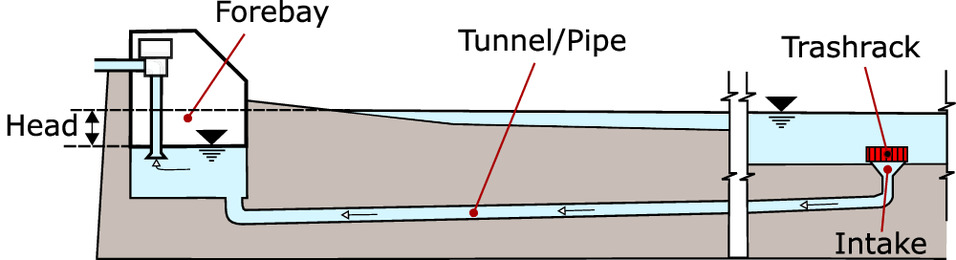
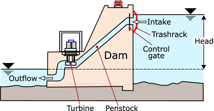
Intakes in the first two types are usually connected to a forebay (also referred to as a wet well) with water pumped from the forebay. The difference in water-surface elevation between the waterbody and the forebay provides the hydraulic head driving the flow into the forebay. The distance between the intake and forebay is relatively short for shoreline intakes. The distance is longer for offshore intakes, up to two thousand meters and longer, with the flow conveyed to the forebay through tunnels or pipelines located on or beneath the bed of the water body. Dam intakes are directly connected to penstocks which convey the flow to turbines. The difference between the upstream and downstream water-surface elevation provides the hydraulic head driving the flow through the intake. Dam intakes generally have a much greater hydraulic head driving the flow through the intake than shoreline or offshore intakes.
Virtually all intakes, no matter their location, have a trash rack as their most upstream component. Trash racks for shoreline and dam intakes are grates composed of metal bars. Trash racks for submerged intakes can be grates or cylinders made of rugged wire screens. Trash racks prevent debris from entering the intake. They are designed to withstand intense environmental conditions for years at a time with little or no maintenance. The sizes of their openings are set to limit the size of entrained material and protect downstream equipment. Other factors, such as regulations for fish protection and safety, may also determine the size of the trash rack openings (Kempema and Ettema 2016). Trash racks are operationally inaccessible for all offshore intakes and many shoreline and dam intakes as well. Reaching these racks requires boats and divers and is usually done only for periodic inspections and repairs. The trash racks on some shorelines and dam intakes are operationally accessible because they can be reached continuously from shore for mechanical or manual ice removal.
Blockage of water intake by underwater ice formation is the result of the entrainment of supercooled water during a supercooling event. The entrained water cools every surface of the intake and the walls of downstream flow passages and downstream equipment to temperatures less than 0°C. The intake trash rack is the principal component that accumulates ice. Ice can also form on surfaces and equipment downstream of the trash rack such as traveling screens (NRC 1996). There are two different processes that can cause underwater ice to build up on a trash rack: (1) deposition of frazil ice crystals; and (2) in situ growth of platelet crystals. In almost all observed cases, the ice buildup is dominated by one process or the other.
Deposition of Frazil ice
The buildup of frazil ice on the intake trash rack through deposition is the most observed and reported form of underwater ice formation (Fig. 4) (Daly 1991). Deposition is common on intakes located on rivers where the supercooling events produce large volumes of frazil ice. The process of frazil ice deposition on trash rack bars is shown in Fig. 5:
1.
Frazil ice has adhered to the leading edge of a trash rack bar and initiated deposition.
2.
The volume of frazil ice deposited has increased in size and has begun spreading laterally.
3.
The trash rack has become blocked when the frazil ice accumulation has bridged between adjacent bars.
4.
The frazil ice can then be extruded through the trash rack bars by the hydrostatic pressure acting on the rack.
5.
Extrusion proceeds across the full rack thickness.

Fig. 4. Trash racks blocked through frazil ice deposition. The racks have been lifted out of the water for inspection.
(Reprinted from Daly 1991, courtesy of the US Army Corps of Engineers, Cold Regions Research and Engineering Laboratory.)
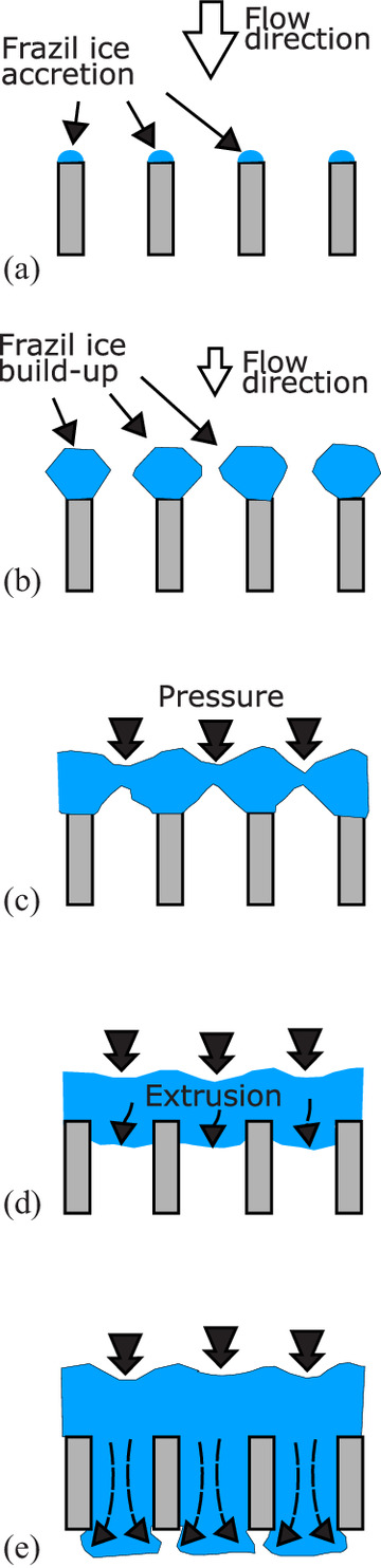
Fig. 5. (Color) Deposition process on trash rack bars, here seen in cross section: (a) initial adhesion; (b) buildup; (c) bridging; (d) extrusion caused by hydrostatic pressure upstream across the rack; and (e) extrusion extends to the full rack thickness.
(Adapted from Daly 1991.)
The head loss across the trash rack increases with time in a very nonlinear manner as the mass of deposited frazil ice increases (Daly 1987; Richard and Morse 2008). Typically, the head loss remains low for a relatively long period after the accumulation process has started and increases rapidly immediately before the time of maximum blockage. The deposition of frazil ice is typically not uniform over the entire rack. Rather, it usually starts at the locations with the highest velocity or locations close to the water surface and proceeds to cover the remainder of the rack (Andersson and Andersson 1992; Andersson and Daly 1992). When nearly or fully blocked, trash racks can experience much higher pressures than during normal operation.
In Situ Growth of Platelet Ice
Evidence of platelet ice blocking intakes is limited to underwater videos taken by divers inspecting blocked offshore intakes in the Great Lakes (Fig. 6) (WestShoreWater 2008, 2010). There are few published references to platelet ice blockage of intakes. Examples of platelet ice growth can be seen in Kempema and Ettema (2016) and Chen et al. (2004). The lack of references can be partly explained by the fact that, in practice, all ice formed on intake trash racks tends to be referred to as frazil ice without regard to whether it was deposited or grew in situ. At this time, there is not enough known about the platelet ice formation to develop a diagram of trash rack blockage by platelet ice that is analogous to the diagram of trash rack blockage by deposition shown in Fig. 5. However, it is likely that the various solutions proposed to prevent blockage work equally well for blockages caused by deposition and by platelet ice, and little distinction is made in the discussions in the next section.
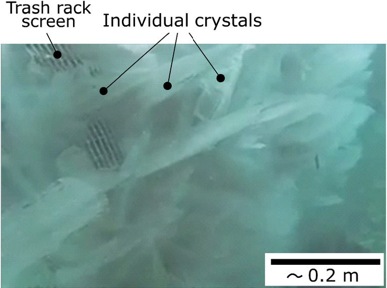
Fig. 6. (Color) Platelet ice on submerged intake.
(Adapted from WestShoreWater 2010.)
Evaluation of Proposed Solutions to Prevent Intake Blockage by Underwater Ice Formation during Supercooling Events
Avoidance
Avoidance can be achieved if a location for the intake can be found that ensures the intake is never exposed to supercooled water. The search for avoidance centers on constructing the intake at water depths unreachable by the supercooled water generated at the surface. In flowing rivers and channels, the fluid turbulence carries the supercooled water to the bottom of the channel, regardless of the depth, and depth provides no protection against the entrainment of supercooled water by the intake.
In lakes and reservoirs, there is a reversed stratification in winter, with the coldest water at the surface and the warmer water located at depth (Farmer and Carmack 1981). The wind creates a mixed layer at the surface with a uniform temperature throughout. This layer will be supercooled during supercooling events. The depth of the mixed layer varies with the size of the lake and its exposure to winds. Water below the mixed layer can be warmer than 0°C, up to a maximum of 3.98°C, the temperature at which freshwater water is at its maximum density. Avoidance is possible if the intake can be located below the depth of the mixed layer. However, the mixed layer can penetrate lakes and reservoirs to surprising depths. Estimates of the mixed layer in Lake Michigan are at least 30 m, which covers the entire near-shore zone where offshore intakes are located (Daly and Ettema 2006). Measurements in Lake Superior have shown mixed layers of nearly 100 m (Assel 1986). Submerged intakes for Deep Lake Cooling Water (DLCW) are designed to be deeper than the mixed layer. Examples are the DLCW for Toronto in Lake Ontario at 83 m depth (Elidas 2003) and Cornell University in Cayuga Lake at 76 m (Cornell University 2022).
Avoidance in lakes and reservoirs is not a viable solution for preventing submerged intake blockage by underwater ice unless the intakes are constructed to depths of sufficient magnitudes. All operators of water intakes not at these depths must be prepared for the possibility of blockage by underwater ice formation.
Prevention
Blockage of a water intake by underwater ice formation can be prevented if supercooled water is kept from entering the intake. There are two approaches to prevention. The first is to warm the water entering the intake so that it is no longer supercooled. The second is the formation of stable ice covers of sufficient size to prevent the production of supercooled water. Ice covers can also warm supercooled water convected beneath them through the transfer of latent heat.
Warming the Intake Flow
Injecting water with a temperature greater than 0°C into the intake flow so that it is no longer supercooled is the most reliable way of preventing intake blockage by underwater ice formation. The warm water must be injected upstream of the intake trash rack. With the supercooling eliminated, ice adhesion is eliminated. This prevents ice accumulation on the intake trash rack and other components by both frazil ice deposition and the in situ growth of platelet ice. It is not likely that all the frazil ice convected with the flow is melted before passing through the intake trash rack. In fact, a considerable portion of the frazil ice may remain in suspension. However, because ice adhesion is prevented, the frazil ice is rendered harmless. Although the remaining convected frazil ice will cool the flow as it melts, it cannot reduce the water temperature below 0°C, the ice/water equilibrium temperature, and cause supercooling. As a result, the warm water protects the intake facility from blockage at every point along its passage through the facility.
The use of heat to warm the intake flow is limited to the shoreline and submerged intakes with facilities that create warm water as a byproduct and can return a portion of this water to the intake. It is rarely practical for facilities that do not have warm water as a byproduct to look elsewhere, although municipal water, groundwater, and other sources have been discussed. (For a review of alternative heat sources, see Morse and Quach 2002.)
The design of a warming system starts with an estimate of the required temperature rise for the intake flow. The temperature rise must be conservatively estimated to ensure it is sufficient to offset the supercooling with some margin for safety. The required flow rate of the warm water supplied to the intake can be found using a simple heat balance based on the temperature rise sought for the intake flow, the intake flow rate, and the temperature of the warm water supply at the intake (Daly 1991). The design of the warm water diffusers upstream of the intake should ensure that all the warm water is entrained by the intake and is distributed more or less uniformly across the intake opening. Typically, the warm water supply is turned on at the beginning of the winter season and supplied continuously throughout the winter.
Ice Cover Formation
If a source of warm water is not available, an alternative is the formation of stable ice covers of sufficient size to prevent the production of supercooled water in the waterbody supplying the intake. As pointed out previously, stable ice covers prevent the production of supercooled water by insulating the water surface and stopping heat transfer from the water to the atmosphere. Stable ice covers also warm supercooled water convected beneath the covers through the transfer of latent heat from the underside of the cover (Ashton 1986). Many intakes in northern regions are protected from supercooled water by the naturally occurring presence of stable ice covers through part, if not most, of the winter (Giffen 1973; Logan 1974; Foulds and Wigle 1977; Billfalk 1992; Daly 2013; Patel and Overton 2014). Ice cover formation is not a completely reliable solution for preventing blockage. It reduces the number of supercooling events, but it cannot entirely end their occurrence. Supercooling events can still occur before an ice cover forms and after the ice cover is no longer in place.
Ice cover formation for blockage prevention is practical only for intakes where the tools for ice cover formation can be applied. These tools include modification of the hydraulic conditions to reduce the flow velocity (Murphy 1909; Devik 1964; Rundgren 1970; Billfalk 1992) and/or the use of ice control structures (ICS) to promote and retain an ice cover (Perham 1981; Tuthill 1995; Abdelnour 2001). In almost all cases, operators of shoreline and submerged intakes cannot form ice covers for blockage prevention. Those located on lakes and reservoirs lack tools for ice cover formation, and those located on flowing rivers generally do not have the scope of operation to modify the river conditions or install ICS. Hydroelectric dams located on rivers have the most potential to promote and retain ice cover. That capacity is determined by the physical capabilities of the dam to control discharges and stages, the possession of the relevant regulatory authority, as well as other considerations. ICS may be effective even if the operators cannot modify the hydraulic conditions. Booms, which are the ICS almost exclusively used in practice, collect and retain drifting ice under a (somewhat limited) range of hydraulic conditions. Other more experimental approaches, such as frazil collector lines (Perham 1981; Sahlberg 1990) and wire mesh or nets (Foltyn 1990; Billfalk 1992), have been successfully tested in the field but are not used in practice.
The use of artificial materials such as Styrofoam in the place of ice covers has been proposed and tested (Mussalli and Budziak 1981). Artificial materials, however, are not practical for preventing intake blockage. Logistical considerations usually limit the surface area covered by this material to only a small fraction of the open water area generating supercooled water. Also, supercooled water convected beneath the artificial material is not as effectively warmed compared to convection beneath ice covers.
Mitigation
Mitigation broadly addresses modifications to the intake operation or the intake structure so that the intake does not become completely blocked during a supercooling event. Modifications to the intake operation have focused exclusively on intake flow reduction. Modifications to the intake structure have focused on developing trash racks that, by their very design, do not become blocked through frazil ice deposition and the reduction or elimination of ice adhesion to the trash rack bars using coatings, alternative materials, heat, or insulation.
Intake Flow Reduction
Intake flow reduction during a supercooling event is a mitigation operation that is sometimes tried (Daly and Ettema 2006). However, flow reduction cannot prevent blockage. Blockages will occur no matter the magnitude of the intake flow. This is because frazil ice and supercooled water are entrained by the intake regardless of the flow velocity. At best, reducing the intake flow extends the length of time until blockage—it does so by reducing the arrival rate of frazil ice. In the experience of the authors, intake flow reduction is generally tried to provide minimum flow to critical facilities during blockage. Unfortunately, at the point where the blockage is detectable, little time will remain before complete blockage occurs, regardless of the intake flow rate.
Trash Rack Design
Proposed modifications to the intake structure have focused on blockage caused by deposition of frazil ice on trash racks composed of bars. All modifications to the trash rack design attempted to prevent the initiation of the frazil ice deposition process shown in Fig. 5, or at the least, to slow down its development.
One design method has been to look for alternative leading-edge shapes for the trash rack bars to reduce or eliminate frazil ice deposition (Aleinikov et al. 1972; Gemperline 1990). Laboratory tests of round, rectangular, and pointed bars found “that the accumulation of ice on intake trash racks is insensitive to the shapes of the bars” (Andersson and Daly 1992). There is also no evidence outside the laboratory that alternative shapes make any difference.
Another aspect of trash rack design that has drawn interest is increasing the spacing between the trash rack bars. There are several reasons why this approach has not been successful. The first is regulatory: increasing the bar spacing runs counter to the current trend of new regulations, which decrease the spacing between trash rack bars in response to environmental concerns, especially fish passage (Kempema and Ettema 2016). The second is safety. Increasing the bar spacing allows larger debris to enter the intake and potentially cause damage to downstream facilities. This is especially true of complete removal of the intake trash rack. In almost all cases, complete removal of the intake trash rack is a major modification of the intake that degrades its safe operation and is rarely a viable solution for intake blockage by underwater ice. Another reason is the lack of evidence that increasing the bar spacing can effectively prevent intake blockage. In theory, the time required for the blockage to occur should be proportional to the bar spacing. This can be seen in Fig. 5(c), which shows that, for bridging to occur, the volume of frazil ice deposited on the trash rack must increase as the bar spacing increases. Given a constant arrival rate of frazil ice, the time until bridging must increase as the spacing increases. However, there is no known bar spacing that increases the time until blockage enough to outlast a supercooling event and prevent complete blockage. There is also no evidence that there exists a critical spacing beyond which bridging cannot occur.
In summary, there is no evidence that mitigation of blockage caused by frazil ice deposition on intake trash racks can be achieved through trash rack design in and of itself.
Trash Rack Ice Adhesion
Three approaches are discussed: coatings and alternate materials, heating, and insulation.
Coatings and Alternate Materials
The use of coatings and alternative materials to reduce ice adhesion has been a topic that has drawn interest for many years (Michel 1963; Williams 1968; Giffen 1973) and has been explored in laboratory tests of model trash racks (Mussalli et al. 1987) and in field tests of intake trash racks (Andersson and Andersson 1992). Briefly, coatings and alternative materials applied to or used for trash rack bars could successfully prevent blockage if their ice adhesion were less than the removal stresses developed at the interface between the trash rack bar and the accumulated ice. Ice adhesion of many coatings and alternate materials has been evaluated in the laboratory (Mulherin and Haehnel 2003). For a discussion of different types of ice adhesion testing in the laboratory, see Rønneberg et al. (2019), Lovell et al. (2021), and others. However, the geometry, method of stress application, and temperature of laboratory tests are very different than the case of trash rack blockage and the applicability of the laboratory tests has not been clearly established.
Laboratory tests made at −10°C show that some coatings and alternative materials have much less ice adhesion than the metals that are typically used to construct trash racks. For example, the ice adhesion of bare carbon steel and bare aluminum is roughly around 1,500 kPa, while the ice adhesion of Teflon and ultrahigh-molecular-weight polyethylene is 240 and 300 kPa, respectively (Mulherin and Haehnel 2003). While the impact of temperature on ice adhesion has been described in broad terms (Makkonen 2012), the applicability of laboratory tests, done at −10°C to the temperature range found during supercooling events, has not been directly addressed. Hence, it is not clear what the ice adhesion values would be at the typical trash rack temperatures during a supercooling event. The existing data do not rule out that the ice adhesion, while reduced, could still be considerable.
Estimating the removal stresses is equally problematic. The principal forces acting on frazil ice deposits that could generate removal stresses are the buoyancy of the deposited frazil ice, hydrostatic pressure acting on the bridged portions of a partially blocked trash rack, and the drag from the flowing water. The buoyancy force acting on deposited frazil with a porosity of 0.4 is estimated to produce a shear stress of 0.005 kPa per centimeter of deposition thickness (Andersson and Daly 1992). Even a relatively thick deposit of 10–20 cm in thickness would only produce a stress of 0.05–0.1 kPa. The removal stress produced by hydrostatic pressure depends on the spacing and depth of the trash rack bars and the degree of blockage of the trash rack. It does not seem likely that the hydrostatic pressure could produce a shear stress of more than about 10 kPa. The forces induced by both the buoyant and hydrostatic pressures are probably far below the ice adhesion levels that even the best coatings and alternative materials could achieve. The removal stress created by water drag is difficult to estimate, given that the flow velocity is perpendicular to the bar edges and the somewhat complicated geometry of the frazil ice deposit, as shown in Fig. 5. Hence, it is not clear that water drag could produce stresses sufficient to remove frazil ice deposits, even at the low ice adhesion values of coatings and alternative materials.
In summary, it would require a very optimistic interpretation of the existing ice adhesion data to conclude that coatings and alternative materials could be effective in preventing intake blockage. At the present time, there is no evidence that coatings and alternative materials can provide reliable protection against blockage.
Heating
Ice adhesion to trash rack bars can be reliably prevented by maintaining the bar surface at a temperature greater than 0°C. Logan (1974) reviewed procedures for estimating the power requirements per unit bar length for a given surface temperature based on the bar shape, flow velocity, and thermal properties of water. Logan suggested that a surface temperature of 0.22°C was adequate if maintained. Logan’s analysis assumed that the entire outer circumference of the bar was heated. Daly et al. (1992) demonstrated in a field test that heating only the upstream leading edge of a rectangular bar prevented ice accumulation on the trash rack. They also noted that ice deposits on unheated portions of the trash rack and intake could grow to cover heated portions. Heating trash rack bars in practice is a complicated undertaking, especially for offshore intakes, and a variety of approaches have been tried or suggested (Ruths 1924; Samsioe 1924; Reid 1928; Logan 1974; Gevay and Erith 1979; Billfalk 1987; Daly et al. 1992; Artola and Garcerán 2014).
Insulation
Many shoreline and dam intakes have trash racks that extend out of the water, thereby exposing a part of each trash rack bar to frigid air. Insulating the exposed portions has been put forward as a means of improving the intake performance during supercooling events (Devik 1964; Gemperline 1990). Insulating the exposed portions may marginally improve the intake performance by preventing the formation of a collar of ice at the immediate water surface. However, the efficient heat transfer of moving water ensures that ice adhesion to the underwater portions of the bars will still occur during supercooling events regardless of the presence of insulation, or the lack of it, on the exposed portion of the bars. As a result, intake blockage can still occur. It is clear that insulating exposed portions of the trash rack bars is not a reliable means of preventing trash rack blockage.
Remediation
Remediation refers to the removal of underwater ice from the intake components after it has formed and before the intake is completely blocked. The common approach to remediation is the mechanical removal of deposited frazil ice through the raking of operationally accessible trash racks. There seems to be little literature on this approach—see Radhuber (2008) for an overview. Based on author experience, raking can be a reliable means of preventing intake blockage. It is almost exclusively done at dam intakes on rivers that carry a significant woody debris load. Both manual and mechanical raking are used:
1.
Manual raking is typically done at small, run-of-river hydroelectric facilities. Problems faced in manual raking include safety and other issues that arise from personnel working during late-night hours in cold, wet conditions.
2.
Mechanical raking is done for larger dam intakes where the trash rack bars extend above the water surface. Mechanical rakes are installed to remove woody debris and other plant matter and then applied to remove frazil ice with little or no modifications. Mechanical problems can arise when hard ice forms on the rake mechanisms as they move from being completely submerged to the frigid air.
Other more ad hoc approaches of remediation have been tried, including trash rack vibration (Mussalli et al. 1987), dynamite blasting and air blasting of underwater trash racks (Giffen 1973), and other techniques. These approaches are not reliable means of preventing frazil ice blockage and are little used, except during emergencies.
Management
Management is accommodating blockages when practical countermeasures for blockage are not available. The three parts of management are detection, damage prevention, and restart.
Detection
Accommodating blockages starts with detecting an ongoing intake blockage process in sufficient time to allow an orderly shutdown of the facility before the blockage forces a last-minute shutdown. Forecasting supercooling events could provide more lead time, but, in practice, forecasting supercooling events has proven to be a challenging task. This is true for lakes and reservoirs, where winds can abruptly change the surface ice conditions in ways that are difficult to predict (Daly and Kempema 2010), and for rivers and streams, even though simulation tools are available (Chen et al. 2006; Blackburn and She 2019).
Detection for most intakes consists of water level alarms. Shoreline or submerged intakes typically have forebay alarms. Dams typically have water level alarms in the intake downstream of the trash rack and/or alarms to monitor turbine performance. Water level alarms are usually set at the minimum levels needed for the safe operation of pumps and turbines. The water level drops as the headloss across the trash rack increases due to the accumulation of ice on the trash rack bars. The intake operators are alerted to the problem when the water level reaches the alarm level. Unfortunately, this provides a rather late time of detection because at this point the intake blockage processes will have been going on for some time, and little time may remain before complete blockage. Nonetheless, many intake operators have learned through experience to shut down their facilities in an orderly fashion using water level alarms.
Alternative detection approaches have been suggested that have the potential for earlier detection than a forebay water level alarm. These include monitoring water temperature and direct ice detection based on acoustic (Richard and Morse 2008), mechanical (Daly and Rand 1990) or electronic means (Yankielun and Gagnon 1999; Artola and Garcerán 2014). These alternative approaches are not used in practice. This is largely due to the lack of commercially available equipment that has the required sensitivity and capability to operate under the harsh conditions found at the relatively remote locations of the water intakes.
Damage Prevention
Management implies that intakes can become blocked by underwater ice without suffering damages. Blockages stress intakes primarily by creating differential pressures across the intake trash rack that are greater than what the racks experience under normal operation. Trash racks can be damaged if they are not designed to withstand these pressures. In the case of shoreline and dam intakes, the maximum differential pressure occurs when the trash rack is completely blocked and the downstream side of the trash rack is completely drained. In the experience of the authors, most shoreline and dam intakes have trash racks designed to withstand these high-pressure events. As a result, these sites can be blocked with little or no damage to their trash racks.
Submerged intakes may be more vulnerable to damages, given the difficulties in estimating the maximum differential pressure that can occur. There are few reports about damages to submerged intakes. Carey (1979) includes a brief description of a submerged intake “totally demolished” due to a “partial vacuum caused by frazil ice buildup.”
Restart
Restarting the facility as soon as possible after shutdown is an important part of management. In most cases, the facility can be restarted after the supercooling event ends and the ice buildup on the intake trash rack sheds spontaneously. Because the duration of supercooling events is highly variable, the time for the intake to clear can also be highly variable. An example of the variability in supercooling event durations can be seen in the 93 supercooling events observed by Kalke et al. (2019), where the average duration was 17 h, and the maximum duration was five days. The optimistic rule of thumb is to wait for daylight to bring sufficient sunlight to warm the water and end the supercooling event.
Actions taken to hasten restarting include backflushing and raking. Raking can be used at operationally accessible trash racks where it was not done during the blockage process, typically at facilities that were not staffed at night. Backflushing is used to remove accumulated ice on the trash racks of submerged intakes. It is limited to facilities that have the capability to reverse the flow through the intake pipeline and is usually accomplished by pumping water into the forebay. It is likely that heat conduction from the walls of the pipe and forebay into the water, combined with the above 0°C temperature of the water added into the forebay, raises the temperature of the backflush water enough to remove accumulated ice on the trash rack.
Discussion
The reliable solutions for preventing blockage, warming the intake flow, the formation of stable ice covers, heating the trash rack bars, and mechanical removal by raking, are not new. These solutions have been employed and discussed for 100 years or more, and in the case of raking, much longer. The lack of development of a broader range of reliable solutions results from two unresolved issues of underwater ice formation on intake trash racks. The first issue is the development of practical means for significantly reducing or eliminating trash rack ice adhesion during supercooling events without the application of heat. The mitigation approaches that have attempted to do this, such as trash rack design, coatings, use of alternative materials, and insulation, have not been successful to date. Development of icephobic coatings is a burgeoning research area that remains continually promising. However, the intake environment is challenging because the stresses that can remove the underwater ice from the intake trash rack are quite small, as discussed. This suggests that this issue will not be resolved unless substantial reductions in ice adhesion are achieved. The second issue is the difficulties in the mechanical removal of underwater ice at operationally inaccessible intakes. The inherent problems of installation, operation, monitoring, and maintaining mechanical removal equipment at inaccessible intakes have not been overcome to date. These problems limit mechanical removal to raking at accessible intakes. Until there is a significant breakthrough to resolve either of these issues, the range of reliable solutions is not likely to expand.
Conclusion
This paper evaluates proposed solutions for preventing water intake blockage by underwater ice formation during supercooling events. In this context, underwater ice formation means deposition of frazil ice and growth of platelet ice. The various proposed solutions for preventing blockage are collected into four broad categories and evaluated. These categories are avoidance, mitigation, prevention, and remediation. The following reliable solutions for preventing blockage are described.
Warming the Intake Flow
Injecting water with a temperature greater than 0°C into the intake flow so that it is no longer supercooled is the most reliable way of preventing intake blockage by underwater ice formation. The warm water must be injected upstream of the intake trash rack. This approach is generally limited to shorelines and submerged intakes with facilities that create warm water as a byproduct and can return a portion of this water to the intake.
Formation of Stable Ice Covers
Stable ice covers prevent the production of supercooled water by insulating the water surface and stopping heat transfer from the water to the atmosphere. Stable ice covers also warm supercooled water convected beneath the covers through the transfer of latent heat from the underside of the cover. Ice cover formation to prevent intake blockage is practical only for intakes where the tools for ice cover formation can be applied.
Heating the Trash Rack Bars
Ice adhesion to trash rack bars can be reliably prevented by maintaining the bar surface at a temperature greater than 0°C. Heating trash rack bars in practice is a complicated undertaking, especially for offshore intakes, and various approaches have been tried or suggested.
Removal of Underwater Ice by Raking
Mechanical or manual raking of the intake trash racks to remove deposited frazil ice is a reliable means of preventing blockage.
Key Issues
The two key issues currently limiting the development of new solutions are (1) the lack of coatings or alternative materials that can significantly reduce ice adhesion without using heat, and (2) mechanical removal of underwater ice at operationally inaccessible intakes.
Management
In addition, a strategy, management, addresses intake operation when practical measures for blockage prevention are not available. Management accommodates periodic blockages into the operation of facilities through blockage detection, damage prevention, and quick and efficient restarts. Improvements in forecasting supercooling events based on ice formation models driven by meteorological and hydrologic forecasts would provide an additional lead time for orderly shutdowns of facilities before the blockage forces a last-minute shutdown.
Data Availability Statement
No data, models, or code were generated or used during the study.
References
Abdelnour, R. 2001. “Ice booms in rivers; lessons learned and the development of reliable solutions.” In Proc., 11th Workshop on the Hydraulics of Ice Covered Rivers. Ottawa: Committee on River Ice Processes and the Environment (CRIPE).
Aleinikov, S. M., R. A. Gutkin, and V. M. Chesnokov. 1972. “Winter operation of heating systems of hydromechanical equipment of hydraulic structures.” In Proc., 2nd Int. Symp. on Ice and its Action on Hydraulic structures. Madrid, Spain: International Association for Hydro-Environment Engineering and Research (IAHR).
Andersson, A., and L. O. Andersson. 1992. “Frazil ice formation and adhesion on trash racks.” In Proc., 11th Int. Symp. on Ice. Madrid, Spain: International Association for Hydro-Environment Engineering and Research (IAHR).
Andersson, A., and S. F. Daly. 1992. Laboratory investigation of trash rack freezeup by frazil ice. Rep. No. 92-16. Hanover, NH: US Army Cold Regions Research and Engineering Laboratory.
Artola, I. C., and A. L. Garcerán. 2014. Detection of frazil ice at water intakes at Träbena power station. Sweden: Mechanical Engineering, Univ. of Skövde.
Ashton, G. D. 1986. River and lake ice engineering. Littleton, CO: Water Resources Publications.
Assel, R. A. 1986. “Fall and winter thermal structure of Lake Superior.” J. Great Lakes Res. 12 (4): 251–262. https://doi.org/10.1016/S0380-1330(86)71725-5.
Barnes, H. T. 1906. Ice formation with special reference to anchor-ice and frazil. New York: Wiley.
Barrette, P. D. 2021. “Understanding frazil ice: The contribution of laboratory studies.” Cold Reg. Sci. Technol. 189: 103334. https://doi.org/10.1016/j.coldregions.2021.103334.
Baylis, J. A., and H. H. Gerstein. 1948. “Fighting frazil ice at a waterworks.” Eng. News-Rec. 140: 562–565.
Billfalk, L. 1987. Ice problems in hydro power plants. Rep. No. U(L) 1987/15. Älvkarleby, Sweden: Vattenfall Älvkarlebylboratoriet.
Billfalk, L. 1992. “Ice effects and control for hydro power production.” In Proc., 11th Int. Symp. on Ice. Madrid, Spain: International Association for Hydro-Environment Engineering and Research (IAHR).
Blackburn, J., and Y. She. 2019. “A comprehensive public-domain river ice process model and its application to a complex natural river.” Cold Reg. Sci. Technol. 163: 44–58. https://doi.org/10.1016/j.coldregions.2019.04.010.
Carey, K. L. 1979. Ice blockage of water intakes. NUREG/CR-0548. Washington, DC: Division of Site Safety and Environmental Analysis, Office of Nuclear Reactor Regulation, US Nuclear Regulatory Commission.
Chen, F., H. T. Shen, and N. C. Jayasundara. 2006. “A one-dimensional comprehensive river ice model.” In Proc., 18th Int. Symp. on Ice. Madrid, Spain: International Association for Hydro-Environment Engineering and Research (IAHR).
Chen, Z., R. Ettema, and Y. Lai. 2004. “Ice-tank and numerical study of frazil Ingestion by submerged intakes.” J. Hydraul. Eng. 130 (2): 101–111. https://doi.org/10.1061/(ASCE)0733-9429(2004)130:2(101).
Cornell University. 2022. “How lake source cooling works.” Accessed September 7, 2022. https://fcs.cornell.edu/departments/energy-sustainability/utilities/cooling-home/cooling-production-home/lake-source-cooling-home/how-lake-source-cooling-works.
Daly, S. F. 1984. Frazil ice dynamics. Monograph 84-1. Hanover, NH: US Army Cold Regions Research and Engineering Laboratory.
Daly, S. F. 1987. “Modeling trash rack freezeup by frazil ice.” In Proc., 1st Int. Symp. on Cold Regions Heat Transfer, 101–106. Edmonton, AB: American Society of Mechanical Engineers.
Daly, S. F. 1991. Frazil ice blockage of intake trash racks. Technical Digest 91-1. Hanover, NH: US Army Cold Regions Research and Engineering Laboratory.
Daly, S. F. 2013. “Frazil ice.” In River ice formation, edited by S. Beltaos, 107–134. Edmonton, AB: Committee on River Ice Processes and the Environment, CGU-HS.
Daly, S. F., and R. Ettema. 2006. “Frazil ice blockage of water intakes in the Great Lakes.” J. Hydraul. Eng. 132: 814–824. https://doi.org/10.1061/(ASCE)0733-9429(2006)132:8(814).
Daly, S. F., F. D. Haynes, D. E. Garfield, and C. H. Clark. 1992. “Field test of a surface heated trash rack to prevent frazil ice blockage.” In Proc., 11th Int. Symp. on Ice. Madrid, Spain: International Association for Hydro-Environment Engineering and Research (IAHR).
Daly, S. F., and E. Kempema. 2010. “Environmental conditions during frazil ice blockage of a water intake in Lake Michigan.” In Proc., 20th Int. Symp. on Ice. Madrid, Spain: International Association for Hydro-Environment Engineering and Research (IAHR).
Daly, S. F., and J. H. Rand. 1990. “Development of an underwater frazil-ice detector.” Cold Reg. Sci. Technol. 18: 77–82. https://doi.org/10.1016/0165-232X(90)90039-Y.
Devik, O. 1964. “Present experience on Ice problems connected with the utilization of water power in Norway.” J. Hydraul. Res. 2: 25–40. https://doi.org/10.1080/00221686409500070.
Dorsey, N. E. 1948. “The freezing of supercooled water.” Trans. Am. Philos. Soc. 38 (3): 247–328. https://doi.org/10.2307/1005602.
Elidas, C. 2003. “Deep lake water cooling, a renewable technology.” Electrical Line Magazine, May/June, 26–28.
Ettema, R., M. F. Karim, and J. F. Kennedy. 1984. Frazil ice formation. Rep. No. 84-18. Hanover, NH: US Army Cold Regions Research and Engineering Laboratory.
Farmer, D. M., and E. Carmack. 1981. “Wind mixing and restratification in a lake near the temperature of maximum density.” J. Phys. Oceanogr. 11: 1516–1533. https://doi.org/10.1175/1520-0485(1981)011%3C1516:WMARIA%3E2.0.CO;2.
Foltyn, E. P. 1990. Laboratory and field tests of a wire mesh frazil collector. Special Rep. No. 90-35. Hanover, NH: US Army Cold Regions Research and Engineering Laboratory.
Foulds, D. M. 1974. “Ice problems at water intakes.” Can. J. Civ. Eng. 1: 137–140. https://doi.org/10.1139/l74-012.
Foulds, D. M., and T. E. Wigle. 1977. “Frazi—The invisible strangler.” J. Am. Water Works Assn. 69: 196–199. https://doi.org/10.1002/j.1551-8833.1977.tb06714.x.
Gemperline, E. J. 1990. “Considerations in the design and operation of hydro power intakes.” In Cold regions hydrology and hydraulics: A state of the practice report, edited by R. D. Crissman and W. L. Ryan., 517–556. Reston, VA: ASCE.
Gevay, B. J., and H. A. Erith. 1979. “Electric heating of intake trash racks at Twin Falls, Labrador.” Can. J. Civ. Eng. 6 (2): 319–324. https://doi.org/10.1139/l79-032.
Ghobrial, T. R., and M. R. Loewen. 2021. “Continuous in situ measurements of anchor ice formation, growth, and release.” Cryosphere 15: 49–67. https://doi.org/10.5194/tc-15-49-2021.
Ghobrial, T., A. Pierre, and B. Morse. 2021. “Field measurements of frazil ice accumulation at a water intake on the Mille-Iles River, Québec.” In Proc., 21st Workshop on the Hydraulics of Ice Covered Rivers. Committee on River Ice Processes and the Environment (CRIPE). http://cripe.ca/en/publications/proceedings/21.
Giffen, A. V. 1973. The occurrence and prevention of frazil ice blockage at water supply intakes: A literature review and field survey. Toronto: Ontario Ministry of the Environment.
Hammar, L., and H. T. Shen. 1995. “Frazil evolution in channels.” J. Hydraul. Res. 33 (3): 291–306. https://doi.org/10.1080/00221689509498572.
Henshaw, H. 1887. “Frazil ice: On its nature, and the prevention of its action on preventing floods.” Trans. Can. Soc. Civ. Eng. 1 (1): 1–23.
Kalke, H., V. McFarlane, T. R. Ghobrial, and M. R. Loewen. 2019. “Field measurements of supercooling in the North Saskatchewan River.” In Proc., 20th Workshop on the Hydraulics of Ice Covered Rivers. Ottawa: Committee on River Ice Processes and the Environment (CRIPE).
Kempema, E. W., and R. Ettema. 2016. “Fish, ice, and wedge-wire screen water intakes.” J. Cold Reg. Eng. 30 (2): 04015004. https://doi.org/10.1061/(ASCE)CR.1943-5495.0000097.
Kempema, E. W., E. Reimnitz, and P. W. Barnes. 2001. “Anchor-ice formation and ice rafting in southwestern Lake Michigan, U.S.A.” J. Sediment. Res. 71 (3): 346–354. https://doi.org/10.1306/2DC40948-0E47-11D7-8643000102C1865D.
Logan, T. H. 1974. Prevention of frazil ice clogging of water intakes by application of heat. Rep. No. REC-ERC-74-15. Denver, CO: US Bureau of Reclamation.
Lovell, A. R., G. R. Hoch, C. J. Donnelly, J. M. Hodge, R. B. Haehnel, and E. Asenath-Smith. 2021. Shear and tensile delamination of ice from surfaces: The Ice Adhesion Peel Test. Rep. No. ERDC/CRREL TN-21-1. Hanover, NH: US Army Engineer Research and Development Center.
Makkonen, L. 2012. “Ice adhesion—Theory, measurements and countermeasures.” J. Adhes. Sci. Technol. 26: 413–445. https://doi.org/10.1163/016942411X574583.
Michel, B. 1963. “Theory of formation and deposit of frazil ice.” In Proc., 20th Annual Eastern Snow Conf. https://www.easternsnow.org/esc-1963.
Michel, B. 1971. Winter regime of rivers and lakes. Rep. No. M III-B1a. Hanover, NH: US Army Cold Regions Research and Engineering Laboratory.
Morse, B., and T.-T. Quach. 2002. “Preventing frazil ice accumulations at hydroelectric facilities.” In Proc., 16th Int. Symp. on Ice. Madrid, Spain: International Association for Hydro-Environment Engineering and Research (IAHR).
Mulherin, N. D., and R. B. Haehnel. 2003. Progress in evaluating surface coatings for icing control at corps hydraulic structures. Technical Note 03-4. Hanover, NH: US Army Cold Regions Research and Engineering Laboratory.
Murphy, J. 1909. “The ice question—as it affects Canadian waterpower—with special reference to frazil ice and anchor ice.” In Proc., Transactions of the Royal Society of Canada, 143–177. Ottawa: Royal Society of Canada.
Mussalli, Y. G., and B. Budziak. 1981. “Solving icing problems at power plant intakes.” Power Eng. 85: 58–59.
Mussalli, Y. G., L. S. Gordon, and S. F. Daly. 1987. “Frazil ice control using electromechanical vibrators and ice-resistant coatings.” In Proc., Water Power ‘87. Reston, VA: ASCE.
NRC (Nuclear Regulatory Commission). 1996. Degradation of cooling water systems due to icing. NRC Information Notice 96-36. Washington, DC: US Nuclear Regulatory Commission, Office of Nuclear Reactor Regulation.
Osterkamp, T. E. 1977. “Frazil-Ice nucleation by mass-exchange processes at the air–water interface.” J. Glaciol. 19 (81): 619–627. https://doi.org/10.3189/S0022143000215529.
Osterkamp, T. E., and J. P. Gosink. 1983. “Frazil ice formation and ice cover development in interior Alaska streams.” Cold Reg. Sci. Technol. 8 (1): 43–56. https://doi.org/10.1016/0165-232X(83)90016-2.
Parkinson, F. 1987. “Frazil ice problems at trash racks.” In Proc., EPRI/CEA Conf., 150–159.
Patel, S., and T. Overton. 2014. “Prepare your renewable plant for cold weather operations.” Power 158: 1–10.
Perham, R. E. 1981. “Tests of frazil collector lines to assist ice cover formation.” Can. J. Civ. Eng. 8: 442–448. https://doi.org/10.1139/l81-058.
Radhuber, W. 2008. “Trashrack cleaning, the past—the present—the future.” In Proc., 15th Int. Seminar on Hydropower Plants. Vienna, Austria: Vienna Institute for Technology.
Reid, C. R. 1928. “Electric heating of rack-bars in hydroelectric plants.” Eng. J. 263–265.
Richard, M., and B. Morse. 2008. “Multiple frazil ice blockages at a water intake in the St. Lawrence River.” Cold Reg. Sci. Technol. 53: 131–149. https://doi.org/10.1016/j.coldregions.2007.10.003.
Rønneberg, S., J. He, and Z. Zhang. 2019. “Standardizing the testing of low ice adhesion surfaces.” In Proc., Int. Workshop on Atmospheric Icing of Structures. Reykjavik, Iceland: International Workshop on Atmospheric Icing of Structures (IWAIS).
Rundgren, L. 1970. “A philosophy on tackling ice problems.” In Proc., 1st Int. Symp. on Ice and Its Action on Hydraulic Structures. Madrid, Spain: International Association for Hydro-Environment Engineering and Research (IAHR).
Ruths, A. 1924. “Ice troubles in Norwegian power plants.” In Proc., Transportation 1st World Power Conf., 771–787. London.
Sahlberg, J. 1990. “Frazil ice problems at Stornorrfors water power plant in the Ume River.” In Proc., 10th Int. Symp. on Ice. Madrid, Spain: International Association for Hydro-Environment Engineering and Research (IAHR).
Samsioe, A. F. 1924. “Measures taken in Sweden against ice troubles at water power plants.” In Proc., Transportation 1st World Power Conf., 806–811. London.
Schaefer, V. J. 1950. “The formation of frazil and anchor ice in cold water.” Trans. Am. Geophys. Union 31: 885–893. https://doi.org/10.1029/TR031i006p00885.
Tuthill, A. 1995. Structural ice control: Review of existing methods. Special Rep. No. 95-18. Hanover, NH: US Army Cold Regions Research and Engineering Laboratory.
WestShoreWater. 2008. “Frazil ice on Lake Michigan intake screen.” Accessed May 20, 2022. https://www.youtube.com/watch?v=COMV3UEE47A.
WestShoreWater. 2010. “Frazil ice on Lake Michigan water utility intake.” Accessed May 20, 2022. https://www.youtube.com/watch?v=McG-CFtJnIM.
Wigle, T. E. 1970. “Investigations into frazil, bottom ice, and surface ice formation in the Niagara River.” In Proc., 1st Int. Symp. on Ice and its Action on Hydraulic Structures. Madrid, Spain: International Association for Hydro-Environment Engineering and Research (IAHR).
Williams, G. P. 1968. “Adhesion of frazil ice to underwater structures.” In Proc., 24th Annual Eastern Snow Conf. https://www.easternsnow.org/esc-1967.
Yankielun, N. E., and J. J. Gagnon. 1999. “Laboratory tests of a time-domain reflectometry system for frazil ice detection.” Can. J. Civ. Eng. 26 (2): 168–176. https://doi.org/10.1139/l98-058.
Ye, S. Q., and J. Doering. 2004. “Simulation of the supercooling process and frazil evolution in turbulent flows.” Can. J. Civ. Eng. 31: 915–926. https://doi.org/10.1139/l04-055.
Information & Authors
Information
Published In

Journal of Cold Regions Engineering
Volume 37 • Issue 1 • March 2023
Copyright
This work is made available under the terms of the Creative Commons Attribution 4.0 International license, https://creativecommons.org/licenses/by/4.0/.
History
Received: Apr 29, 2022
Accepted: Sep 16, 2022
Published online: Nov 9, 2022
Published in print: Mar 1, 2023
Discussion open until: Apr 9, 2023
Authors
Metrics & Citations
Metrics
Citations
Download citation
If you have the appropriate software installed, you can download article citation data to the citation manager of your choice. Simply select your manager software from the list below and click Download.
Cited by
- Robert Ettema, Edward W. Kempema, Discussion of “Prevention of Water Intake Blockage by Ice during Supercooling Events”, Journal of Cold Regions Engineering, 10.1061/JCRGEI.CRENG-729, 38, 1, (2024).