Rebar Replacement in Severely Damaged RC Bridge Column Plastic Hinges: Design Criteria and Experimental Investigation
Publication: Journal of Structural Engineering
Volume 149, Issue 3
Abstract
This paper presents a procedure for rehabilitating plastic hinges with damaged/fractured weldable longitudinal rebars in severely damaged reinforced concrete (RC) bridge columns and possible improvements regarding connection protection and plastic hinge development. Damaged/fractured longitudinal rebars are replaced with new rebar segments, and the basis of this approach involves connecting intermediate machined parts to the original longitudinal rebars by welding with an off-the-shelf steel equal angle. The proposed rehabilitation design procedure is based on capacity design principles, with equations that define the new geometries and required ductility, and it is validated experimentally on three -scale RC circular column specimens. Compared with the original columns, the ductility capacity of the rehabilitated columns increased from 39% to 58%, and the energy dissipation (equivalent viscous damping ratio) increased from approximately 50% to 250%. The base shears of the rehabilitated columns were smaller than those of the original columns owing to the reduction in the rebar area; thus, shear failure was avoided, and the demand on the foundation was reduced. The rehabilitation procedure, by adopting a welding connection that is easily performed on site and concentrates the damage in the new rebar segments, promises to be a quick, simple, reliable, and effective means to improve the ductility and shear capacity of RC bridge columns without using mechanical couplers or changing the column dimensions.
Introduction
A simple welding connection system for the replacement of damaged/fractured longitudinal rebars in severely damaged reinforced concrete (RC) columns with new rebar segments, which have reduced diameters in their intermediate parts (machined part) compared with the original rebars, is theoretically and experimentally investigated in this paper. The proposed rehabilitation procedure includes column repair and shear strength upgrading to obtain compliance with structural performance requirement of CEN (2020), whereas flexural strength upgrading is not considered, as in the case of many existing bridge columns that present only shear strength seismic deficiencies due to construction error or old (not seismic design) code.
The present procedure explores the possibility of connecting new rebar segments to the original weldable undamaged rebar ends by a connection system composed of a part from an off-the-shelf steel equal angle; a welding connection is adopted to simplify the on-site process, resolve geometrical problems due to nonalignment of the original rebars, limit the demolishment of the core concrete to the damaged parts only, retain the positions of the plastic hinge thanks to the containment of the welding length, and reduce the uncertainties regarding the bridge capacity after rehabilitation.
That the bars are weldable has a huge connotation for the application of this technique. It is therefore strongly recommended that a chemical analysis of the bars to be replaced is carried out to check their weldability.
Provided that the original rebars are weldable, the rehabilitation process solves the following two crucial aspects of plastic hinge rehabilitation: (1) it develops a simple technique for replacing a damaged/fractured longitudinal rebar even in complicated site conditions; and (2) it preserves the connections to the original rebars from yielding and allows the location of the plastic hinge above the foundation to remain unchanged if not slightly reduced. An additional positive aspect worth mentioning is that the shear demand remains unchanged or is slightly reduced. Finally, to simplify the concrete placement with a positive impact on execution, the hoops are reduced, which is not discussed in this paper.
The paper includes an analytical determination of the geometries of the new rebar segments and of the connections to the original weldable rebars. Also presented, to confirm the design procedure, are experimental tests on three -scale specimens representative of the column of a prototype bridge before and after rehabilitation with rebar segments of different machined lengths and diameters. Finally, the main conclusions are drawn, and open issues for future research are presented.
Literature Review
The typical damages corresponding to different damage states that RC bridge columns experience following earthquakes are as follows: concrete cracking; concrete cover spalling; and yielding, buckling, or fracturing of hoops and/or longitudinal rebars (Vosooghi and Saiidi 2010a, b). Substandard columns (not designed for modern seismic codes) and sometimes standard columns (designed for modern seismic codes) may experience buckling, rebar fracturing, and shear failure (He et al. 2015).
He et al. (2015) classified bridge column rehabilitation as follows: (1) rehabilitation of RC bridge columns without fractured longitudinal rebars; and (2) rehabilitation of RC bridge columns with fractured longitudinal rebars.
The rehabilitation of RC bridge columns without fractured longitudinal rebars usually refers to bridge columns with small to moderate damage; rehabilitation results in adequate strength capacity without external reinforcement systems but obtains reduced stiffness (French et al. 1990; Lehman et al. 2001) or has adequate external reinforcement systems, such as RC jackets (Bett et al. 1988; Kunwar et al. 2021), steel jackets (Chai et al. 1991; Zhang et al. 2021), fiber-reinforced polymer (FRP) jackets (Chang et al. 2004; Elsouri and Harajli 2011; He et al. 2013b, 2014; Li and Sung 2003; Priestley and Seible 1993; Saadatmanesh et al. 1997; Sheikh and Yau 2002; Vosooghi et al. 2008), near-surface mounting (NSM) of carbon fiber–reinforced polymer (CFRP) laminate systems or hybrid CFRP systems (Chellapandian and Prakash 2018), grooving and corner strip-batten reinforcement (Saljoughian and Mostofinejad 2020), and shape memory alloys (SMAs) (Shin and Andrawes 2011), which recover the bridge column strength and often the stiffness as well. Rehabilitation with external RC jackets may require a relatively long time to cure, as well as considerable labor. For the others, reduced stiffness could occur, which is a limitation.
Rehabilitation of RC bridge columns with fractured longitudinal rebars was proposed by Albanesi et al. (2009), Cheng et al. (2003, 2004), Hwang et al. (2021), He et al. (2013a, b, 2016), Lavorato and Nuti (2015), Lavorato et al. (2015, 2017), Lehman et al. (2001), Parks et al. (2016), Rodrigues et al. (2017, 2018), Rutledge et al. (2014), Saiidi and Cheng (2004), Shin and Andrawes (2011), Vosooghi and Saiidi (2013), Wu and Pantelides (2017), Xue et al. (2018), and Yang et al. (2015a, b). These procedures involve the replacement of fractured rebars with other rebars or with external reinforcements in FRP, with or without new external jackets. Some methods include relocation of the plastic hinge. Such rehabilitation procedures can require substantial labor and be time-consuming, with the exception of those that consist of external FRP applications only, which require additional studies to achieve effective strength, ductility, and stiffness.
The closure of one or more bridges can paralyze an entire region (Briseghella et al. 2019; Nuti and Vanzi 2003; Nuti et al. 2010); therefore, there has been growth in new rehabilitation technique proposals for reopening bridges to traffic in a short time (He et al. 2013a, b; Sun et al. 2017; Wu and Pantelides 2018), even with reduced performance (for example, limited to sustaining emergency traffic).
Considering this, an appealing roadmap is the optimization of some rehabilitation procedures of RC bridge columns with fractured longitudinal rebars, such as those proposed by Cheng et al. (2003, 2004), Lehman et al. (2001), Shin and Andrawes (2011), and Yang et al. (2015a), which include fractured rebar replacement and could be grouped with that of Cheng and Mander (1997), which implies the connection of the new rebar segments with the original rebars through mechanical connectors.
Rehabilitation has some important open issues. First, because of the dimensions and stiffness of the mechanical coupler, the plastic hinge is relocated to a position above or below the connection. This may reduce the length of the plastic hinge and increase the shear demand, with unfavorable effects on the displacement capacity of the bridge. Additionally, connecting the new rebar segments with the original rebar in the bridge column may be a complex and difficult process in different real cases (e.g., the operating space to apply the coupler in the case of congested rebar may be insufficient, or rehabilitation could be difficult in the case of an irregular arrangement of the rebars); therefore, alternative connection systems should be evaluated (Kheyroddin et al. 2021). Moreover, with the exception of dog-bone solutions (Cheng and Mander 1997), there could be the risk of unwanted plastic hinge relocation or connection failure due to segment overcapacity.
The present proposal, following those by Cheng and Mander (1997) and Cheng et al. (2003, 2004), localizes the new plastic hinge on the new rebar segments only. The following simplifications are discussed: the segment replacement is realized using a machined rebar, and assembly is realized by means of a connector composed of an off-the-shelf steel equal angle, which is also applicable in the case of congested and/or irregular rebars, with the use of welding.
Rehabilitation Procedure
An RC bridge column is considered with adequate longitudinal rebars but inadequate hoops for confinement and shear (Lavorato et al. 2015) that is damaged by strong seismic action. A method is discussed involving the replacement of damaged/fractured longitudinal rebars with new rebar segments and the use of CFRP wrapping to enhance the shear strength, to provide continuum bracing (which can keep the new machined rebars from buckling) and to allow large hoop spacing in the rehabilitation zone. Alternative transverse reinforcement solutions have been presented by Lavorato et al. (2017) and Xue et al. (2018).
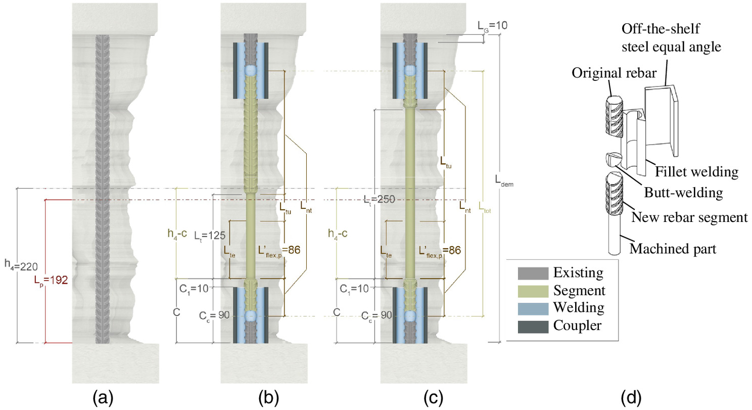
New rebar segments are commercially available. The new rebar segments are connected with the original weldable undamaged rebars by means of an off-the-shelf steel equal angle, to which the ends of the original rebars and new rebar segments are spliced by fillet and butt welding (Fig. 1).
The selected steel equal angle permits the original column geometry to remain unchanged while simplifying the alignment between the original rebars and new rebar segments. The rebars can be welded to the steel equal angle from the exterior of the column. According to the authors’ experience, the rehabilitation operation can be completed in a few days (3 days for the lab specimen). The rehabilitation operation on site could take more time owing to careful design and preparations, including stabilizing the column if needed, taking samples, and conducting mechanical and metallurgical tests. Moreover, it is recommended to wait for concrete to harden before applying CFRP wrapping and opening the bridge to traffic. The large spacing of new hoops and self-compacting concrete (Lavorato and Nuti 2015) simplifies the placement of rehabilitation concrete. Other researchers (He et al. 2013a, b; Wu and Pantelides 2017) have proposed rapid rehabilitation techniques, according to ATC-18 (ATC 1997), with 3–5 days of rehabilitation time. Yang et al. (2015a) used mechanical bar couplers, which imply a reduced cover and require good alignment.
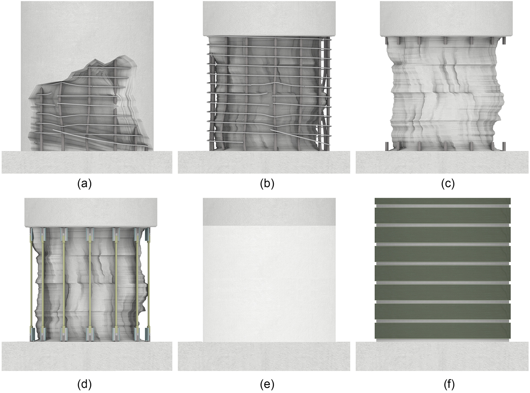
A typical example of severe damage in RC bridge columns damaged by strong seismic action is shown in Fig. 2(a). The rehabilitation technique can be divided into five phases. The damaged longitudinal rebar, hoops, and concrete cover were removed [Fig. 2(b)]. The new rebar segments were connected to the original weldable undamaged rebars with off-the-shelf steel equal angles by fillet and butt welding [Fig. 2(c)]. The new hoops were placed [Fig. 2(d)]. After the application of self-compacting concrete (SCC) [Fig. 2(e)], unidirectional CFRP jacketing was applied [Fig. 2(f)].
There was no axial force during rehabilitation. Even if this is an approximation with respect to possible real cases, it is considered acceptable, as the applied axial force would be smaller than 15% of the residual core column strength. According to the literature (Ferrotto et al. 2018a, b, c), for small preload values, as in the case analyzed, the capacity of the confined column is similar to that obtained without considering the preload. The connection system design and the geometry of new rebar segments are presented in the following sections.
The rehabilitation details for rebar replacement design of the rehabilitated columns (RRs) should be designed on the basis of those of the original columns (ORs). The basis of the procedure is the assumption of equal total top horizontal displacement () before and after rehabilitation, as follows: (for the OR) = (for the RR). The design of the new rebar segment consists of defining the geometry of the connections to the cut original weldable rebars and the diameter () and length () of the machined part of the new rebar segment.
The connector proposed in this paper consists of a steel equal angle to which the original weldable rebars and new rebar segments are connected by fillet welding. The ends of the original weldable rebars and new rebar segments are also butt-welded to reduce the length of the fillet weld (Fig. 1). Therefore, the total length of connector () is as follows:where = original longitudinal rebar diameter in the column; and = gap needed for butt-welding in accordance with rebar welding standards (AWS 2011; MOH 2012). Usually, should be less than ; for simplicity, it can be assumed that is equal to .
(1)
The selection of and can be obtained by considering the following four issues: (a) should be determined considering that the maximum force transmitted by the machined rebar should be smaller than the yield force in the connector and in the original anchoring underneath; (b) the effective machined length () where the new rebar segment undergoes plasticity should be shorter than ; (c) the expected plastic curvature demand () in the plastic hinge after rehabilitation; and (d) the relation between , , and .
Fig. 1 shows that the total length of the new rebar segment () usually depends on the dimensions of the damaged part of the column in the plastic hinge zone. The new rebar segment consists of a central machined part and two nonmachined parts on the two sides, as follows:where = total length of the new rebar segment with no diameter reduction (nonmachined parts). To allow welding the new rebar segment to the off-the-shelf steel equal angles, the shortest is as follows:where = gap between the connector end and the machined start position, which ranges from 5 to 15 mm (Fig. 1).
(2)
(3)
The total length between the column bottom end and the machined start position () is as follows:
(4)
Sometimes part of the connector could enter the foundation. The length of the removed concrete part () will include, in addition to the substitute new rebar segment length (), the portions of original rebars in the columns to weld the steel equal angles (top and bottom), i.e., , and in the upper part only an additional gap length (), which is usually .
The dimensions of the machined part, and , determine the behavior of the column after rehabilitation. This will be correlated with the behavior of the original column. To guarantee that the plastic excursion develops in the new rebar segment, the maximum force of the new rebar segments must be smaller than the resistance of the connectors and of the original rebars.
The relation between , , and can be found by means of capacity design strategy, as follows:where and = yield stress of the connector with the cross-sectional area () and of the original rebar (MPa), respectively; = yield stress of the new rebar segment (MPa); and [squared in Eq. (5) to be applied to ] takes into account the uncertainties regarding the original and new steel material characteristics (in the rebar and steel equal angle) (Forte et al. 2018) and the hardening of the new rebar segment after yielding. For the assumed present application, .
(5)
If , which is easily guaranteed (the connector must be stiff with a large ), then the second term in the parenthesis of min() is the smallest, from Eq. (6), and can be obtained:
(6)
The curvature ductility demand of the RR can be formulated on the basis of the curvature ductility demand of the OR. A model for evaluation is proposed, which holds true for the OR and RR. can be subdivided into four contributions:where = yield displacement of the original column; and = displacement beyond yielding of the original column. Both displacements are contributed by a part due to the column internal deformations, and , and a second part due to the slip into the foundation of the column, and . The two latter variables are determined by the two concentrated rotations at the base, at yielding and beyond yielding.
(7)
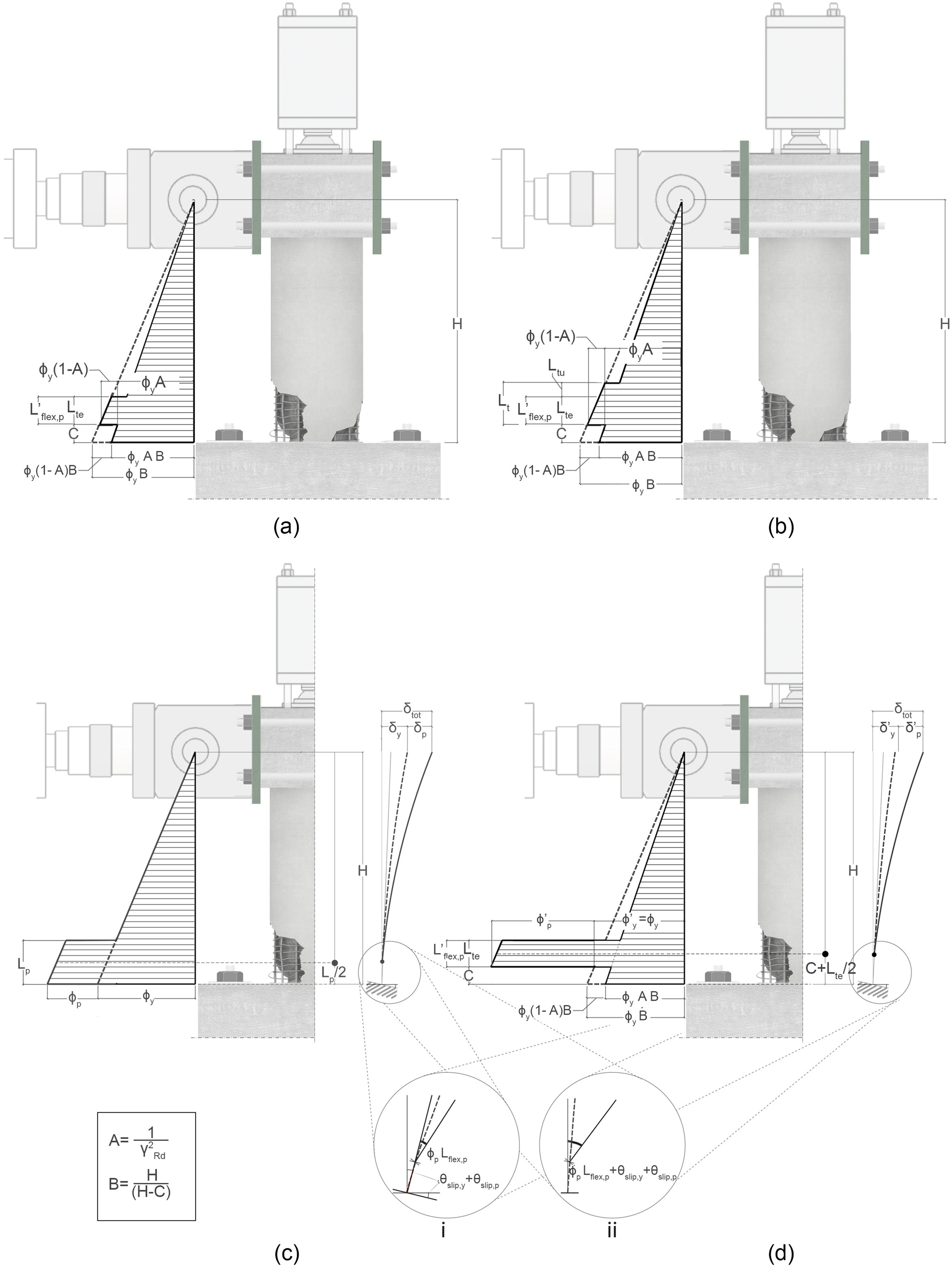
For the OR, , , , and are as follows (see Fig. 3 detail i):where = yield curvature before rehabilitation; = column height from the base to the zero-moment section; = plastic rotation due to the column internal plastic deformation before rehabilitation; = section of plastic hinge length along which there are internal plastic deformations before rehabilitation; and = plastic curvature before rehabilitation.
(8)
Therefore, the contributions for can be given, and in can be derived:
(9)
The for a circular column (Priestley 1997), as suggested in the code (CEN 2004), is as follows:where = yield strain of the rebar; and = column diameter.
(10)
is as follows (Sezen and Setzler 2008):where = rebar slip at yielding, for a concrete-steel bond stress of ; = concrete cylinder compressive strength (MPa); () = anchorage length at yielding, ; and the term () is approximated to , where = height of the compressed part of the cross section.
(11)
with a similar formulation is as follows:where = additional rebar slip to when the actual strain of the original rebar ; = stress of the original rebar (MPa) at ; and () = increment of the rebar anchorage length with respect to when , . Note that along , a residual concrete-steel bond stress of the maximum available stress () is assumed.
(12)
From Eqs. (9)–(12), can be obtained:where ; = section curvature ductility for the OR; = coefficient to obtain the section curvature ductility from the rebar ductility [see Eqs. (26) and (27)]; is the strain hardening of the original rebar; = elastic modulus of the original rebar after yielding (MPa); = elastic modulus of the original rebar (MPa); and [see Eq. (14)].
(13)
The general presentation above is suitable for treatment before and after rehabilitation (see Fig. 3 detail i). Indeed, for the OR, as an alternative to the general model presented, various (sometimes simpler) empirical models based on different expressions of the plastic hinge length () have been proposed by different researchers (Bae and Bayrak 2008; Berry et al. 2008; Feng et al. 2021; Lu et al. 2005; Ning and Li 2016; Panagiotakos and Fardis 2001; Paulay and Priestley 1992; Priestley and Park 1987). The empirical model of [Eq. (14)] (Paulay and Priestley 1992) suggested in the code (MOT 2008) is as follows (see Fig. 3 detail ii):where is the part of the plastic hinge along which the longitudinal rebars can plasticize within the column; = increment of the plastic hinge length to account, in a simplified way, for the contribution to the column top displacement associated with the rebar slip in the foundation, including both elastic and plastic slips. Therefore, instead of Eq. (9), can be expressed as follows:
(14)
(15)
Comparing Eq. (9) with Eq. (15), it can be found that in the latter equation coincides with in the former equation, and the term ) in the latter equation coincides with the contributions of the three terms (, , ) given by Eq. (8):
(16)
According to Eq. (16), the simplified Eq. (15) loses part of the clear physical representation, concentrating the effects in a single plastic hinge of length whose midpoint is at a distance () from the top of the column. To reproduce the results of the more general model of Eq. (9), should depend on the ductility demand. In fact, the expression of the contribution to the hinge length, i.e., , is valid in the case of large ductility demands for typical column geometries.
Given , the evaluation through the inversion of Eq. (13) requires an iterative procedure, whereas for large plastic displacements, the use of Eq. (15) is very simple and straightforward, and the use of Eq. (10) leads to curvature ductility. The adopted simplification is useful for the design procedure:
(17)
After rehabilitation, i.e., in the RR, only the flexural part of the plastic hinge within the column, above the connection, i.e., , can be found (Fig. 3), as the slip in the foundation is due to the anchorage, which remains in the elastic range (). It can be assumed that rebar anchorages cannot yield because of the machining of rebars.
The maximum possible length of the substituted segment that yields is along the machined part included in (see Fig. 1). The part of the machined rebar that eventually extends beyond the top of will remain elastic and is called the useless machined length (); therefore, we have the following:
(18)
To evaluate , a vertical cantilever in Fig. 3 with a horizontal force applied on the top is considered. The curvature distributions at yielding are shown in Figs. 3(a and b). The plastic range ( in the OR and in the RR), which is within the before and after rehabilitation, is shown in Figs. 3(c and d) detail i.
For the RR, at yielding () is, with a small approximation, as follows:where = yield of the rehabilitated column due to the column internal deformations; and = yield of the rehabilitated column due to the slip into the foundation of the column, contributed from the rotation () at the base, due to the strain penetration [from Eq. (11)] at yielding, as follows:
(19)
(20)
For the RR, , which is analogous to Eq. (7) of the OR, is as follows:where beyond yielding of the rehabilitated column; and = plastic of the rehabilitated column due to the column internal deformations.
(21)
The proper design of the machined rebar must take into account the increase of the section plastic demand with respect to the RR for effect of the imposed plastic strain along the machined rebar part only, i.e., , while is null; as for adequate diameter reduction, hardening of the machined part cannot induce yielding of the foundation, and the anchorages remain elastic.
The designer can adopt a reduced with respect to the maximum effective value of 0.08 · (). However, this reduction is limited by the available section curvature ductility after rehabilitation (). The prediction of can be obtained by comparing the responses of the OR and RR columns.
It can be assumed that under earthquake action, . Therefore, from Eqs. (9) and (21), Eq. (22) can be obtained:
(22)
The plastic and elastic contributions are rearranged as follows:
(23)
From Eq. (23), can be calculated as a function of with the following assumptions: , rounding to 1 some ratiosand :
(24)
Usually, ; however, it can be assumed that :
(25)
Eq. (25) can be further simplified by expressing as a function of (elastoplastic model with hardening), as follows:where is the ductility of the rebar calculated for .
(26)
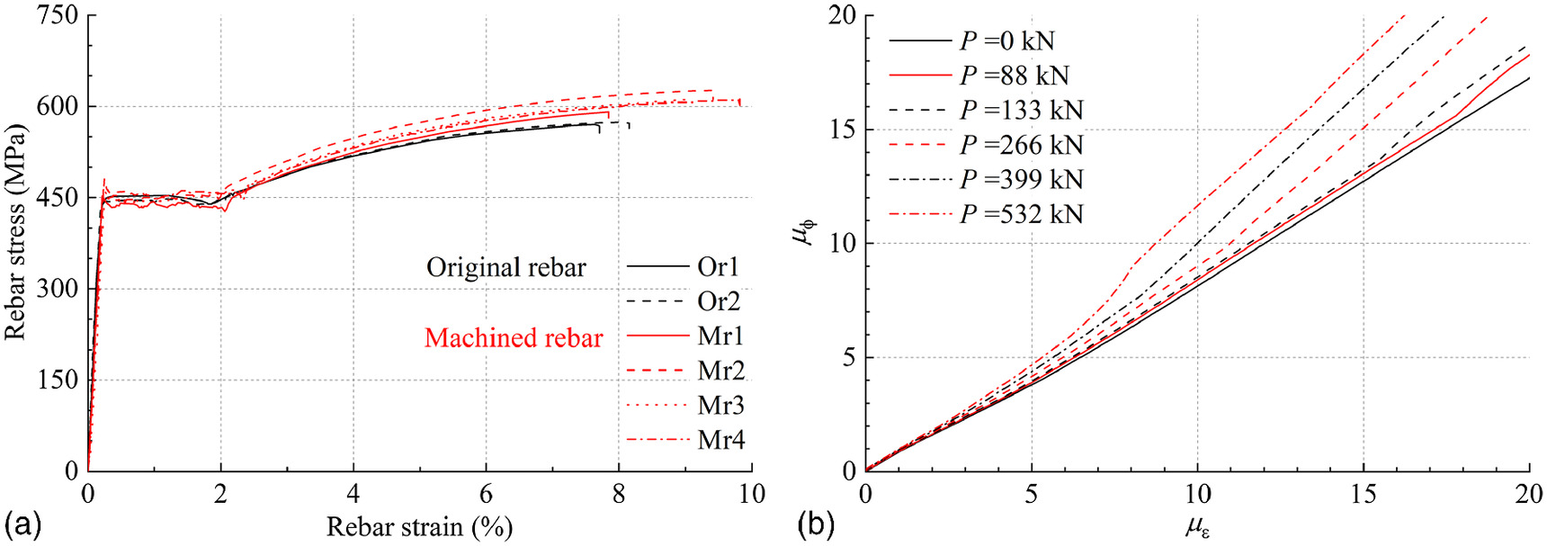
It can be assumed that the ductility of the rebar calculated for the strain , [], is as follows:where depends on the vertical axial load and, for a circular column, varies from 0.8 (in flexure) to 1.2 (for high axial loads) [see Fig. 7(a) and (b)].
(27)
Note that the first term, , depends on the elastic flexural displacement at yielding of the RR column obtained from that of the OR through the term (); the second term, , depends on the slip at yielding of the RR and OR; the third term, , depends on the flexural plastic demand of the OR; and the fourth term , depends on the slip after yielding of the RR. In addition, all four terms depend on the reduction of flexural plastic hinge length in the RR with respect to the OR, as they are divided by .
In Eq. (29), the first term is usually small and hardly overtakes 1; the second term is even smaller than half of the first term; the part depending on () in the fourth term can be neglected for large ductility (). Therefore, Eq. (29) can be simplified for large ductility demands (), including a coefficient of 1.3, as follows:
(30)
As pointed out earlier, the ductility demand in the RR depends on and . The latter expression accounts for the fact that the RR column has no contribution from the plastic slip of the OR column.
If decreases, the ductility demand increases as expected. An increase in the ductility demand is inevitable after rehabilitation, as all the demand is concentrated in the column, whereas in the OR column, part of the demand extends into the foundation. It can be observed that the plastic demand concentration in the column above the foundation guarantees the resilience of the RR column where all the plastic zones are visible. The comparisons among the experimental results and estimations based on “accurate” [Eq. (29)] or “simplified” [Eq. (30)] ductility demand expressions are provided next.
The relation among , , and the possible limitations for () can be found through enacting the following procedures. Given the increase in and the ductility of the machined rebar () with respect to the corresponding parameters of the OR columns, according to Eqs. (29) and (30) or Eq. (17), the adopted diameter reduction can be derived, which is sufficient to ensure that the total force transmitted by the new rebar segment excludes yielding in the connections (having a larger area of the connected rebars) or in the original rebars.where is the stress of the machined rebar (MPa) for the strain at maximum (); is the plastic strain of the machined rebar; is the yield strain of the machined rebar; is the strain hardening of the machined rebar; = elastic modulus of the machined rebar after yielding (MPa); and = elastic modulus of the machined rebar (MPa).
(31)
From Eq. (31), considering Eqs. (26) and (27), Eq. (32) can be obtained. It can be found that the rebar diameter of RR must be reduced on the basis of as increases.
(32)
To account for possible uncertainties in (), , and the relation between and , the capacity partial factor was used again, which is assumed to be equal to 1.2. Therefore, the reduced diameter can be obtained as follows:
(33)
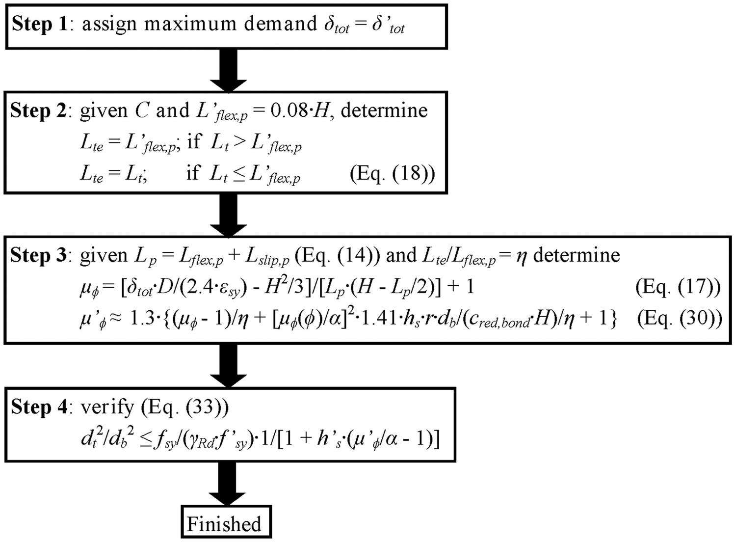
The rebar replacement procedure is summarized in Fig. 4 in the case and .
Test Program
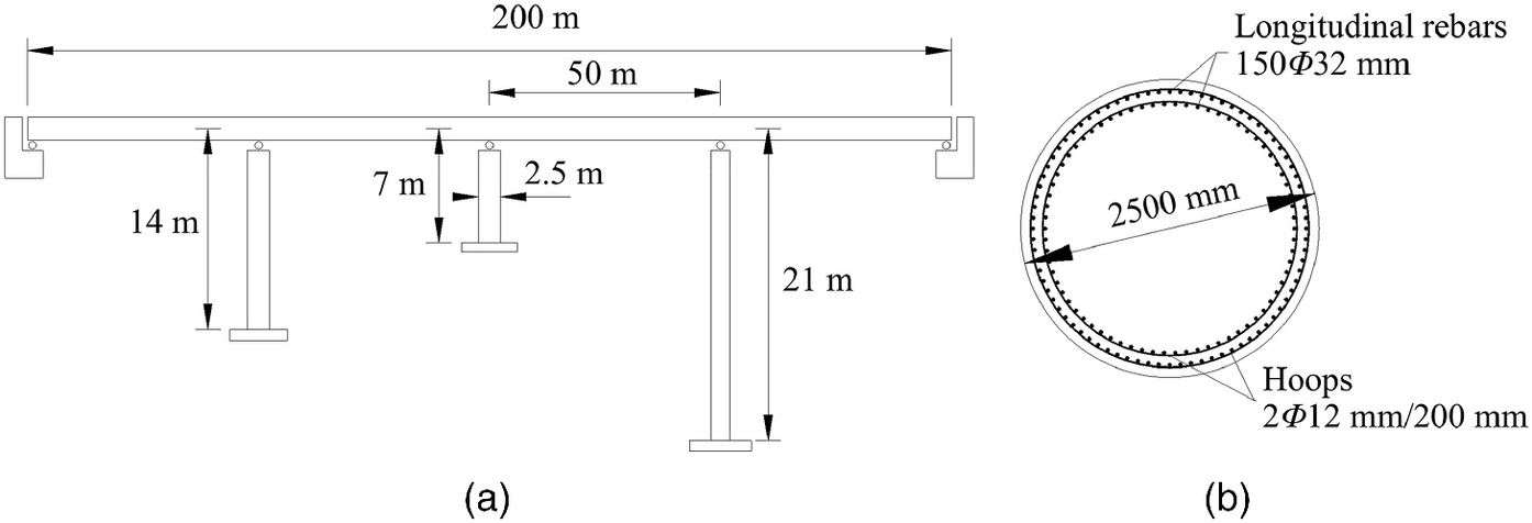
The prototype bridge (De Sortis and Nuti 1996; De Sortis et al. 1998; Lavorato 2009) for the described rehabilitation was the central RC column of the bridge in Fig. 5, which was designed according to Chinese codes (MOT 2004a, b, 2008) using a PGA of 0.35 g with a horizontal elastic spectrum reduction factor equal to 3 and a deck total vertical load of (dead and live loads for seismic design). The material characteristics for the design in the Chinese codes were as follows: (1) concrete, grade C30 (); (2) longitudinal rebar, steel type HRB335E (yield stress ); and (3) hoops, steel type Q235A (yield stress ). The hoops were not proportioned using capacity design, rather a typical volumetric hoop ratio of 0.2% was adopted.
RC Column Specimens
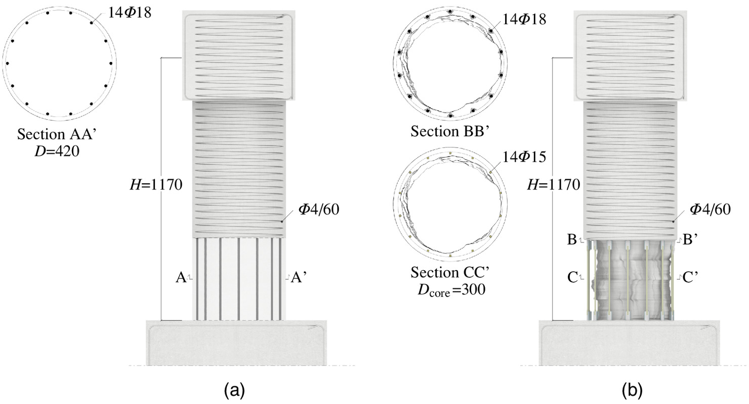
Three specimens of the central column at scale (P16A, P16B, and P16C called OR) were fabricated, with of 420 mm, of , and the same material characteristics of the prototype bridge column. The adopted steel reinforcements, 14 longitudinal rebars with values of 18 mm, and hoops with diameter and a distance of 60 mm, are illustrated in Fig. 6(a). More information can be found in Lavorato and Nuti (2015).
SCC had a mean cubic compressive strength of 31 MPa; the original HRB335E longitudinal rebars had a yield stress of 450 MPa, maximum strength , and strain hardening: () and [Fig. 7(a) and Table 1].
| Material | (MPa) | Yield stress (MPa) | Maximum stress (MPa) | or () | or |
|---|---|---|---|---|---|
| SCC | 31 | — | — | — | — |
| Original rebar () | — | 450 | 550 | ||
| Machined rebar ( and ) | — | 456 | 600 | ||
| Machined rebar ( and ) | — | 486 | 600 | ||
| Machined rebar ( and ) | — | 484 | 600 | ||
| Hoop | — | — | — | — | |
| Steel equal angle | — | — | — | — |
The ORs were damaged by imposing the sequence ( in the following) induced by an intense ground motion (Lavorato and Nuti 2015) and then rehabilitated by means of the procedure described above. The same imposed values were used for the tests after rehabilitation. The three rehabilitated specimens (R26-250-15, R36-125-15, and R46-240-14 called RR), which are shown in Fig. 6(b), have new longitudinal rebar segments realized from the same rebars of the OR. The new rebar segments were machined to obtain the reduced diameters: or 14 mm for different values: 250, 125, or 240 mm, as reported in Table 2. The machined and original rebars have similar characteristics with strain hardening: () and [Fig. 7(a) and Table 1]. The diameter of the column core after concrete removal () is approximately 300 mm.
The welding length of the connector to the original rebar was 36 mm () for each side of the rebar. The connector length was and [see Figs. 1(b and c)]. The connector had a larger than 400 MPa and an of .
The machined rebar geometries of R26-250-15 were calculated step by step following Fig. 4. The following data were provided: , , , MPa, () and , and () and .
The starting point (step 1) is the maximum (seismic response imposed during the test) and , a choice that satisfies Eq. (6). In step 2, given , · , is obtained from Eq. (18). In step 3, given [Eq. (14)], can be determined by Eq. (17) and can be determined by Eq. (30).
Priestley’s formula, Eq. (14), has been calibrated and holds true for the typical geometries of bridge columns. It should be used with some consciousness regarding the specimens, which are scaled . This way, the plastic hinge length in the foundation is overestimated by approximately 2 times, as will be observed in the experimental results. In this paper, ; therefore, . is assumed to be 0.8.
The ductility passes from [Eq. (17)] for the OR to [Eq. (30)] for all RRs at . If the accurate expression [Eq. (29)] was used, the following differences can be found: for R26-250-15 and R36-125-15, and for R46-240-14. In step 4, Eq. (33) gives or (Table 2). The shown in Table 2 guarantees that yielding develops within the machined part of the new rebar segment according to the design procedure.
The hoop replacement in the rehabilitation zone, determined on the basis of the capacity design from OR demand and RR capacity (MOT 2008; similar to CNR 2013 and FIB 2001), included hoops of () and additional external unidirectional CFRP wrapping. The required number of CFRP layers for each reinforcement ring is equal to 2.5 according the formulations in the Chinese code (CECS 2003) (2.3 for CNR 2013), assuming a ring width of 80 mm, commercial tissue thickness of 0.167 mm, ring spacing of 120 mm, elastic modulus of the CFRP equal to MPa, and CFRP maximum allowable strain of 0.005. To guarantee shear strength in the presence of possible irregularities in the application on site, discontinuous rings with three layers of CFRP per ring, instead of 2.5, was chosen in the research. The CFRP layers used in the rehabilitation of real bridge columns should be calculated according to the code (CECS 2003; CNR 2013).
The damaged concrete in RR was restored by means of SCC with the same characteristics used in OR. SCC and CFRP wrapping are materials with well-known behaviors; therefore, the experimental tests reported in this paper mainly focused on the effects of the different geometries of the new rebar segments. The vertical load was not applied during the rehabilitation operations, as reported previously in the description of the rehabilitation procedure. This feature does not seem to reduce the representativity of cases in which the vertical load is not eliminated during rehabilitation, as discussed in the literature review.
Test Setup and Loading History
The specimens were tested at the Structural Laboratory of Fuzhou University by applying (axial force at specimen scale; the percentage of the applied axial force to the axial capacity of the column is approximately 7.5%), and the top horizontal displacement history recorded on the central -scale bridge column was obtained by pseudo dynamic testing (Lavorato and Nuti 2015), having the same geometry but with a European code–based design (CEN 2004). The first part (T) was the response to the Tolmezzo accelerogram (Italy, 1976), and the second part () was the identical but multiplied by 2 (Fig. 8). The imposed history was nonsymmetric, with values in the negative direction greater than those in the positive direction. The imposed displacement ductility of the RR was 30%–38% larger than that of the OR. The latter had a of 8.6 mm, whereas the former had a of 5.3–6.1 mm, depending on the different rehabilitation arrangements (Fig. 8).
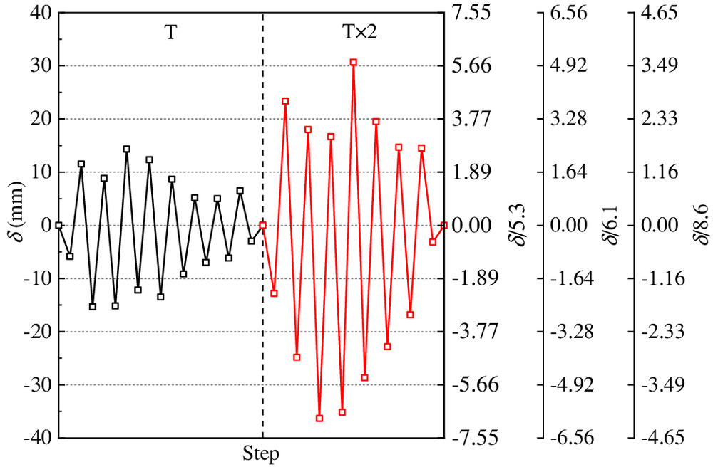
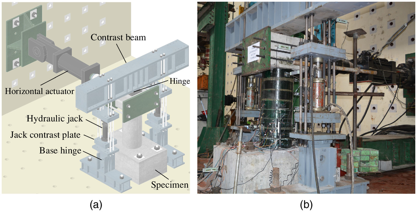
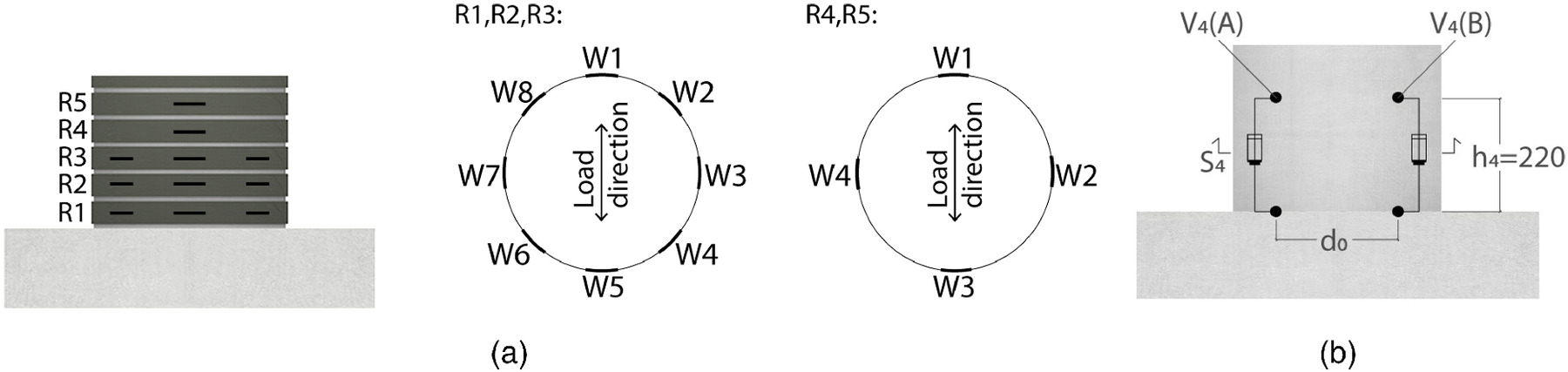
Fig. 9 shows the 3D drawing and photo of the test setup, which consisted of a steel frame pinned to the floor to apply a constant by using two 600-kN hydraulic jacks and a 500-kN MTS hydraulic actuator to impose the history on the top of the specimen. The and base shear were measured by an MTS system. was measured by load cells. The vertical elongations in the plastic hinge zone and the CFRP strains were measured by potentiometers (V) and strain gauges (W) placed on the CFRP rings, respectively, as illustrated in Fig. 10.
Experimental Results
Damage Survey
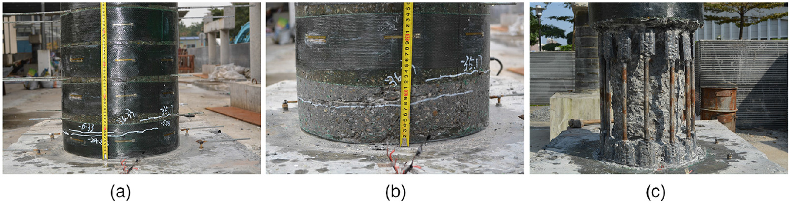
For OR, the first crack occurred at the base under the first peak of . When reached , which is the maximum negative in T, seven cracks were found. When reached 30.67 and , which are the maximum positive and negative in , respectively, the width of existing cracks increased and concrete crush was found at the base. Damage to the OR at the end of the test consisted of cover spalling, hoop yielding, and buckling of thelongitudinal rebar. For RR, the first crack appeared between the R1 and R2 CFRP rings, which is within the machined part of the new rebar segment under the first peak of . When the values reached and 14.33 mm, which are the maximum negative and positive in T, respectively, the width of the existing crack increased; however, no new crack appeared. When reached 23.33 mm in , a new crack appeared at the mid-height of the R1 CFRP ring. Damage to the RR at the end of the test consisted of horizontal flexure cracks within the zone of the machined part only [Fig. 11(a)]. There were no CFRP tissue horizontal ruptures; however, after CFRP jacket removal, modest cracks were evident at the height of the R1 and R2 CFRP rings [Fig. 11(b)]. The crack in the concrete that appeared at the RR base (for the RR column there is elastic rebar slip only that is smaller than the one of the OR column) was smaller than the one that developed at the base of the OR, confirming the validity of the design procedure for the new rebar segment. After the removal of the concrete cover [Fig. 11(c)], the connections and the new rebar segments were intact with no buckling in the rebars, as observed in previous tests on conventional rehabilitation specimens (Lavorato and Nuti 2015).
Curvature
From Eq. (34), the experimental rotation at the top of the column height at the specimen base can be evaluated from the vertical excursions of potentiometers (A) and (B) placed on the opposite sides of each specimen (Fig. 10), as follows:where = distance between the vertical transducers (Fig. 10).
(34)
The experimental plastic rotation due to the flexural contribution () can be calculated as follows:where [Eq. (11)] for the OR, whereas for R26-250-15 and R36-125-15, and for R46-240-14 [Eq. (20)]; is obtained from Eq. (12) and depends on the level of stress in the steel rebars relative to the displacement (Table 3), whereas ; and and = experimental rotations at yielding due to the flexural contribution before and after rehabilitation, which can be calculated by the curvature distributions along : for the OR; for R26-250-15 and R36-125-15; and for R46-240-14.
(35)
| Specimen | or (mm) | (rad) | () (MPa) | (rad) | (rad) | |
|---|---|---|---|---|---|---|
| P16 | 23.4 | 0.013 | 455.8 | 0.021 | 0.0004 | 0.008 |
| 30.7 | 0.020 | 490.8 | 0.029 | 0.0042 | 0.011 | |
| 0.025 | 506.0 | 0.035 | 0.0060 | 0.014 | ||
| R26-250-15 | 23.4 | 0.014 | — | — | — | 0.010 |
| 30.7 | 0.021 | — | — | — | 0.017 | |
| 0.027 | — | — | — | 0.023 | ||
| R36-125-15 | 23.4 | 0.017 | — | — | — | 0.013 |
| 30.7 | 0.023 | — | — | — | 0.019 | |
| 0.031 | — | — | — | 0.027 | ||
| R46-240-14 | 23.4 | 0.018 | — | — | — | 0.015 |
| 30.7 | 0.024 | — | — | — | 0.021 | |
| 0.031 | — | — | — | 0.027 |
The mean experimental plastic curvature along , in the plastic hinge, can be estimated from the experimental plastic rotation [Eq. (35)] by dividing the portion of where plastic deformation of the rebar develops ():
(36)
From Fig. 1, for the OR, whereas for the RR. Note that for RR, is part of the machined zones that are 250, 125, and 240 mm.
In Table 3, for three values of imposed peak displacements (), the experimental rotations at from the base are shown with the derived rebar stress and strain [(); ], the slip plastic rotation , and the flexural plastic rotation [Eq. (35)]. For the OR, the values of in the case of and [see Fig. 7(a)], and for each displacement.
In Table 4, for the same displacements, the section curvature ductility values ( or ) at are compared with those obtained by the accurate [Eq. (29)] or simplified [Eq. (30)] expressions. The values of ductility in the OR derived by Eq. (17) are given as well. It should be noted that, as expected, the latter expression has a reduced accuracy for smaller displacements.
Hysteretic Responses
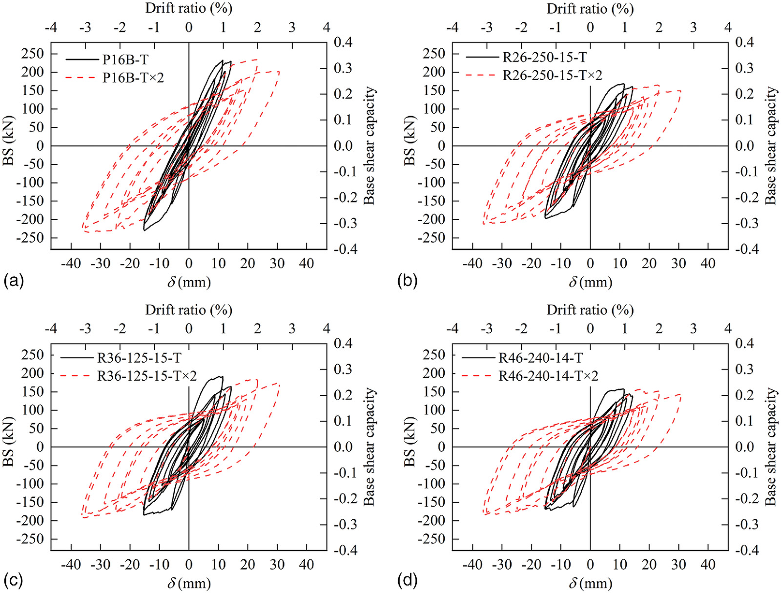
The base shear (BS) versus top horizontal displacement () of the OR and is are plotted in Fig. 12, and the corresponding base shear capacity [normalized by dividing into BS] and drift ratio (normalized by dividing into ) are also represented.
The hysteretic responses of the specimens are compared with reference to the positive direction in Table 5 for . In Table 5, the larger ductility demands and steel stress values of the RR specimens are evident, whereas the reduction in BS confirms that the original rebars and relative connections remain in the elastic field. The ratio between and is strongly related to the ratio between the BS values. Although the section is circular, the relation is not immediate.
It can also be found that in the OR, there was a significant reduction in BS for a large ductility demand [Fig. 12(a)], whereas in the RR, there was a more stable BS [Figs. 12(b–d)]. The shapes of the hysteretic cycles for the RR were wider than those for the OR, confirming the good plastic behavior of the machined part of the new rebar segments. The RR specimens are confined by the CFRP jacket. This latter was also used in the test of Lavorato and Nuti (2015), and the cycles after rehabilitation were not as satisfying as those here; in fact, the replacement segments had old-style connections and no diameter reduction. The BS of RR (base shear capacity from 0.23 to 0.3) was, as expected, smaller than that of OR (base shear capacity of 0.33) owing to rebar area reduction. The results confirmed that the proposed procedure (Table 5) guaranteed that the connection to the original rebar remained elastic.
The theoretical evaluation of varied between 5.34 and 6.13 mm for the RR and was 8.63 mm for the OR, which is in line with the test results (see Fig. 12). Therefore, the requested displacement ductility demand was approximately for the OR and ranged from to for the RR in the positive direction. The ductility demands were approximately larger for RR than for OR. Failure displacement, which is usually assumed to correspond to the loss of the maximum BS of 20%, was not reached in any of the OR and RR specimens. The OR showed a decrease in BS at large cyclic displacements in . The RR did not show the same BS decrease phenomenon; therefore, the failure displacement of the RR could be speculated to be greater than that of the OR. The stability in the cycles validated the rehabilitation design procedure and the proposed value of in the case at hand.
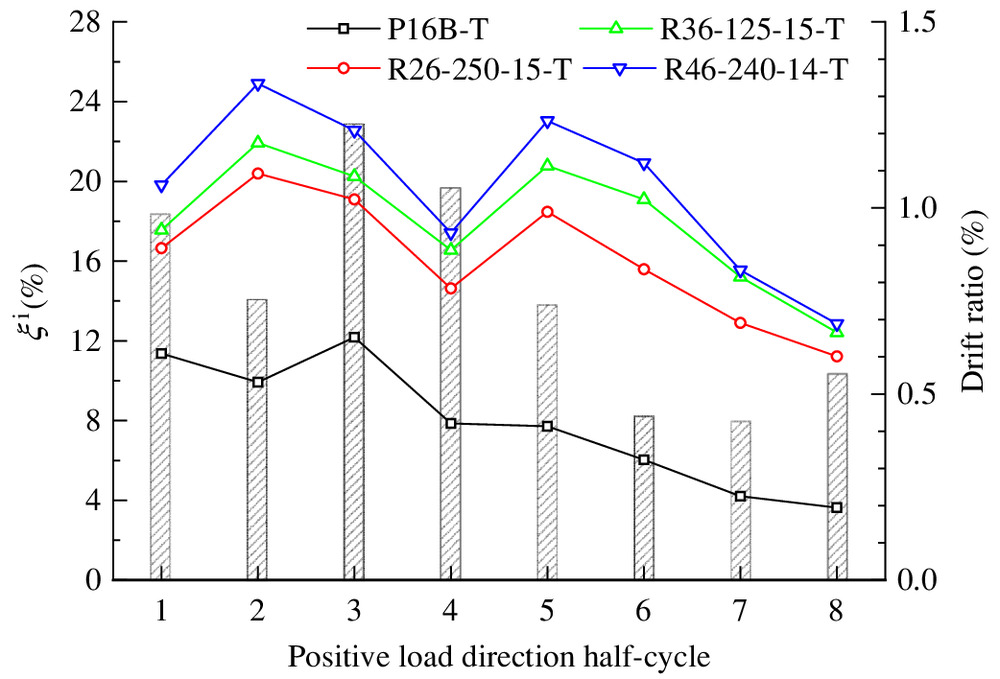
Equivalent Viscous Damping Ratio
The equivalent viscous damping ratio () can be evaluated by Eq. (37) considering the positive half-cycle of the BS versus the curves, as follows:where and are the maximum and BS for each th half cycle, respectively; and is the dissipated energy for each th half cycle (assuming one half of the energy dissipated in a symmetric cycle). The values for the cycles (lines with symbols) with the corresponding drift ratios (vertical columns) are given in Fig. 13. Compared with the of the OR, the of the RR increased significantly from 50% to 250%. The mean values during the first five cycles (low cycle fatigue excitation) were 9.8% for P16B, 17.8% for R26-250-15, 19.4% for R36-125-15, and 21.9% for R46-240-14.
(37)
CFRP Circumferential Strains
CFRP jacketing was used for only the RR, not for the OR. The maximum CFRP circumferential strains in different rings measured by strain gauges (see Fig. 10 for positions) in the negative direction (pull) and or in the positive direction (push) versus the CFRP height ratio (normalized by dividing into CFRP height) of the OR and RR are plotted in Fig. 14.
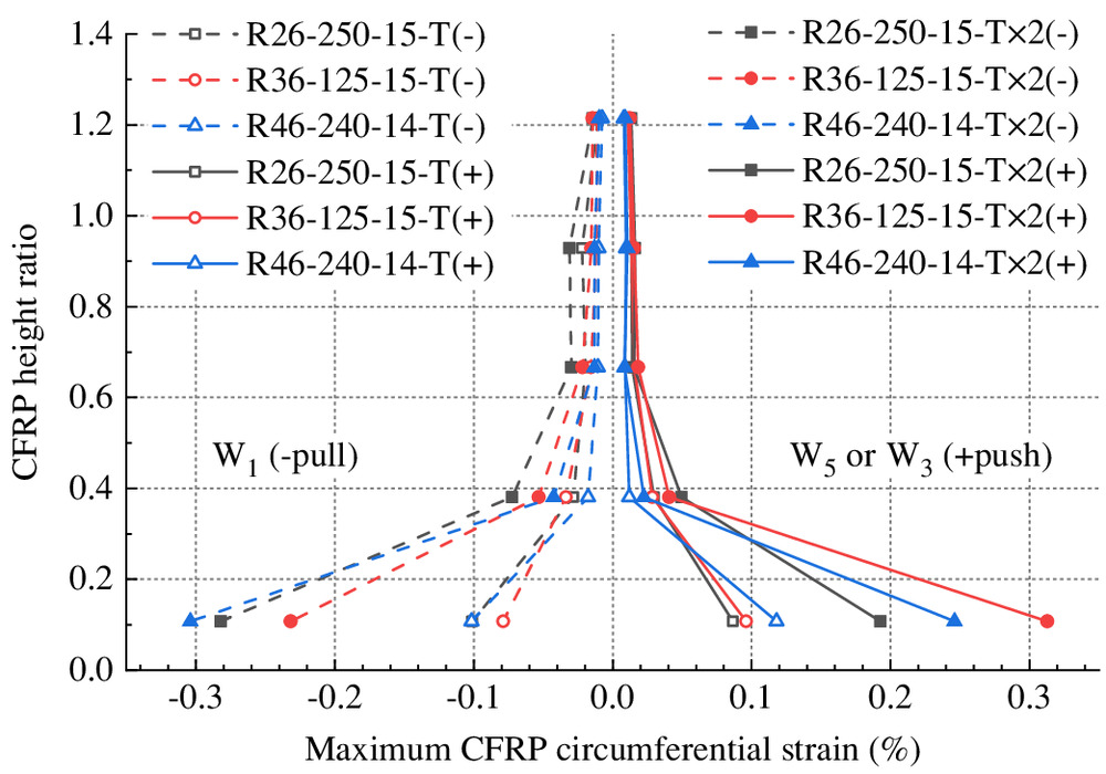
The specimens showed very similar distributions for the mean CFRP strains at different heights in the positive and negative directions. At the base (ring ), the strains were approximately 0.001 for T and varied between 0.002 and 0.003 for . The upper four measures were smaller: in ring , the strains were approximately 0.0005 for , while the strains became very small in the upper three rings (, , and ). Moreover, at the base, R46-240-14 had the largest strains except for in the positive direction for R36-125-15. In any case, the maximum strains were always smaller than those indicated in the codes (0.004–0.005) to design the shear reinforcement (CECS 2003; CNR 2013; FIB 2001).
The plastic hinges were expected to be concentrated in areas where strains in the rings were larger, although it should be noted that the plastic behavior essentially depends on steel under tension and not on concrete under compression. It can be concluded that the plastic hinges were concentrated in the lower parts of the specimens without significant differences between the three solutions adopted.
Summary and Conclusions
A technique for rehabilitating RC bridge columns with severely damaged/fractured longitudinal rebars has been proposed and validated experimentally on three -scale circular column specimens. Commercial new rebar segments with central zones with reduced diameters obtained by machining and using steel equal angles as connectors are used to replace the damaged/fractured longitudinal rebars, and the plastic hinge is included in only the new rebar segment. The diameter and length of the machined part were obtained through a capacity design procedure. Only the cover and damaged concrete column parts are removed, foundation rehabilitation is not necessary, and strong provisional structures are not used because rebar replacement does not require column core removal. The ends of the new rebar segment and the original rebar that remain in the column after removing the damaged zone do not require special preparation to execute the connector. The short connector, which is obtained by cutting an off-the-shelf steel equal angle, also permits welding in the case of imperfect alignment of the damaged rebars. On the other hand, the geometry of the connector allows the removal of only a small depth of concrete in addition to the cover. The following main conclusions can be drawn based on the experimental and theoretical investigation and within the limited cases examined:
•
the rehabilitated columns exhibited very stable behavior with large ductility capacity values (39%–58% increase with respect to the original column) and very little damage (no rebar buckling, no crushing of the concrete, few cracks);
•
after rehabilitation, the columns had substantially increased energy dissipation (a damping increase from 50% to 250% with respect to the original column);
•
plasticization was limited to the machined zone of the rebar, avoiding possible crisis and damage to the connection and in the foundation;
•
the theory developed was validated based on the test results and allowed the dimensions (diameter and length of the machined part) of the replaced rebar segment to be determined, with good forecasting of the new local ductility demands;
•
the short connector had an important role of not allowing the plastic hinge to be dislocated, and it did not reduce the concrete cover; and
•
the maximum loads on the foundation were reduced (owing to rebar diameter reduction), eliminating the need for its rehabilitation.
More research is still needed to investigate cases in which the bending strength should be increased after rehabilitation, the effect of a large vertical load during rehabilitation, the effect of the scale testing of large-scale specimens, the possible increase of service life with repair/rehabilitation, the calibration of capacity coefficients to better account for uncertainties in the existing rebar characteristics, and the possible shear demand increase in adjacent columns.
Notation
The following symbols are used in this paper:
- cross-section area of connector;
- cross-section area of column;
- ratio of the base shears for the rehabilitated and original columns;
- total length between the column bottom end and the machined start position;
- total length of the connector;
- gap needed for butt-welding;
- gap between the connector end and the machined start position;
- residual concrete–steel bond stress;
- column diameter;
- diameter of the column core after concrete removal;
- maximum displacement for each th half cycle;
- diameter of the original rebar;
- diameter of the machined rebar;
- distance between vertical transducers;
- elastic modulus of the original rebar;
- elastic modulus of the machined rebar;
- dissipated energy for each th half cycle;
- elastic modulus of the original rebar after yielding;
- elastic modulus of the machined rebar after yielding;
- maximum force for each th half cycle;
- force in the rebar before rehabilitation;
- force in the rebar after rehabilitation;
- mean rebar stress before rehabilitation;
- mean rebar stress after rehabilitation;
- tensile strength of the original rebar;
- yield stress of the hoop;
- yield stress of the original rebar;
- yield stress of the steel equal angle;
- stress of the original rebar at which is larger than ;
- concrete cylinder compressive strength;
- yield stress of the new rebar segment;
- stress of the machined rebar for strain ;
- column height from the base to the zero-moment section;
- strain hardening of the original rebar;
- strain hardening of the machined rebar;
- column height where the potentiometer V4 is installed;
- additional gap length;
- length of the removed concrete part;
- part of plastic hinge length along which there are the internal plastic deformations in the section before rehabilitation;
- total length of the new rebar segment having no diameter reduction;
- plastic hinge length before rehabilitation;
- portion of where plastic deformation of rebar develops;
- increment of the plastic hinge length to account the contribution to the column top displacement associated to the rebar slip in the foundation, including both elastic and plastic slips;
- machined length of the new rebar segment;
- adopted ;
- effective machined length of the new rebar segment;
- total length of the new rebar segment;
- useless machined length that eventually extends beyond the top of and will remain elastic;
- part of plastic hinge length along which there are the internal plastic deformations in the section after rehabilitation;
- plastic hinge length after rehabilitation;
- increment of the rebar anchorage length with respect to when ;
- anchorage length at yielding;
- mean compressive strength of the concrete cubes;
- ratio of the yield stress of the original rebar () and the square root of the concrete cylinder compressive strength ();
- additional rebar slip to when the actual steel strain is larger than yield strain;
- rebar slip at yielding;
- height of the compressed part of the cross section;
- coefficient to obtain section curvature ductility from rebar ductility;
- coefficient to consider the uncertainties regarding the original and new steel material characteristics and the hardening of the new rebar segment after yielding;
- top horizontal displacement of the column;
- plastic of the original column due to the column internal deformations;
- yield of the original column due to the column internal deformations;
- beyond yielding of the original column;
- plastic of the original column due to the slip into the foundation of the column;
- yield of the original column due to the slip into the foundation of the column;
- total of the original column;
- yield of the original column;
- plastic of the rehabilitated column due to the column internal deformations;
- yield of the rehabilitated column due to the column internal deformations;
- beyond yielding of the rehabilitated column;
- plastic of the rehabilitated column due to the slip into the foundation of the column;
- yield of the rehabilitated column due to the slip into the foundation of the column;
- total of the rehabilitated column;
- yield of the rehabilitated column;
- actual strain of the original rebar;
- yield strain of the original rebar;
- strain of the machined rebar at maximum ;
- plastic strain of the machined rebar;
- yield strain of the machined rebar;
- ratio of effective machined length of the new rebar segment () and column length with internal deformations before rehabilitation ();
- plastic rotation due to the column internal plastic deformation before rehabilitation;
- concentrated rotations at the base beyond yielding before rehabilitation;
- concentrated rotations at the base at yielding before rehabilitation;
- concentrated rotations at the base beyond yielding after rehabilitation;
- concentrated rotations at the base at yielding after rehabilitation;
- experimental rotation at the top of the column height on which potentiometer is installed;
- experimental plastic rotation due to the flexural contribution before rehabilitation;
- experimental rotation at yielding due to the flexural contribution before rehabilitation;
- experimental rotation at yielding due to the flexural contribution after rehabilitation;
- ductility of the rebar calculated for actual strain which is larger than ;
- section curvature ductility for the original column;
- section curvature ductility at of the original column;
- ductility of the machined rebar;
- section curvature ductility for the rehabilitated column;
- section curvature ductility at of the rehabilitated column;
- equivalent viscous damping ratio at the th half cycle;
- plastic curvature before rehabilitation;
- yield curvature before rehabilitation;
- plastic curvature after rehabilitation;
- mean experimental plastic curvature along ;
- adopted (); and
- maximum design ().
Data Availability Statement
All data, models, and code generated or used during the study appear in the published article.
Acknowledgments
This research was supported by the National Natural Science Foundation of China (Grant Nos. 51778148 and 51508103), the Open Project of Fujian Provincial Key Laboratory on Multi-Disasters Prevention and Mitigation in Civil Engineering (MPMC-2022-4), the Laboratories University Network of Seismic Engineering (ReLUIS) research projects DPC/ReLUIS 2019-2021 and 2022-2024 UR RM3 WP 11.2-11.3, and Federbeton (Italy) “Seismic Behavior of Integral Bridges.” The authors also acknowledge the Sustainable and Innovative Bridge Engineering Research Center (SIBERC) of the College of Civil Engineering, Fuzhou University, and the PRISMA lab of the Dept. of Architecture at Roma Tre University (Rome). The authors acknowledge the work of C. Contiguglia for important contributions to the figures and schemes. Financial support from the Italian Ministry of Education, University and Research (MIUR) in the framework of the Project FISR 2019: “Eco Earth” (code 00245) is gratefully acknowledge.
References
Albanesi, T., D. Lavorato, C. Nuti, and S. Santini. 2009. “Experimental program for pseudodynamic tests on repaired and retrofitted bridge piers.” Eur. J. Environ. Civ. Eng. 13 (6): 671–683. https://doi.org/10.1080/19648189.2009.9693145.
ATC (Applied Technology Council). 1997. Seismic design criteria for bridges and other highway structures: Current and future. ATC-18. Redwood City, CA: ATC.
AWS (American Welding Society). 2011. Structural welding code–reinforcing steel. AWS D1.4/D1.4M. Miami: AWS.
Bae, S., and O. Bayrak. 2008. “Plastic hinge length of reinforced concrete columns.” ACI Struct. J. 105 (3): 290–300. https://doi.org/10.14359/19788.
Berry, M. P., D. E. Lehman, and L. N. Lowes. 2008. “Lumped-plasticity models for performance simulation of bridge columns.” ACI Struct. J. 105 (3): 270–279. https://doi.org/10.14359/56427.
Bett, B. J., R. E. Klingner, and J. O. Jirsa. 1988. “Lateral load response of strengthened and repaired reinforced concrete columns.” ACI Struct. J. 85 (5): 499–508. https://doi.org/10.14359/9226.
Briseghella, B., C. Demartino, A. Fiore, C. Nuti, C. Sulpizio, I. Vanzi, D. Lavorato, and G. Fiorentino. 2019. “Preliminary data and field observations of the 21st August 2017 Ischia earthquake.” Bull. Earthqake Eng. 17 (3): 1221–1256. https://doi.org/10.1007/s10518-018-0490-x.
CECS (China Association for Engineering Construction Standardization). 2003. Technical specification for strengthening concrete structures with carbon fiber reinforcea polymer laminate. [In Chinese.] CECS 146:2003. Beijing: CECS.
CEN (European Committee for Standardization). 2004. Design of structures for earthquake resistance. Eurocode 8. Brussels, Belgium: CEN.
CEN (European Committee for Standardization). 2020. Assessment and retrofitting of existing structures. CEN/TS 17440. Brussels, Belgium: CEN.
Chai, Y. H., M. J. N. Priestley, and F. Seible. 1991. “Seismic retrofit of circular bridge columns for enhanced flexural performance.” ACI Struct. J. 88 (5): 572–584. https://doi.org/10.14359/2759.
Chang, S.-Y., Y.-F. Li, and C.-H. Loh. 2004. “Experimental study of seismic behaviors of as-built and carbon fiber reinforced plastics repaired reinforced concrete bridge columns.” J. Bridge Eng. 9 (4): 391–402. https://doi.org/10.1061/(ASCE)1084-0702(2004)9:4(391).
Chellapandian, M., and S. S. Prakash. 2018. “Rapid repair of severely damaged reinforced concrete columns under combined axial compression and flexure: An experimental study.” Constr. Build. Mater. 173 (Jun): 368–380. https://doi.org/10.1016/j.conbuildmat.2018.04.037.
Cheng, C. T., and J. B. Mander. 1997. Seismic design of bridge columns based on control and repairability of damage. Buffalo, NY: State Univ. of New York at Buffalo.
Cheng, C.-T., J.-C. Yang, Y.-K. Yeh, and S.-E. Chen. 2003. “Seismic performance of repaired hollow-bridge piers.” Constr. Build. Mater. 17 (5): 339–351. https://doi.org/10.1016/S0950-0618(02)00119-8.
Cheng, C.-T., Y.-K. Yeh, and Y.-L. Mo. 2004. “Flexural repair of hollow rectangular bridge columns failed due to earthquake-type loading.” Mater. Struct. 37 (10): 717–723. https://doi.org/10.1007/BF02480517.
CNR (National Research Council). 2013. Guide for the design and construction of externally bonded FRP systems for strengthening existing structures. CNR-DT 200 R1/2013. Rome: CNR.
De Sortis, A., and C. Nuti. 1996. “Seismic response by pseudodynamic tests of RC bridges designed to EC8.” In Proc., 11th World Conf. on Earthquake Engineering, 1310. Amsterdam, Netherlands: Elsevier.
De Sortis, A., C. Nuti, and M. Petrangeli. 1998. “Seismic response by pseudodynamic tests of RC bridges designed to Eurocode 8 and Italian seismic code.” In Proc., 11th European Conf. on Earthquake Engineering, 1–16. Rotterdam, Netherlands: A.A. Balkema.
Elsouri, A. M., and M. H. Harajli. 2011. “Seismic repair and strengthening of lap splices in RC columns: Carbon fiber–reinforced polymer versus steel confinement.” J. Compos. Constr. 15 (5): 721–731. https://doi.org/10.1061/(ASCE)CC.1943-5614.0000213.
Feng, D.-C., B. Cetiner, M. R. A. Kakavand, and E. Taciroglu. 2021. “Data-driven approach to predict the plastic hinge length of reinforced concrete columns and its application.” J. Struct. Eng. 147 (2): 04020332. https://doi.org/10.1061/(ASCE)ST.1943-541X.0002852.
Ferrotto, M. F., O. Fischer, and L. Cavaleri. 2018a. “Analysis-oriented stress–strain model of CRFP-confined circular concrete columns with applied preload.” Mater. Struct. 51 (2): 44. https://doi.org/10.1617/s11527-018-1169-0.
Ferrotto, M. F., O. Fischer, and L. Cavaleri. 2018b. “A strategy for the finite element modeling of FRP-confined concrete columns subjected to preload.” Eng. Struct. 173 (Oct): 1054–1067. https://doi.org/10.1016/j.engstruct.2018.07.047.
Ferrotto, M. F., O. Fischer, and R. Niedermeier. 2018c. “Experimental investigation on the compressive behavior of short term preloaded CFRP-confined concrete columns.” Struct. Concr. 19 (4): 988–1001. https://doi.org/10.1002/suco.201700072.
FIB (International Federation for Structural Concrete). 2001. Externally bonded FRP reinforcement for RC structures. FIB Bulletin, N 14. Lausanne, Switzerland: FIB.
Forte, A., S. Santini, G. Fiorentino, D. Lavorato, A. V. Bergami, and C. Nuti. 2018. “Influence of materials knowledge level on the assessment of the shear strength characteristic value of existing RC beams.” In Proc. of the 12th FIB Int. PhD Symp. in Civil Engineering, 1–8. Prague, Czechia: Czech Technical Univ. in Prague.
French, C. W., G. A. Thorp, and W. J. Tsai. 1990. “Epoxy repair techniques for moderate earthquake damage.” ACI Struct. J. 87 (4): 416–424. https://doi.org/10.14359/2758.
He, R., S. Grelle, L. H. Sneed, and A. Belarbi. 2013a. “Rapid repair of a severely damaged RC column having fractured bars using externally bonded CFRP.” Compos. Struct. 101 (Jul): 225–242. https://doi.org/10.1016/j.compstruct.2013.02.012.
He, R., L. H. Sneed, and A. Belarbi. 2013b. “Rapid repair of severely damaged RC columns with different damage conditions: An experimental study.” Int. J. Concr. Struct. Mater. 7 (1): 35–50. https://doi.org/10.1007/s40069-013-0030-7.
He, R., L. H. Sneed, and A. Belarbi. 2014. “Torsional repair of severely damaged column using carbon fiber-reinforced polymer.” ACI Struct. J. 111 (3): 705–716. https://doi.org/10.14359/51686627.
He, R., Y. Yang, and L. H. Sneed. 2015. “Seismic repair of reinforced concrete bridge columns: Review of research findings.” J. Bridge Eng. 20 (12): 04015015. https://doi.org/10.1061/(ASCE)BE.1943-5592.0000760.
He, R., Y. Yang, and L. H. Sneed. 2016. “Post-repair seismic assessment of RC bridges damaged with fractured column bars—A numerical approach.” Eng. Struct. 112 (Apr): 100–113. https://doi.org/10.1016/j.engstruct.2016.01.007.
Hwang, S.-H., K.-H. Yang, Y.-S. Choi, and S.-J. Kwon. 2021. “Axial and flexural performances of columns restored after severe damage.” J. Build. Eng. 44 (Dec): 102686. https://doi.org/10.1016/j.jobe.2021.102686.
Kheyroddin, A., S. Rouhi, and H. Dabiri. 2021. “An experimental study on the influence of incorporating lap or forging (GPW) splices on the cyclic performance of RC columns.” Eng. Struct. 241 (Aug): 112434. https://doi.org/10.1016/j.engstruct.2021.112434.
Kunwar, B., V. McEntee, and C. P. Pantelides. 2021. “Seismic repair of deficient and code compliant bridge wall piers.” Eng. Struct. 233 (Apr): 111595. https://doi.org/10.1016/j.engstruct.2020.111595.
Lavorato, D. 2009. Pseudo-dynamic tests on reinforced concrete bridge piers repaired and/or retrofitted by means of techniques based on innovative materials. Roma: Università degli studi ROMA TRE.
Lavorato, D., A. V. Bergami, C. Nuti, B. Briseghella, J. Q. Xue, A. M. Tarantino, G. C. Marano, and S. Santini. 2017. “Ultra-high-performance fibre-reinforced concrete jacket for the repair and the seismic retrofitting of Italian and Chinese RC bridges.” In Proc., COMPDYN—Proc. Int. Conf. on Computational Methods in Structural Dynamics and Earthquake Engineering, 2149–2160. Athens, Greece: National Technical Univ. of Athens.
Lavorato, D., and C. Nuti. 2015. “Pseudo-dynamic tests on reinforced concrete bridges repaired and retrofitted after seismic damage.” Eng. Struct. 94 (Jul): 96–112. https://doi.org/10.1016/j.engstruct.2015.01.012.
Lavorato, D., C. Nuti, S. Santini, B. Briseghella, and J. Q. Xue. 2015. “A repair and retrofitting intervention to improve plastic dissipation and shear strength of Chinese RC bridges.” In Proc., IABSE Conf.-Structural Engineering: Providing solutions to Global Challenges, 1762–1767. Zurich, Switzerland: International Association for Bridge and Structural Engineering.
Lehman, D. E., S. E. Gookin, A. M. Nacamuli, and J. P. Moehle. 2001. “Repair of earthquake-damaged bridge columns.” ACI Struct. J. 98 (2): 233–242. https://doi.org/10.14359/10192.
Li, Y.-F., and Y.-Y. Sung. 2003. “Seismic repair and rehabilitation of a shear-failure damaged circular bridge column using carbon fiber reinforced plastic jacketing.” Can. J. Civ. Eng. 30 (5): 819–829. https://doi.org/10.1139/l03-042.
Lu, Y., X. Gu, and J. Guan. 2005. “Probabilistic drift limits and performance evaluation of reinforced concrete columns.” J. Struct. Eng. 131 (6): 966–978. https://doi.org/10.1061/(ASCE)0733-9445(2005)131:6(966).
MOH (Ministry of Houseing and Urban-Rural Development of the People’s Republic of China). 2012. Specification for welding and acceptance of reinforcing steel bars. [In Chinese.] JTJ 18-2012. Beijing: China Architecture & Building Press.
MOT (Ministry of Transport of the People’s Republic of China). 2004a. Codes for design of highway reinforced concrete and prestressed concrete bridges and culverts. [In Chinese.] JTG D62-2004. Beijing: China Communications Press.
MOT (Ministry of Transport of the People’s Republic of China). 2004b. General code for design of highway bridges and culverts. [In Chinese.] JTG D60-2004. Beijing: China Communications Press.
MOT (Ministry of Transport of the People’s Republic of China). 2008. Guidelines for seismic design of highway bridges. [In Chinese.] JTG/T B02-01-2008. Beijing: China Communications Press.
Ning, C.-L., and B. Li. 2016. “Probabilistic approach for estimating plastic hinge length of reinforced concrete columns.” J. Struct. Eng. 142 (3): 04015164. https://doi.org/10.1061/(ASCE)ST.1943-541X.0001436.
Nuti, C., A. Rasulo, and I. Vanzi. 2010. “Seismic safety of network structures and infrastructures.” Struct. Infrastruct. Eng. 6 (1–2): 95–110. https://doi.org/10.1080/15732470802663813.
Nuti, C., and I. Vanzi. 2003. “To retrofit or not to retrofit?” Eng. Struct. 25 (6): 701–711. https://doi.org/10.1016/S0141-0296(02)00190-6.
Panagiotakos, T. B., and M. N. Fardis. 2001. “Deformations of reinforced concrete members at yielding and ultimate.” ACI Struct. J. 98 (2): 135–148. https://doi.org/10.14359/10181.
Parks, J. E., D. N. Brown, M. J. Ameli, and C. P. Pantelides. 2016. “Seismic repair of severely damaged precast reinforced concrete bridge columns connected with grouted splice sleeves.” ACI Struct. J. 113 (3): 615–626. https://doi.org/10.14359/51688756.
Paulay, T., and M. J. N. Priestley. 1992. Seismic design of reinforced concrete and masonry buildings. New York: Wiley.
Priestley, M., and R. Park. 1987. “Strength and ductility of concrete bridge columns under seismic loading.” ACI Struct. J. 84 (1): 61–76. https://doi.org/10.14359/2800.
Priestley, M. J. N. 1997. “Myths and fallacies in earthquake engineering.” Concr. Int. 19 (2): 54–63.
Priestley, M. J. N., and F. Seible. 1993. Repair of shear column using fiberglass/epoxy jacket and epoxy injection. Solana Beach, CA: Seqad Consulting Engineers.
Rodrigues, H., A. Furtado, and A. Arêde. 2017. “Experimental evaluation of energy dissipation and viscous damping of repaired and strengthened RC columns with CFRP jacketing under biaxial load.” Eng. Struct. 145 (Aug): 162–175. https://doi.org/10.1016/j.engstruct.2017.05.021.
Rodrigues, H., A. Furtado, A. Arêde, N. Vila-Pouca, and H. Varum. 2018. “Experimental study of repaired RC columns subjected to uniaxial and biaxial horizontal loading and variable axial load with longitudinal reinforcement welded steel bars solutions.” Eng. Struct. 155 (Jan): 371–386. https://doi.org/10.1016/j.engstruct.2017.11.043.
Rutledge, S. T., M. J. Kowalsky, R. Seracino, and J. M. Nau. 2014. “Repair of reinforced concrete bridge columns containing buckled and fractured reinforcement by plastic hinge relocation.” J. Bridge Eng. 19 (8): A4013001. https://doi.org/10.1061/(ASCE)BE.1943-5592.0000492.
Saadatmanesh, H., M. Ehsani, and L. M. Jin. 1997. “Repair of earthquake damaged RC columns with FRP wraps.” ACI Struct. J. 94 (2): 206–215. https://doi.org/10.14359/474.
Saiidi, M. S., and Z. Cheng. 2004. “Effectiveness of composites in earthquake damage repair of reinforced concrete flared columns.” J. Compos. Constr. 8 (4): 306–314. https://doi.org/10.1061/(ASCE)1090-0268(2004)8:4(306).
Saljoughian, A., and D. Mostofinejad. 2020. “Using grooving and corner strip-batten techniques for seismic strengthening of square reinforced concrete columns with fiber-reinforced polymer composites.” Struct. Concr. 21 (5): 2066–2082. https://doi.org/10.1002/suco.201900459.
Sezen, H., and E. J. Setzler. 2008. “Reinforcement slip in reinforced concrete columns.” ACI Struct. J. 105 (3): 280–289. https://doi.org/10.14359/19787.
Sheikh, S. A., and G. Yau. 2002. “Seismic behavior of concrete columns confined with steel and fiber-reinforced polymers.” ACI Struct. J. 99 (1): 72–80. https://doi.org/10.14359/11037.
Shin, M., and B. Andrawes. 2011. “Emergency repair of severely damaged reinforced concrete columns using active confinement with shape memory alloys.” Smart Mater. Struct. 20 (6): 065018. https://doi.org/10.1088/0964-1726/20/6/065018.
Sun, Z., H. Li, K. Bi, B. Si, and D. Wang. 2017. “Rapid repair techniques for severely earthquake-damaged circular bridge piers with flexural failure mode.” Earthquake Eng. Eng. Vibr. 16 (2): 415–433. https://doi.org/10.1007/s11803-017-0390-0.
Vosooghi, A., and M. S. Saiidi. 2010a. Post-earthquake evaluation and emergency repair of damaged RC bridge columns using CFRP materials. Reno, NV: Center for Civil Engineering Earthquake Research, Univ. of Nevada.
Vosooghi, A., and M. S. Saiidi. 2010b. “Seismic damage states and response parameters for bridge columns.” In Structural concrete in seismic design of bridges, 29–46. Farmington Hills, MI: American Concrete Institute.
Vosooghi, A., and M. S. Saiidi. 2013. “Design guidelines for rapid repair of earthquake-damaged circular RC bridge columns using CFRP.” J. Bridge Eng. 18 (9): 827–836. https://doi.org/10.1061/(ASCE)BE.1943-5592.0000426.
Vosooghi, A., M. S. Saiidi, and J. Gutierrez. 2008. “Rapid repair of RC bridge columns subjected to earthquakes.” In Proc., 2nd Int. Conf. on Concrete Repair, Rehabilitation, and Retrofitting (ICCRRR), 1113–1119. Boca Raton, FL: CRC Press.
Wu, R.-Y., and C. P. Pantelides. 2017. “Rapid repair and replacement of earthquake-damaged concrete columns using plastic hinge relocation.” Compos. Struct. 180 (Nov): 467–483. https://doi.org/10.1016/j.compstruct.2017.08.051.
Wu, R.-Y., and C. P. Pantelides. 2018. “Concentrated and distributed plasticity models for seismic repair of damaged RC bridge columns.” J. Compos. Constr. 22 (5): 04018044. https://doi.org/10.1061/(ASCE)CC.1943-5614.0000879.
Xue, J. Q., D. Lavorato, A. V. Bergami, C. Nuti, B. Briseghella, G. C. Marano, T. Ji, I. Vanzi, A. M. Tarantino, and S. Santini. 2018. “Severely damaged reinforced concrete circular columns repaired by turned steel rebar and high-performance concrete jacketing with steel or polymer fibers.” Appl. Sci. 8 (9): 1671. https://doi.org/10.3390/app8091671.
Yang, Y., L. Sneed, M. S. Saiidi, A. Belarbi, M. Eshani, and R. He. 2015b. “Emergency repair of an RC bridge column with fractured bars using externally bonded prefabricated thin CFRP laminates and CFRP strips.” Compos. Struct. 133 (Dec): 727–738. https://doi.org/10.1016/j.compstruct.2015.07.045.
Yang, Y., L. H. Sneed, A. Morgan, M. S. Saiidi, and A. Belarbi. 2015a. “Repair of RC bridge columns with interlocking spirals and fractured longitudinal bars—An experimental study.” Constr. Build. Mater. 78 (Mar): 405–420. https://doi.org/10.1016/j.conbuildmat.2015.01.010.
Zhang, D., N. Li, Z.-X. Li, and L. Xie. 2021. “Rapid repair of RC bridge columns with prestressed stainless-steel hoops and stainless-steel jackets.” J. Constr. Steel Res. 177 (Feb): 106441. https://doi.org/10.1016/j.jcsr.2020.106441.
Information & Authors
Information
Published In

Journal of Structural Engineering
Volume 149 • Issue 3 • March 2023
Copyright
This work is made available under the terms of the Creative Commons Attribution 4.0 International license, https://creativecommons.org/licenses/by/4.0/.
History
Received: Apr 9, 2021
Accepted: Aug 26, 2022
Published online: Jan 6, 2023
Published in print: Mar 1, 2023
Discussion open until: Jun 6, 2023
ASCE Technical Topics:
- Bridge columns
- Bridge components
- Bridge engineering
- Bridge management
- Bridges
- Bridges (by material)
- Columns
- Concrete
- Concrete bridges
- Concrete columns
- Construction engineering
- Construction methods
- Engineering materials (by type)
- Materials engineering
- Metals (material)
- Plastic hinges
- Rehabilitation
- Reinforced concrete
- Reinforcing steel
- Steel
- Structural engineering
- Structural members
- Structural systems
Authors
Metrics & Citations
Metrics
Citations
Download citation
If you have the appropriate software installed, you can download article citation data to the citation manager of your choice. Simply select your manager software from the list below and click Download.