Forming Characteristics Investigation of Natural Bulging Area of Thin-Walled Metallic Tubes in Liquid Impact Forming Method
Publication: Journal of Pipeline Systems Engineering and Practice
Volume 15, Issue 1
Abstract
Liquid impact forming (LIF) is a new composite forming technology based on tube hydroforming (THF) technology, which changes the volume of die cavity through impact load and rapidly generates internal pressure to realize tube forming. It does not need external pressure supply source, and it is low cost and high efficiency. In order to study the forming characteristics of the natural bulging area of thin-walled metal tube under different model side lengths and different closing velocities, the change of the cavity volume of thin-walled metal tube under impact hydraulic bulging was first analyzed theoretically, and a mathematical model of internal pressure was established. Then the effects of different loading parameters on the internal pressure, bulging height and wall thickness distribution in the natural bulging area of thin-walled metal tube were studied. Finally, through the comparison of finite element simulation analysis and experiment, it was found that the deviation between the experimental results and the numerical simulation was within 6%, which verified the accuracy and reliability of LIF. It also provides a certain theoretical research and application basis for the development of LIF of metal thin-walled tube.
Practical Applications
Tube hydroforming technology based on structural lightweight and integration is now widely used in the production of parts and components in aviation, automobile, household appliances and other industries. The technology takes the tube as the blank, bulges the tube into the desired shape under the combined action of liquid pressure and axial load. But it must rely on the high pressure hydraulic power source and the corresponding control system, which has the disadvantages of high manufacturing cost and low forming efficiency. Liquid impact forming is a new tube forming technology developed on the basis of stamping and hydraulic bulging. By changing the volume of tube cavity by impact load, the liquid pressure can be rapidly increased. This process does not require a high-pressure hydraulic power source, has high forming efficiency, and one-time forming, which has great research value. This technology has many applications in aerospace and mechanical engineering, such as automotive subframes and rear axles, etc. And the technique can also be applied to pipeline engineering, especially metal shaped tubes such as tees and special-shaped tubes, etc.
Introduction
Tube hydroforming technology (THF) is an advanced manufacturing technology which bulges the tubes into the desired shape under the combined action of internal pressure and axial load (Cui et al. 2021). This technology saves materials and improves the strength and stiffness of parts, so it is mostly used in automobile, aircraft, home appliances and other fields (Park et al. 2017; Ma et al. 2011).
At present, many scholars have studied the forming characteristics of tubes under hydraulic bulging. Cui et al. (2014, 2015) found that the increase of external pressure could affect the proportion of grain boundary, the number and size of microvoids and the microhardness of the transition area, so as to increase the critical effective strain in the transition area. Hwang and Chen (2004) proposed a mathematical model considering the sliding friction between the cylinder and the die, and discussed the influence of the friction coefficient between the die and the tube on the pressure and thickness distribution required for expansion forming. Based on the response surface method, Feng et al. (2018) analyzed the effects of axial feed, internal pressure, reverse loading displacement and friction coefficient on the minimum thickness of tube, branch tube height and ultimate fillet radius. The loading path was optimized by orthogonal test method, adaptive simulation and BP neural network control strategy based on genetic algorithm. Yuan et al. (2020) proposed a new differential lubrication method in the process of T-tube hydroforming. It was also found that compared with the traditional uniform lubrication method, the differential lubrication method can avoid the wrinkling in the back of the main tube more effectively, increase the height of the branch tube, and reduce the thickening.
The LIF technology of thin-walled metal tube has the advantages of higher forming efficiency, better forming performance, less process links and lower production cost, which has a wide application prospect in aviation, aerospace, chemical industry and pipeline engineering, especially metal shaped tubes such as tees. Shahbazi et al. (2018) deformed the cross section of an aluminum tube into a hexagonal shape. The forming properties of hexagonal profiles were studied by tensile and three-point bending tests, and the plastic equivalent strain, the variation of the thickness of the profiles and the force needed in the forming process were obtained. Liu et al. (2019, 2020) and Yao et al. (2021) theoretically analyzed the formation of internal pressure during axial impact hydraulic preforming and radial impact hydraulic forming of internal and external tubes, and established a mathematical model between the internal pressure and volume change in the tube cavity. Hu et al. (2020) analyzed the basic theories of material constitutive relation and strain rate response. According to the stress state of tube, under the mechanical condition of LIF, a dynamic plastic hardening model is derived based on the JC constitutive model. Li et al. (2021) proposed a method to construct the thin-walled tube constitutive relation based on genetic algorithm. It was found that the deviations of the results obtained by using the genetic algorithm are all the least, so the dynamic plastic constitutive relation of the thin-walled tube can be predicted more accurately based on the genetic algorithm.
At present, the research of LIF is mainly focused on the die closing area of tube, but the research on the forming condition of natural building area of tube is very little. This paper mainly studies the forming situation of natural bulging area based on LIF. The principle of LIF was introduced and the finite element model was established initially. Second, numerical simulations of LIF were carried out based on ANSYS Workbench and DYNAFORM, the effects of different die cavities and die closing speeds on the internal pressure, wall thickness distribution and bulging height in the natural bulging area of metal thin-walled tubes were discussed. Finally, the maximum internal pressure, bulging height and wall thickness distribution in the natural bulging area were obtained by impact hydraulic bulging test, which verified the reliability of the numerical simulation.
Principle of LIF and Finite Element Model
Principle of LIF
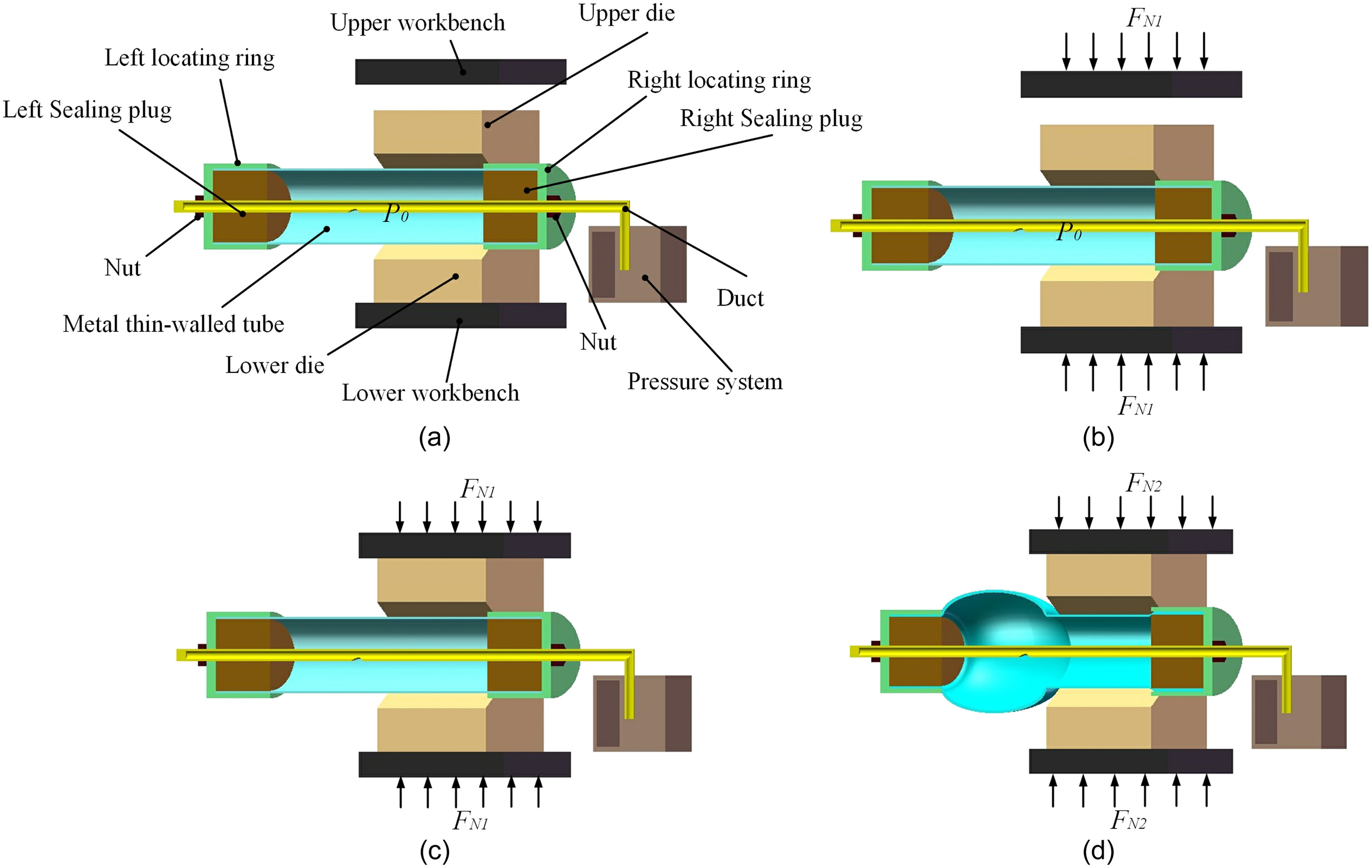
The principle of LIF of metal thin-walled tubes is shown in Fig. 1 and are performed in the following steps: (1) the tube is sealed and placed in the die, (2) the tube is filled with the liquid, while the internal pressure remains at , and (3) the upper and lower dies are closed by applying the impact load of the hydraulic press. Compound deformation occurs rapidly in the tube closing area under the action of internal pressure and die force . Natural deformation occurs only in the natural bulging area under the action of internal pressure . (4) At the end of die closing, the internal pressure is and the tube billet bulges into the required shape. The shape functions of LIF is nonlinear and large displacement.
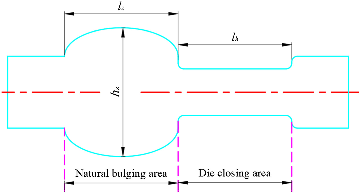
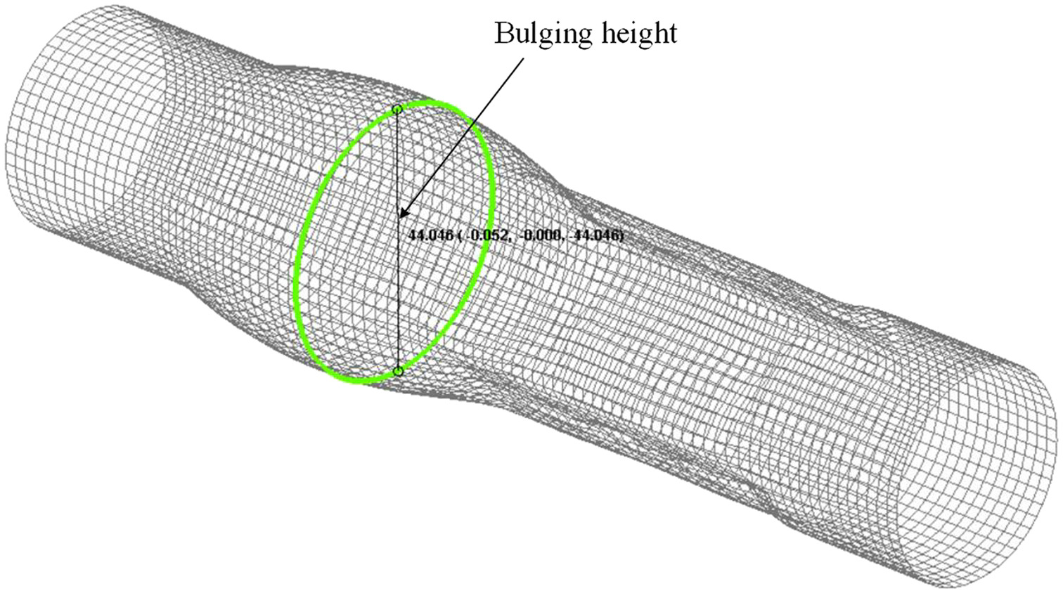
After the completion of tube bulging, the deformation area of the tube is the die closing area and the natural bulging area, as shown in Fig. 2. The composite deformation of the tube in the die closing area is mainly caused by the die closing force and the internal pressure, while the natural bulging area is mainly caused by the internal pressure. is the length of the natural bulging area, and is the height of the natural bulging area.
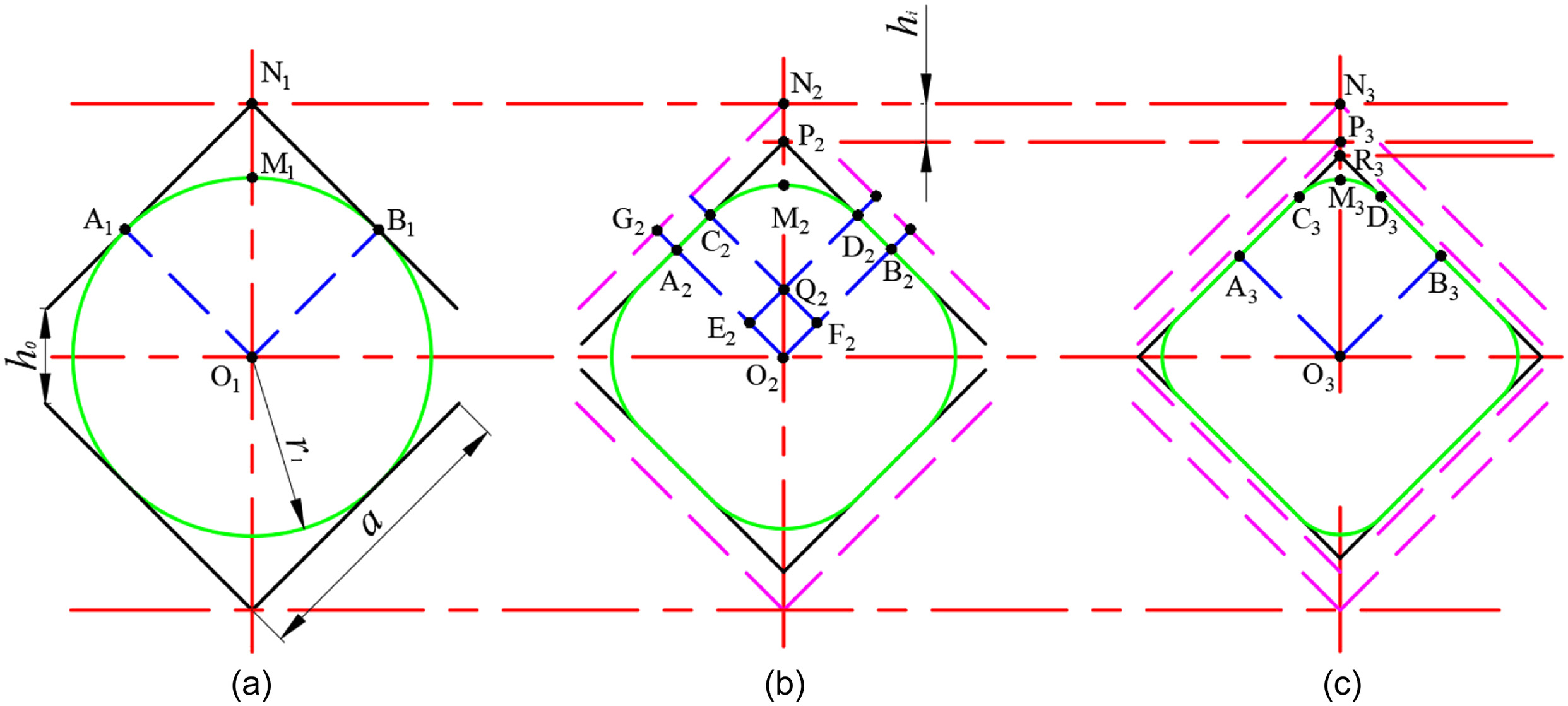
The relationship between the internal pressure and the volume of the tube blank cavity based on the liquid volume compression is shown Fig. 3. The main purpose is to obtain the internal pressure of the compressed tube blank cavity. The shape of the metal thin-walled tube will be changed during the impact hydraulic bulging process. The section changes at different stages of the die closing area are shown in Fig. 3 (Liu et al. 2019, 2020). Since the section of the die area of the tube is of center-symmetric structure, one quarter of the arc is taken to study the deformation of the section of the die area of the tube. Assuming that the die cavity is completely filled by the thin-walled tube, only the volume change in the die closing area is studied. The tube material is thin-walled tube, without considering the change of wall thickness. Since the mass and density of the tube do not change, the volume of the tube itself does not change. Therefore, the circumference of the billet does not change in the process of deformation, so the volume of the tube closing area iswhere = die closing height; = length of closing; = height of the die closing area at any time; and = inner diameter of thin-walled tube.
(1)
It is assumed that the natural bulging area is an ellipse, as shown in Fig. 2. The volume of the natural bulging area is the sum of the volume of the cylinder and the volume of the ellipsoid, without considering the volume changes of the connection area and the transition area is
(2)
The liquid can be compressed by external forces, and then the internal pressure will be generated spontaneously. According to the definition of the liquid volume compression factorwhere is the liquid volume compression factor, which is , is the bulk modulus. is the initial liquid volume in the metal thin-walled tube cavity. is the change of the internal pressure after the liquid is compressed, and , where and are the initial internal pressure and the internal pressure at a certain time in the tube, respectively. Therefore, the Eq. (3) can also be expressed as
(3)
(4)
According to the geometric relationship between Figs. 2 and 3, the volume change of the cavity in the die closing area and the natural bulging area of the tube iswhere = initial total length of tube deformation area. According to Eqs. (4) and (5), the internal pressure of the thin-walled metal tube can be obtained as
(5)
(6)
Finite Element Model
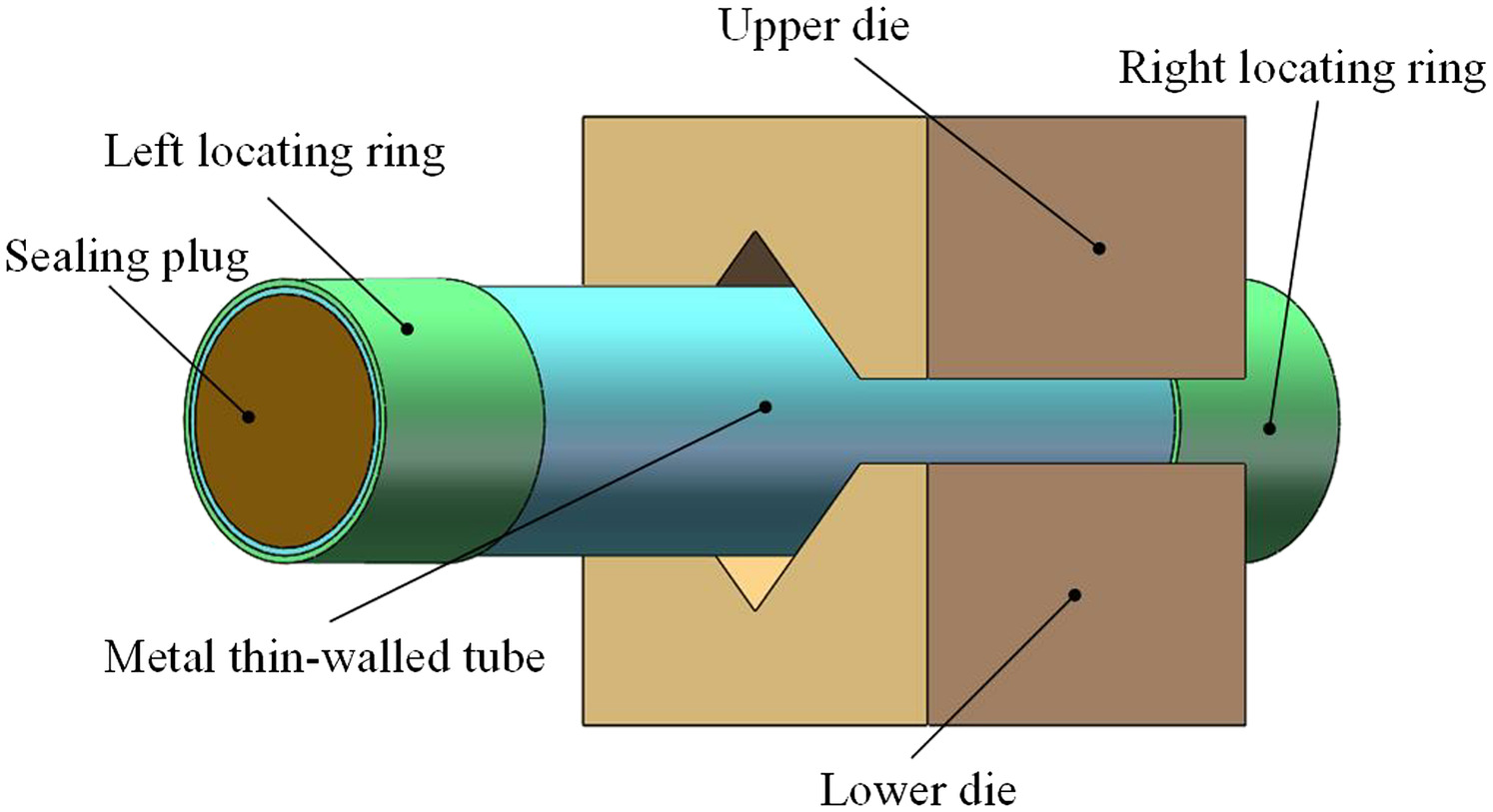
To explore the forming characteristics of the metal thin-walled tube under impact hydraulic load, the natural bulging area of tube was analyzed under the same loading conditions, the same initial parameters including the material properties, the initial wall thickness. The tube is made of 304 stainless steel. The model established by SolidWorks is shown in Fig. 4. The geometric parameters and mechanical properties of the model are shown in Table 1.
| No. | Parameters and symbols | Numerical value |
|---|---|---|
| 1 | Length of tube, (mm) | 180 |
| 2 | Length of natural bulging area, (mm) | 60 |
| 3 | Length of die closing area, (mm) | 60 |
| 4 | Initial diameter, (mm) | 38 |
| 5 | Initial wall thickness, (mm) | 0.7 |
| 6 | Yield strength, (MPa) | 205 |
| 7 | Tensile strength, (MPa) | 620 |
| 8 | Strength factor, | 1,708.4 |
| 9 | Hardening index, | 0.47 |
| 10 | Density, () | 7,930 |
| 11 | Young’s modulus, (Pa) |
ANSYS Workbench Simulation Setup
Since the internal pressure of metal thin-walled tube during LIF process is a nonlinearly changing pressure generated during the forming process, it is necessary to obtain the tube forming loading path through the transient dynamics module in ANSYS Workbench.
The model in Fig. 4 is imported into the transient dynamics module of ANSYS Workbench, and the basic parameters of the finite element model are set as shown in Table 1. The upper and lower dies, the left and right positioning rings and sealing plugs are set as rigid bodies, and the inner and outer metal thin-walled tubes are set as deformed bodies.
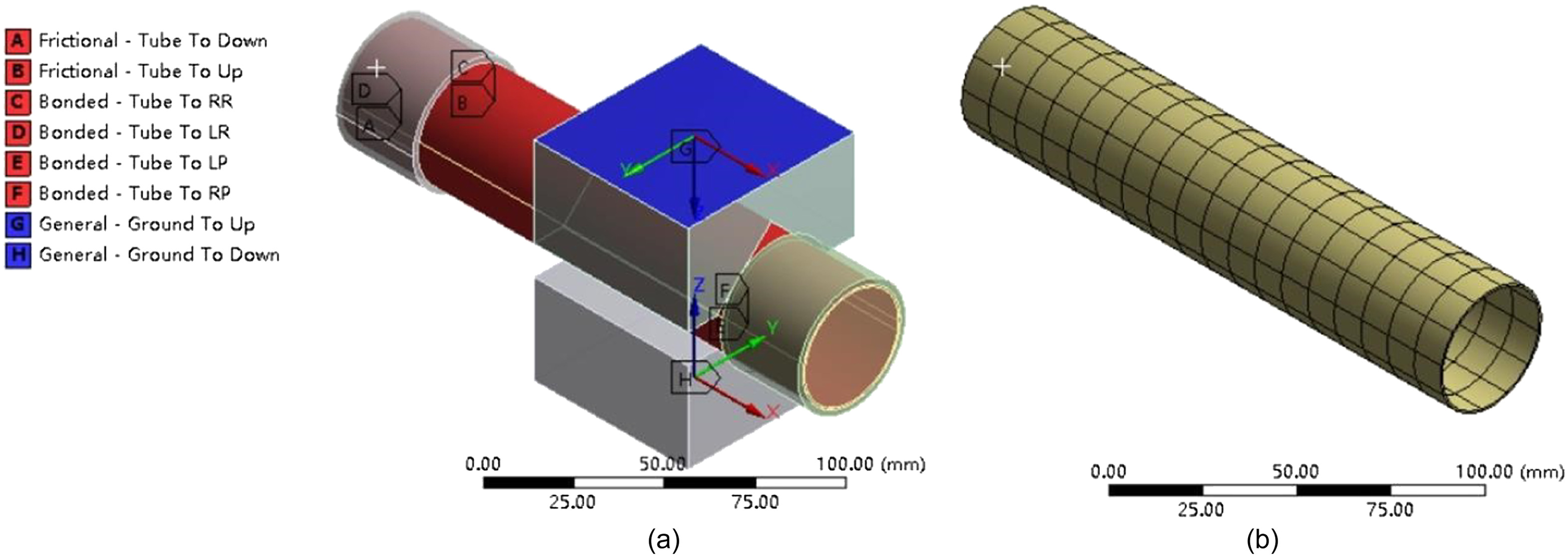
The connection setup and meshing of tube is shown in Fig. 5. In order to reduce the impact of friction, the friction coefficient between the tube and the die is 0.05 through the actual friction test. The behavior in ANSYS Workbench is set to symmetric. The tube and dies are set as frictional contacts, while tube and sealing plugs, positioning rings are set as fixed contacts. The upper and lower dies can move in the direction, and other parts are fixed. The mesh of the tube is set to Body Sizing in ANSYS Workbench, the type of body sizing is element size, and the element size is set to 6 mm.
Set four die side lengths (, , , and ) and five die closing speeds (10, 20, 30, 50, and ) as simulation conditions, the corresponding closing time and simulated maximum internal pressure are shown in Table 2.
| No. | Die side length, (mm) | Die closing height, (mm) | Die closing speed, () | Die closing time, (s) | Simulated maximum internal pressure, (MPa) |
|---|---|---|---|---|---|
| 1 | 7.070 | 10 | 0.7070 | 24.99 | |
| 2 | 20 | 0.3535 | 24.99 | ||
| 3 | 30 | 0.2357 | 24.91 | ||
| 4 | 50 | 0.1414 | 24.99 | ||
| 5 | 70 | 0.1010 | 24.95 | ||
| 6 | 6.365 | 10 | 0.6365 | 23.93 | |
| 7 | 20 | 0.3183 | 23.93 | ||
| 8 | 30 | 0.2122 | 23.93 | ||
| 9 | 50 | 0.1273 | 23.92 | ||
| 10 | 70 | 0.0909 | 23.91 | ||
| 11 | 5.655 | 10 | 0.5655 | 21.95 | |
| 12 | 20 | 0.2828 | 21.95 | ||
| 13 | 30 | 0.1885 | 21.96 | ||
| 14 | 50 | 0.1131 | 21.95 | ||
| 15 | 70 | 0.0807 | 21.95 | ||
| 16 | 4.950 | 10 | 0.4950 | 20.52 | |
| 17 | 20 | 0.2475 | 20.51 | ||
| 18 | 30 | 0.1650 | 20.53 | ||
| 19 | 50 | 0.0990 | 20.50 | ||
| 20 | 70 | 0.0707 | 20.51 |
DYNAFORM Simulation Setup
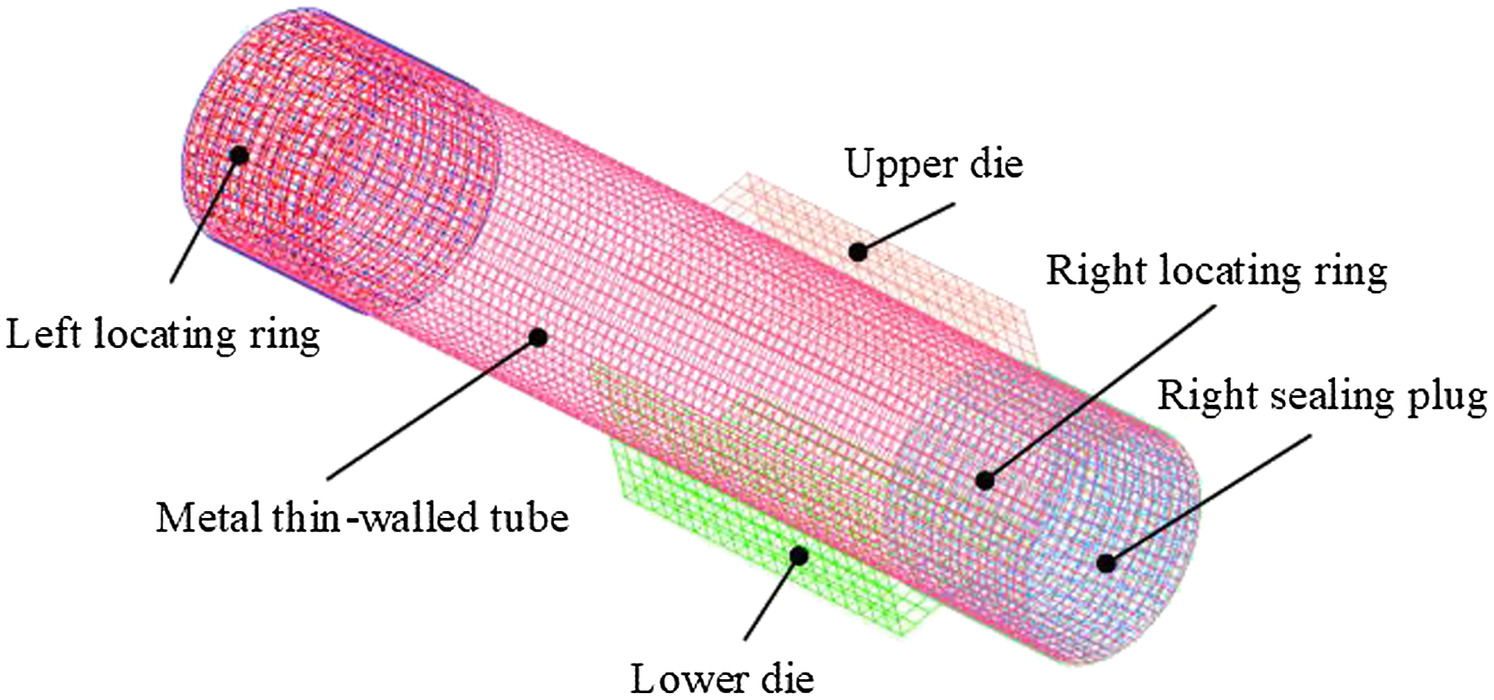
The model in Fig. 4 is imported into DYNAFORM. BT shell element is used to divide the mesh. The deformed tube is divided into quadrilateral elements, and the rigid body is divided into quadrilateral elements. The finite element model meshing is shown in Fig. 6.
The material parameters of the variable body (tube) need to be set in DYNAFORM, which is the same with ANSYS Workbench. The material parameters of the rigid body (upper and lower dies, left and right sealing plugs, left and right positioning rings) does not need to be set. The friction coefficient between the tube and dies is set to 0.05, which is also the same with ANSYS Workbench.
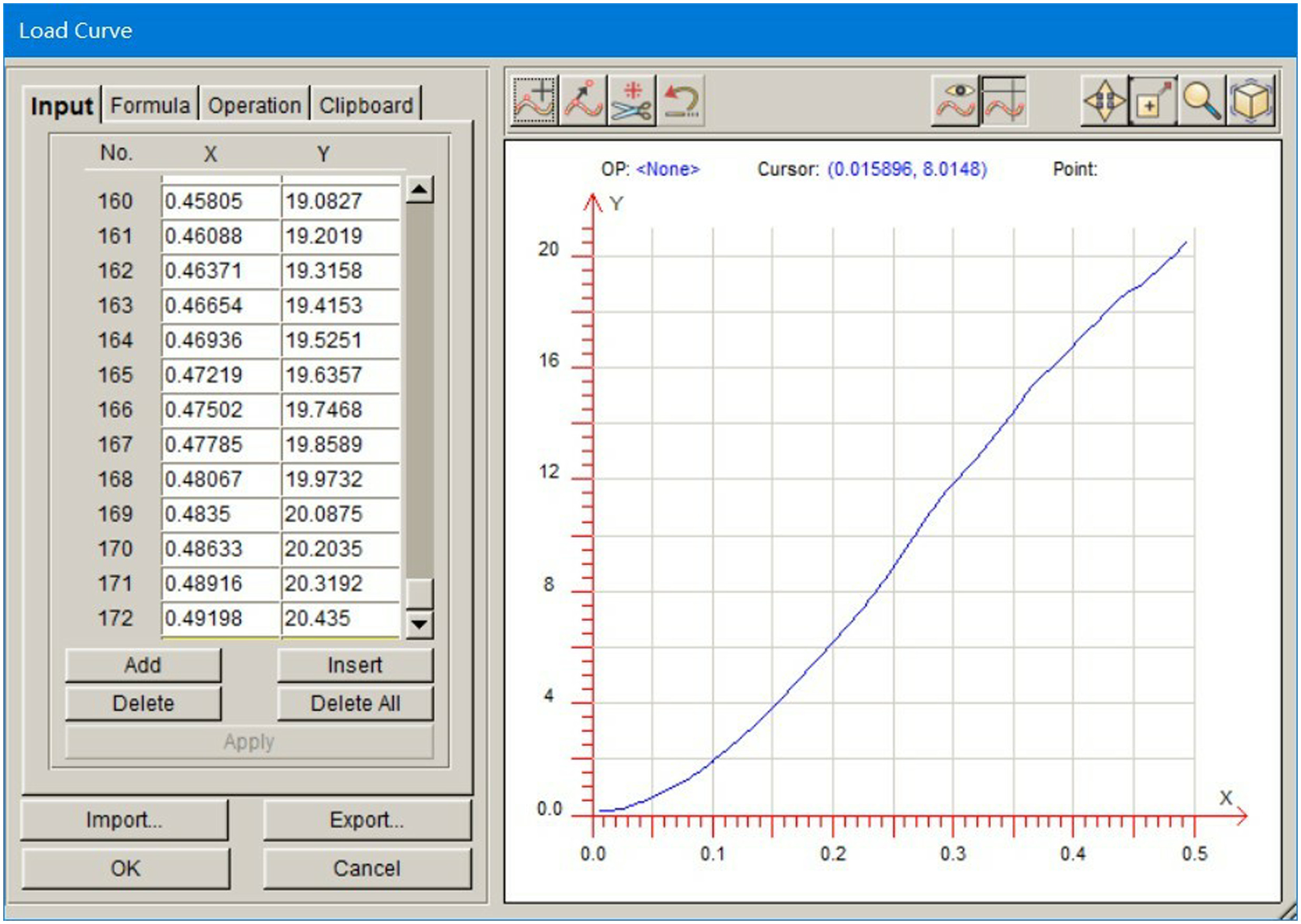
The loading path was set as nonlinear loading. The curve of internal pressure and time was obtained by ANSYS Workbench simulation. The internal pressure obtained by ANSYS Workbench simulation was converted into CSV file and imported into DYNAFORM software, as shown in Fig. 7. The node constraint is set as Z-guide (XY), and there are 3,712 constraint points in total. The deformation area includes the die closing area and the natural bulging area of the tube, and there are 6,844 deformed nodes in total.
Numerical Simulation Analysis
In order to study the forming properties of the natural bulging area of thin-walled metal tube under LIF, the influence of different loading parameters (die side length and die closing speed) on the forming properties of the natural bulging area of thin-walled metal tube, such as internal pressure, wall thickness distribution and bulging height, was systematically analyzed.
Internal Pressure
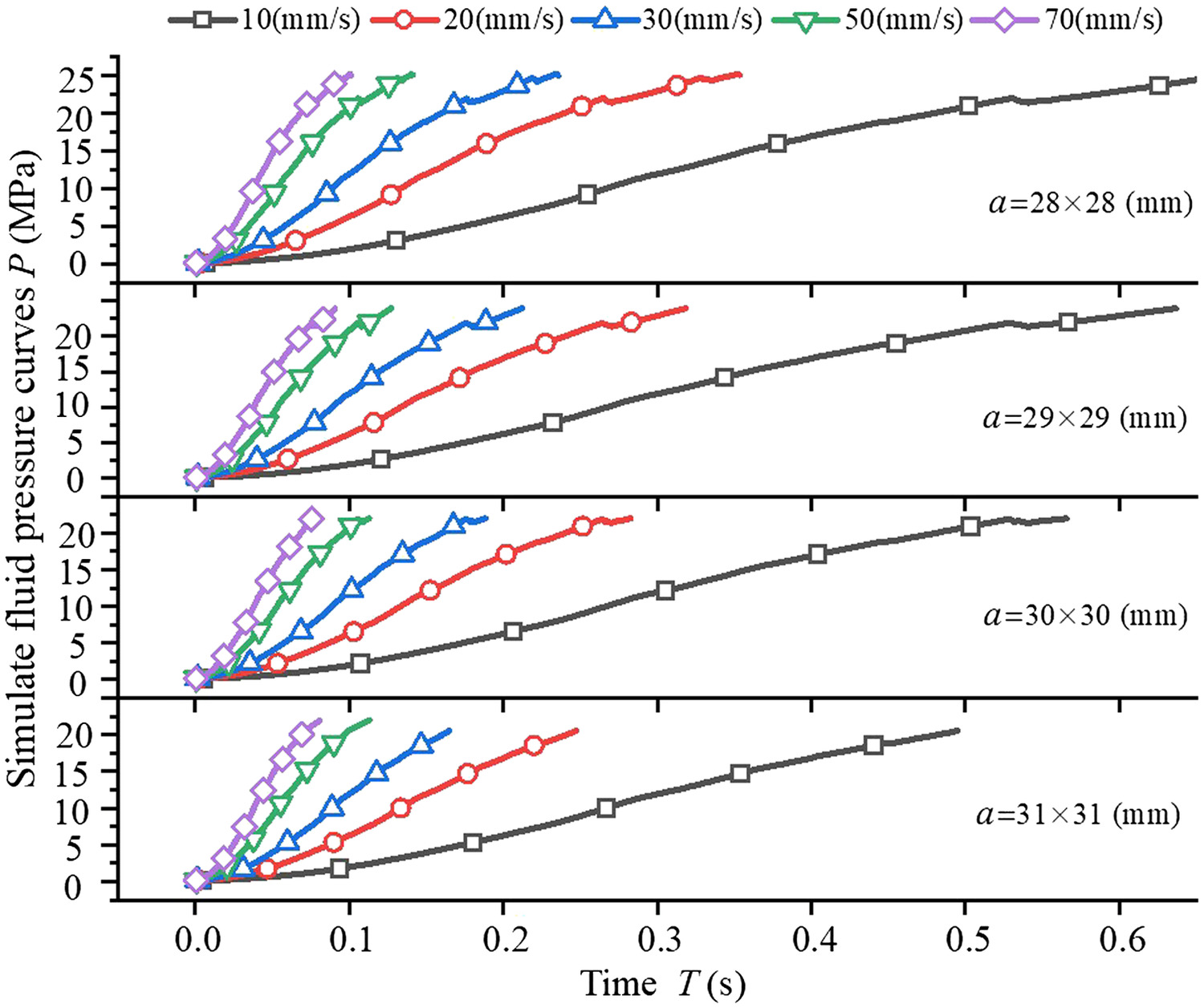
Numerical simulation analysis was carried out for tube LIF under different die closing speeds and die side lengths. Based on ANSYS, the tube internal pressure curve was obtained, as shown in Fig. 8. It is not difficult to find that the internal pressure changes have the following rules from the Fig. 8:
1.
Under the same die, with the increase of die closing speed, the die closing time is shorter, the rate of internal pressure rising is larger, and the tube forming efficiency is higher.
2.
At the beginning of die closing, the internal pressure of the tube changes slowly. In the middle and late period of die closing, the growth rate of internal pressure gradually increases, and the faster the speed, the greater the growth rate of internal pressure. The reason is that at the early stage of die closing, the volume change of the tube cavity is small, the liquid compression is small, and the internal pressure increases slowly. With the impact load, the die is closed, the volume change of the tube cavity increases, the liquid compression is large, and the internal pressure of the tube increases rapidly.
3.
At the same die closing speed, the smaller the die length, the greater the internal pressure. Under the same die, the internal pressure has no obvious relation with the die closing speed,. When the die closing speed is and the die side length is , the maximum limit internal pressure is 24.99 MPa, and when the die side length is , the minimum limit internal pressure is 20.53 MPa, the difference between them is 4.46 MPa. The reason is that the fluid pressure will increase with the increase of the cavity volume change of the tube, and the cavity volume change is proportional to the die closing height, and has no relation with the die closing speed.
Bulging Height
Bulging height, as one of the important parameters to verify the formability of tube, is mainly affected by die side length, die closing speed and internal pressure. In this section, the bulging height in the natural bulging area of the tube is analyzed as shown in Fig. 9.
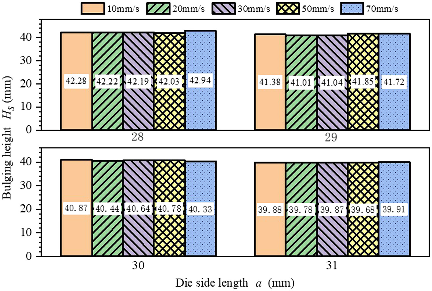
Through numerical simulation analysis of tube LIF under different die closing speeds and die side lengths, the bulging height of the natural bulging area of the tube in the last frame before the completion of bulging was obtained as shown in Fig. 10. It is not difficult to find that the bulging height of the natural bulging area changes have the following rules from the Fig. 10:
1.
When the dies are the same, the bulging height of the natural bulging area has good consistency at different die closing speeds, which show that the closing speed is not the most important factor to bulging height.
2.
At the same die closing speed, the smaller the die, the greater the bulging height of the natural bulging area of the thin-walled metal tube. The reason for this is that the fluid pressure is increased with the increase of the cavity volume change of the tube, and the cavity volume change is proportional to the die closing height.
Thickness Distribution
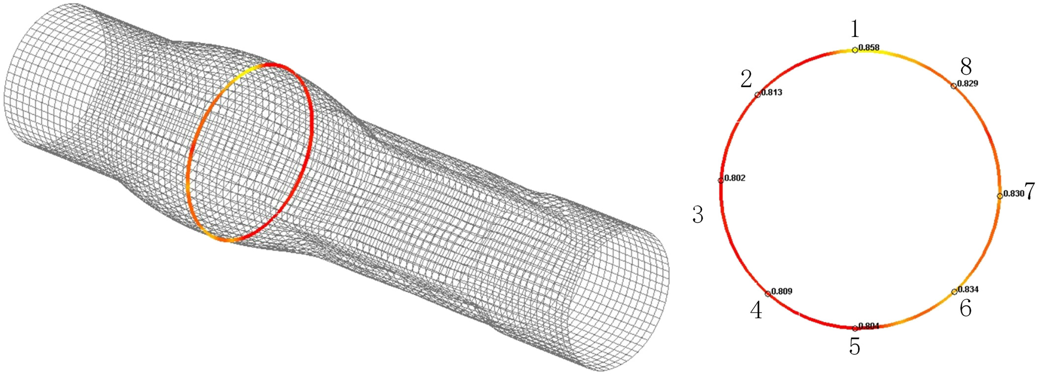
The location of wall thickness collection points is shown in Fig. 11.
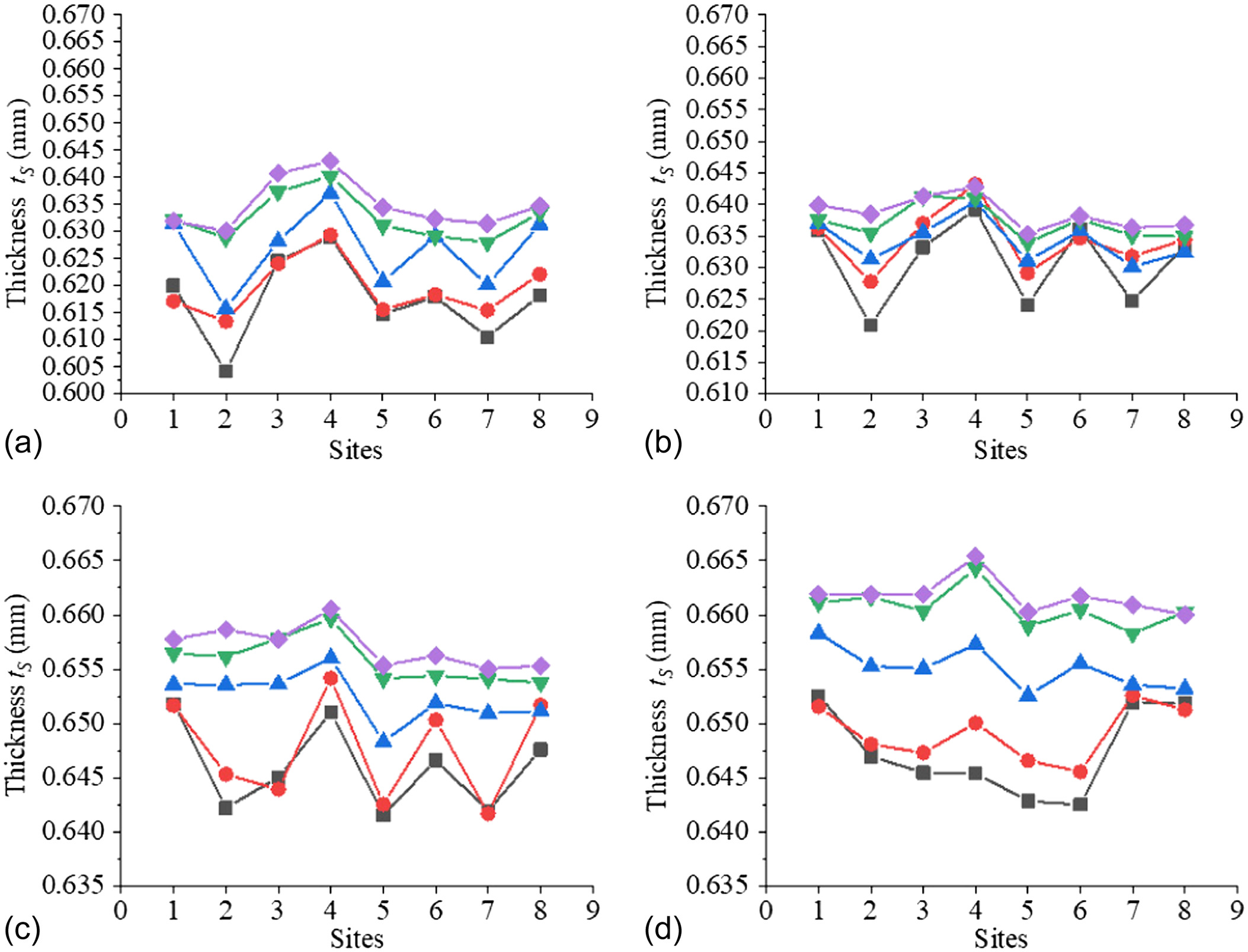
Through numerical simulation analysis of tube LIF under different die closing speeds and die side lengths, the wall thickness of the natural bulging area of the tube in the last frame before the completion of bulging was obtained, as shown in Fig. 12. It is not difficult to find that the wall thickness of the natural bulging area changes have the following rules from the Fig. 12:
1.
The distribution of wall thickness has good consistency, and the maximum deviation is about 4%, minimum deviation is about 2%.
2.
Under the same die side, the wall thickness thinning rate of the natural bulging area of the tube with the speed of is the smallest, while the wall thickness thinning rate of the natural bulging area of the tube with the speed of is the largest. The reason for this is that under the same die, the forming efficiency is proportional to the speed. The longer the forming time is, the slower the fluidity of the tube will be, and the smaller the wall thickness will be.
3.
Under the same die closing speed, the thinning rate of natural bulging area of tube with die side length of is the smallest, while the thinning rate of natural bulging area of tube with die side length of is the largest. The reason is that the smaller the length of the die side is, the smaller the change amount of the die cavity is. Under the condition of small cavity and large internal pressure, the tube bulging is more full, resulting in more serious local thinning and thickening of the tube.
Experimental Verification
Experimental Setup
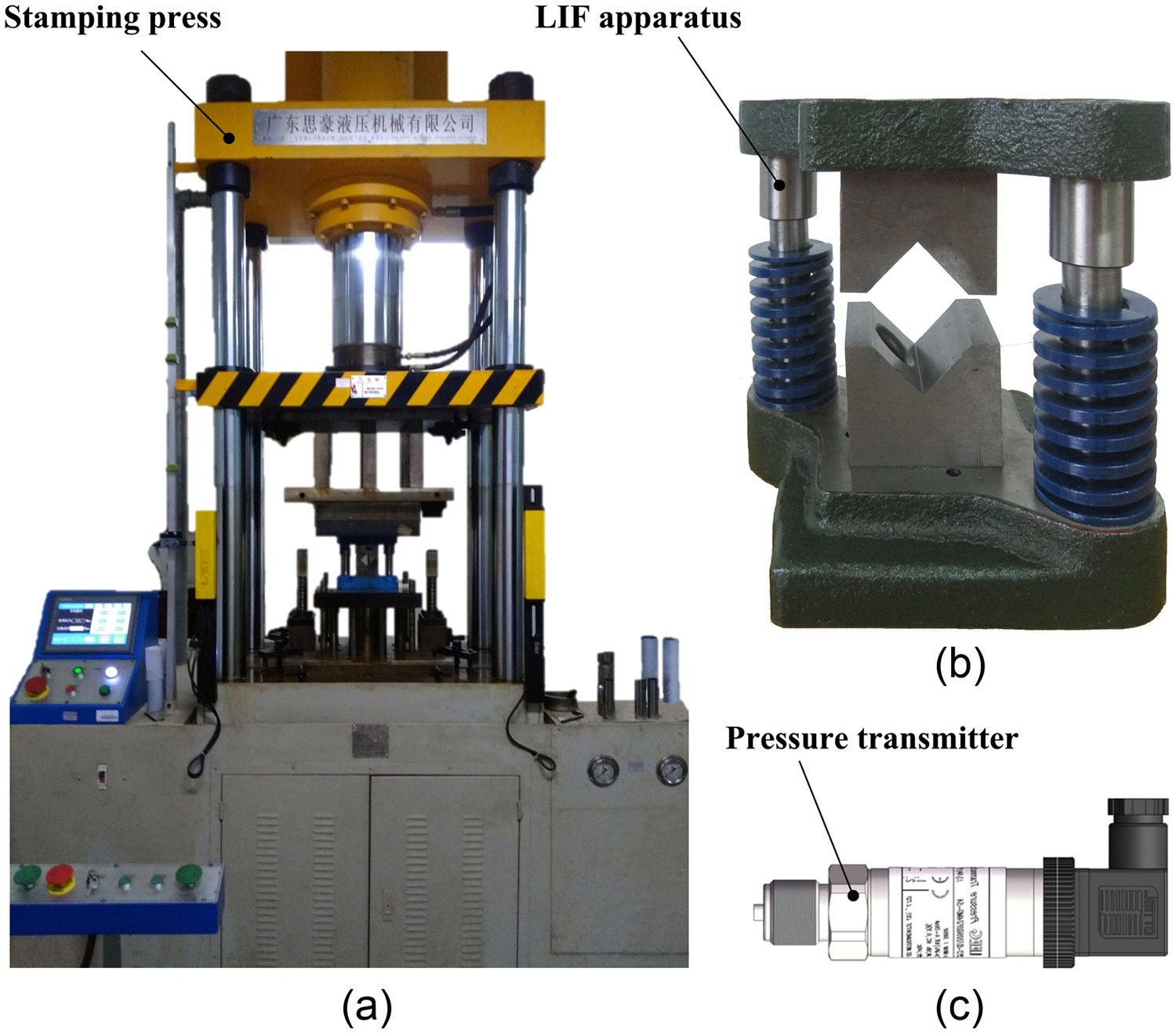
The YL32-200TA four-column hydraulic press was adopted to carry out the stamping experiment. It can be adjusted to a large range of working speeds. The LIF apparatus is used to obtain the ideal bulging shape, which is mainly composed of upper and lower templates, upper and lower dies, guide bushings, guide posts and springs, as shown in Fig. 13. Its working process is as follows: (1) Install the sealing column with hollow hole on both ends of the liquid-filled bolt, and make one end of the sealing column contact the step of the liquid-filled bolt, (2) Put the tube into both ends of the liquid-filling bolt that has been assembled with the sealing column, and make both ends of the sealing column all into the inside of the tube, (3) Put the positioning snare into both ends of the tube, lock it with nuts, and connect and fix it with the liquid-filling bolt with short hole and manual hydraulic pump, and (4) Place the assembled tube on the die.
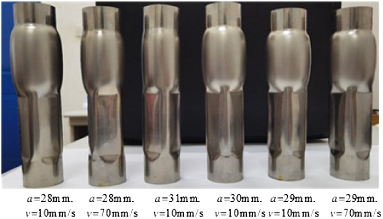
Four die side lengths (, , , and ) were used to carry out LIF tests on metal thin-walled tubes at three die closing speeds (10, 50, and ). The 304 stainless steel (SS304) thin-walled tube was used in this test. Its geometrical parameters are shown in Table 3.
| Materials | Length, (mm) | Initial diameter, (mm) | Initial wall thickness, (mm) | Length of natural bulging area, (mm) | Length of die closing area, (mm) |
|---|---|---|---|---|---|
| SS304 | 180 | 38 | 0.7 | 60 | 60 |
Results and Discussion
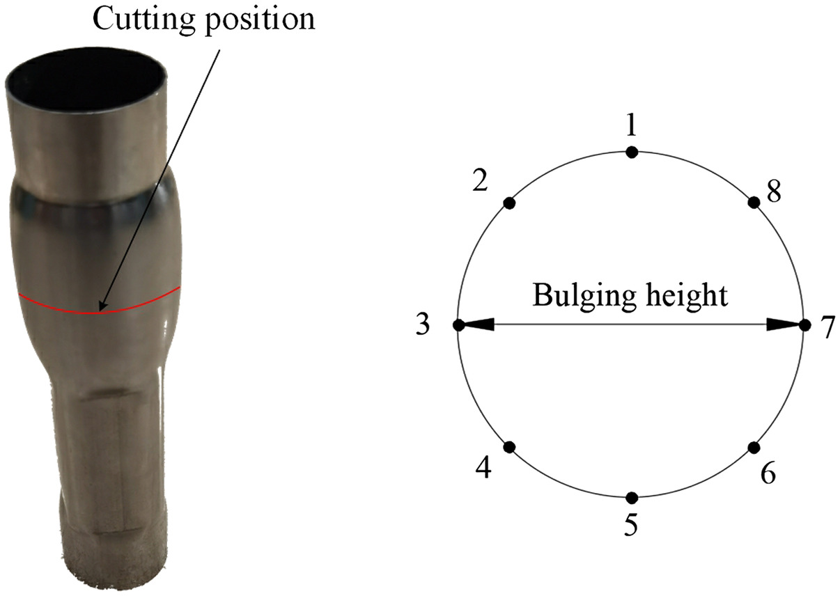
Through the LIF experiment part of the tube forming parts are obtained as shown in Fig. 14. The height of the natural bulging area of the tube with the die side length of 28 is the largest, and the height of the natural bulging area with the die side length of 31 is the smallest. The data include the internal pressure, the bulging height and the wall thickness distribution in the natural bulging area of the tube. The location of data selection is shown in Fig. 15.
Internal Pressure
The internal pressure value of the tube is observed by the pressure gauge, as shown in Table 4. It can be known from the test that in the SS304 thin-walled tube LIF under four kinds of dies and three kinds of speeds the smaller the die side length, the greater the internal pressure value. And the maximum internal pressure value has no direct relationship with the speed. The maximum internal pressure measured values have good consistency between the test and the simulated, the deviation is within 5%. There is a small difference between the data in Experiment maximum internal pressure and simulated maximum internal pressure, and the error rate of both is within 3%.
| No. | Die side length, (mm) | Die closing height, (mm) | Die closing speed, () | Experiment maximum internal pressure, (MPa) | Simulated maximum internal pressure, (MPa) |
|---|---|---|---|---|---|
| 1 | 7.070 | 10 | 24.9 | 24.99 | |
| 2 | 50 | 24.7 | 24.99 | ||
| 3 | 70 | 24.7 | 24.95 | ||
| 4 | 6.365 | 10 | 23.9 | 23.93 | |
| 5 | 50 | 23.6 | 23.92 | ||
| 6 | 70 | 23.8 | 23.91 | ||
| 7 | 5.655 | 10 | 22.9 | 21.95 | |
| 8 | 50 | 22.8 | 21.95 | ||
| 9 | 70 | 22.6 | 21.95 | ||
| 10 | 4.950 | 10 | 21.1 | 20.52 | |
| 11 | 50 | 21.5 | 20.50 | ||
| 12 | 70 | 21.4 | 20.51 |
Bulging Height
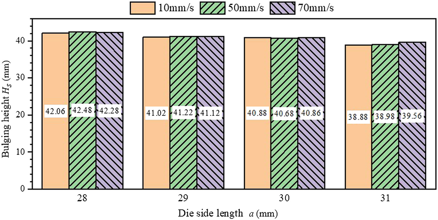
The bulging height of natural bulging area of SS304 thin-walled tube is shown in Fig. 16. It is not difficult to find that the bulging height of the natural bulging area changes have the following rules from the Fig. 16:
1.
Under the same die, there is no obvious relation between the die closing speed and the bulging height of the natural bulging area of the tube.
2.
At the same die closing speed, the smaller the die, the greater the bulging height of the natural bulging area of the thin-walled metal tube. When the die closing speed is and the die side length is , the maximum bulging height of the natural bulging area of the tube is 42.06 mm, and the minimum bulging height of the natural bulging area of the tube is 38.88 mm when the die side length is .
3.
It has good consistency from the conclusions obtained between the experimental and numerical simulation. The data deviation of bulging height in the natural bulging area is less than 5%. There is a small difference between the data in Fig. 16 and that in Fig. 10, and the error rate of both is within 3%.
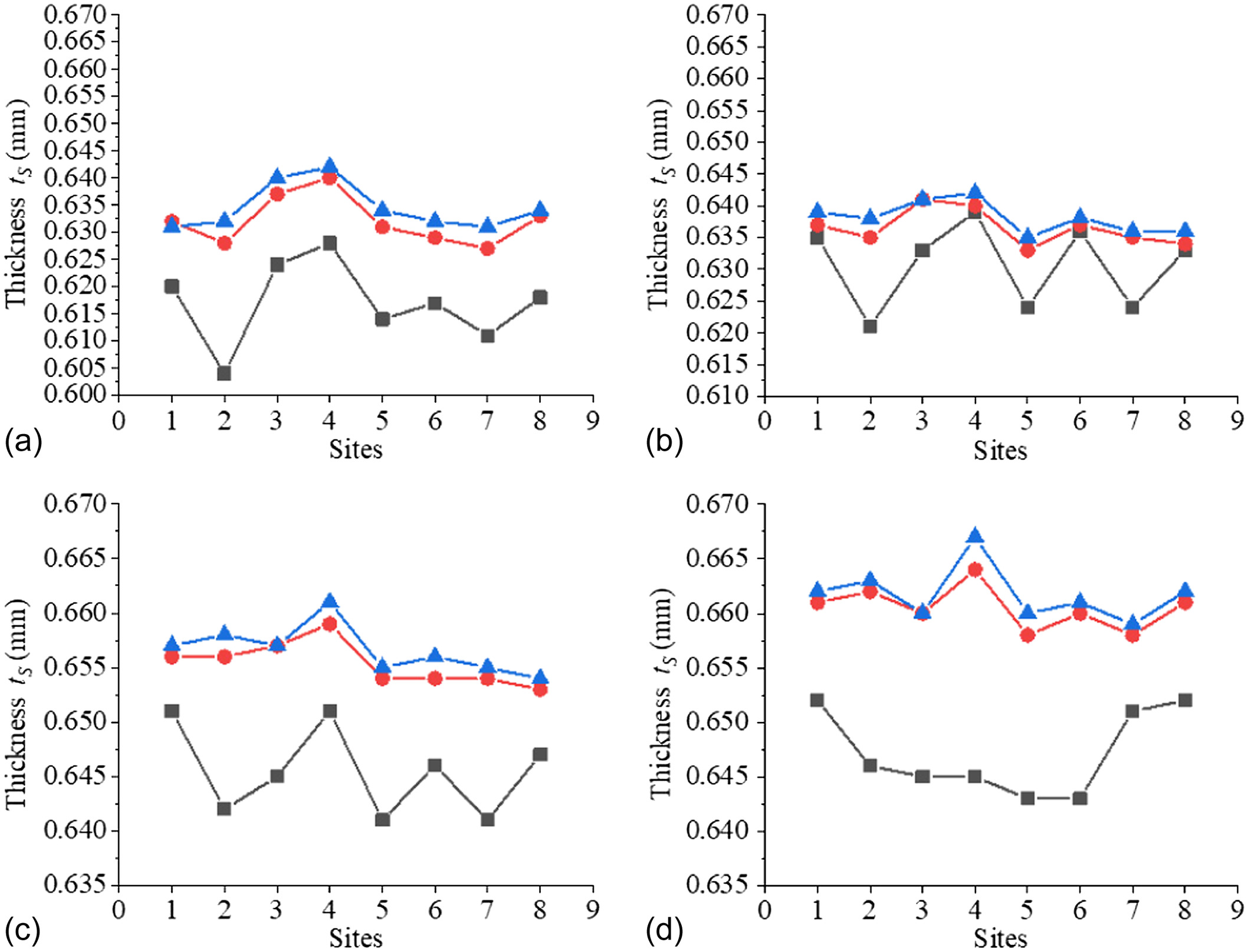
Thickness Distribution
The wall thickness of natural bulging area of SS304 thin-walled tube is shown in Fig. 17. In the figure. is the wall thickness of natural bulging area of tube. It is not difficult to find that the wall thickness of the natural bulging area changes have the following rules from the Fig. 17:
1.
Under the same die closing speed, the thinning rate of natural bulging area of tube with die side length of is the smallest, while the thinning rate of natural bulging area of tube with die side length of is the largest.
2.
Under the same die side, the wall thickness thinning rate of the natural bulging area of the tube with the speed of is the smallest, while the wall thickness thinning rate of the natural bulging area of the tube with the speed of is the largest.
3.
It has good consistency from the conclusions obtained between the experimental and numerical simulation. The data deviation of bulging height in the natural bulging area is less than 6%. There is a small difference between the data in Fig. 17 and that in Fig. 11, and the error rate of both is within 4%.
Conclusions
In this paper, the theoretical analysis, numerical simulation and experimental study on the forming of thin-walled metal tube were carried out based on the LIF. The influence of internal pressure and different load parameters on the forming performance of the natural bulging area of the thin-walled metal tube was analyzed and verified by the LIF test. The main research conclusions are as follows:
1.
Based on the relationship between the volume change of the tube cavity and the internal pressure, a mathematical model of the internal pressure of the thin-walled metal tube was established
2.
Under the same die length, with the increase of die closing speed, the die closing time is shorter, the rising rate of internal pressure is larger, and the tube forming efficiency is higher. At the early stage of die closing, the internal pressure value of the tube changes slowly, but in the middle and late stage of die closing, the growth rate of the internal pressure gradually increases, and the faster the speed, the greater the growth rate of the internal pressure.
3.
When the edges of the die are the same, there is no obvious correlation between the die closing speed and the bulging height in the natural bulging area of the tube. At the same die closing speed, the smaller the length of the die side, the greater the bulging height of the natural bulging area.
4.
The wall thickness distribution of each collection point has a good consistency, and has good symmetry along the horizontal section of the tube. Under the same die closing speed, the thinning rate of natural bulging area of tube with die side length of is the smallest, while the thinning rate of natural bulging area of tube with die side length of is the largest. Under the same die side, the wall thickness thinning rate of the natural bulging area of the tube with the speed of is the smallest, while the wall thickness thinning rate of the natural bulging area of the tube with the speed of is the largest.
Data Availability Statement
Some or all data, models, or code that support the findings of this study are available from the corresponding author upon reasonable request.
Acknowledgments
This study was financially supported by the National Natural Science Foundation of China (Grant No. 52265044), Guangxi Natural Science Foundation (Grant No. 2022GXNSFAA035586), and the National Natural Science Foundation of China (Grant Nos. 51765013 and 52065014). The authors would like to take this opportunity to express their sincere appreciation to these funding organizations.
Author contributions: Xiangwen Fan: conceptualization, methodology, investigation, software, validation, writing—original draft, writing—review and editing, and visualization. Jianwei Liu: conceptualization, overall planning, supervision, writing—review and editing, project administration, and funding acquisition. Huiping Liang: validation, formal analysis, and supervision. Zhenpeng Meng: resources, investigation, formal analysis, and data curation. Changying Sun: resources, investigation, software, formal analysis, and validation.
References
Cui, X. L., B. G. Teng, and S. J. Yuan. 2021. “Hydroforming process of complex T-shaped tubular parts of nickel-based superalloy.” CIRP J. Manuf. Sci. Technol. 32 (Jan): 476–490. https://doi.org/10.1016/j.cirpj.2021.02.001.
Cui, X. L., X. S. Wang, and S. J. Yuan. 2014. “Deformation analysis of double-sided tube hydroforming in square-section die.” J. Mater. Process. Technol. 214 (7): 1341–1351. https://doi.org/10.1016/j.jmatprotec.2014.02.005.
Cui, X. L., X. S. Wang, and S. J. Yuan. 2015. “The bulging behavior of thick-walled 6063 aluminum alloy tubes under double-sided pressures.” JOM 67 (May): 909–915. https://doi.org/10.1007/s11837-015-1291-1.
Feng, Y. Y., Z. A. Luo, H. L. Su, and Q. L. Wu. 2018. “Research on the optimization mechanism of loading path in hydroforming process.” Int. J. Adv. Manuf. Technol. 94 (Feb): 4125–4137. https://doi.org/10.1007/s00170-017-1118-z.
Hu, G. L., C. R. Pan, and Z. Liu. 2020. “Investigation of the dynamic plastic hardening of metal thin-walled tube under liquid impact forming.” J. Mech. Sci. Technol. 150 (Jan): 535–540. https://doi.org/10.1016/j.promfg.2020.08.096.
Hwang, Y. M., and W. C. Chen. 2004. “Analysis of tube hydroforming in a square cross-sectional die.” Int. J. Plast. 21 (9): 1815–1833. https://doi.org/10.1016/j.ijplas.2004.09.004.
Li, Y. H., B. Xu, and J. W. Liu. 2021. “Construction of dynamic plastic constitutive relation of thin-walled tubes based on liquid impact forming test and genetic algorithm.” [In Chinese.] J. Plast. Eng. 28 (Mar): 139–145. https://doi.org/10.3969/j.issn.1007-2012.2021.02.019.
Liu, J. W., C. Y. Sun, Y. H. Li, X. Q. Yao, and X. W. Fan. 2020. “Relationship between internal pressure and cavity volume change based on liquid impact loading to bimetallic thin-walled tubes.” [In Chinese.] J. Mech. Strength 42 (Mar): 1146–1152. https://doi.org/10.16579/j.issn.1001.9669.2020.05.020.
Liu, J. W., X. Q. Yao, Y. H. Li, H. P. Liang, and L. F. Yang. 2019. “Investigation of the generation mechanism of the internal pressure of metal thin-walled tubes based on liquid impact forming.” Int. J. Adv. Manuf. Technol. 105 (Dec): 3427–3436. https://doi.org/10.1007/s00170-019-04476-6.
Ma, J. P., L. F. Yang, J. J. Huang, Z. B. Chen, Y. L. He, and J. Y. Jiang. 2011. “Residual contact pressure and elastic recovery of an assembled camshaft using tube hydroforming.” CIRP J. Manuf. Sci. Technol. 32 (Dec): 287–298. https://doi.org/10.1016/j.cirpj.2021.01.011.
Park, J. Y., S. W. Han, H. S. Jeong, and J. R. Cho, and Y. H. Moon. 2017. “Advanced sealing system to prevent leakage in hydroforming.” J. Mater. Process. Technol. 247 (Sep): 103–110. https://doi.org/10.1016/j.jmatprotec.2017.04.006.
Shahbazi, K. J., D. N. Seyed, and T. A. Kian. 2018. “Experimental and numerical assessment of mechanical properties of thin-walled aluminum parts produced by liquid impact forming.” Int. J. Adv. Manuf. Technol. 96 (Jun): 4085–4094. https://doi.org/10.1007/s00170-018-1828-x.
Yao, X. Q., J. W. Liu, H. P. Liang, X. W. Fan, and Y. H. Li. 2021. “Investigation of forming optimization of composite tubes based on liquid impact forming.” Int. J. Adv. Manuf. Technol. 116 (3–4): 1089–1102. https://doi.org/10.1007/s00170-021-07530-4.
Yuan, C. C., X. F. Xu, Y. B. Fan, and L. Huang. 2020. “Numerical and experimental studies on thin-walled aluminum alloy tube hydroforming using differential lubrication method.” Appl. Phys. A 126 (May): 319–331. https://doi.org/10.1007/s00339-020-03509-2.
Information & Authors
Information
Published In

Journal of Pipeline Systems Engineering and Practice
Volume 15 • Issue 1 • February 2024
Copyright
This work is made available under the terms of the Creative Commons Attribution 4.0 International license, https://creativecommons.org/licenses/by/4.0/.
History
Received: Jan 29, 2023
Accepted: Sep 1, 2023
Published online: Nov 25, 2023
Published in print: Feb 1, 2024
Discussion open until: Apr 25, 2024
Authors
Metrics & Citations
Metrics
Citations
Download citation
If you have the appropriate software installed, you can download article citation data to the citation manager of your choice. Simply select your manager software from the list below and click Download.