Experimental Design and Protocol for Standardized Measurements of Rock Erodibility in Fluvial Impact Erosion
Publication: Journal of Hydraulic Engineering
Volume 149, Issue 12
Abstract
The impacts of moving bedload particles on hydraulic structures or natural bedrock in rivers can cause substantial and sometimes fast erosion, with implications for structural stability and the morphodynamics of channels. For a given set of hydraulic and sediment load conditions (termed erosivity), erosion rates are modulated by the resistance of the substrate, which is quantified in a scaling parameter termed erodibility. In this technical note, we describe in detail an experimental setup and protocol to measure the relative erodibility of natural rocks under fluvial impact erosion. The experiments were designed to achieve four central aims: to provide (1) comparable experimental conditions by keeping erosivity as constant as possible; (2) cheap, easy-to-build, and easy-to-use experimental devices; (3) a straightforward and reproducible experimental protocol; and (4) avoid special needs in terms of space, equipment, connections or fixtures. We suggest that our design and approach can serve to provide a standardized protocol for measuring comparable data on erodibility under fluvial impact erosion of natural rocks and manmade materials in the laboratory.
Introduction
The impact of bedload particles can cause erosion of the substrate they travel across, including manmade hydraulic structures such as sediment bypass tunnels, weirs or water intakes (Mueller-Hagmann et al. 2020; Auel et al. 2017), and also natural rock (Beer and Turowski 2015; Inoue et al. 2014; Sklar and Dietrich 2001; Turowski et al. 2008). Erosion rates depend on the properties of the flow and the sediment—the erosivity—and those of the substrate—the erodibility. The erodibility and the parameters that control it are specific to each of the various erosion processes active in artificial and natural channels. Fluvial erosion and, in particular, the controls on erodibility are insufficiently understood for several reasons. First, erosion is the result of hydraulics in turbulent flows, and the granular dynamics of sediment transport, resulting in brittle fracture. This makes it physically complex, with interacting processes that are incompletely understood on their own. Second, typically, erosion happens during rare events with large magnitude, including floods and reservoir flushing, or in intensive-use, high-energy parts of a structure like penstocks or bypass tunnels (Mueller-Hagmann et al. 2020; Pells et al. 2017; Turowski et al. 2008). As a result, it is challenging to collect comprehensive data sets in the field. Yet, large datasets collected under comparable and controlled conditions are necessary to develop and test proxy methods or predictive equations. Alternatively, experimental approaches can be suitable. They allow for controlling the boundary conditions and studying individual parameters in isolation. However, they typically present a trade-off between scale, realism, and faithfulness to the modeled process on the one hand and cost, efficiency, and ease of operation on the other hand.
Erosion rates and relative values of bedrock and concrete erodibility, or geotechnical properties of the eroded substrate, have been measured in various laboratory experiments (Helbig et al. 2012; Momber 2004; Sklar and Dietrich 2001; Sunamura and Matsukura 2006; Sunamura et al. 1985). However, experimental approaches and conditions vary substantially between authors and groups, making it difficult to compare the results (Attal et al. 2006; Beer and Lamb 2021; Bramante et al. 2020; Inoue et al. 2017; Johnson and Whipple 2010; Helbig et al. 2012; Sklar and Dietrich 2001; Sunamura and Matsukura 2006). Further, often the designs, setups, and protocols are insufficiently described to reproduce all of the necessary details.
Here, we describe a design of erosion mills (Sklar and Dietrich 2001), with the aim to provide a simple experimental setup and protocol that can be used as a standardized approach to measure relative erodibility. We are dealing with the specific process of fluvially-driven impact erosion on small-scale homogenous rock samples. Thus, the method is not designed to investigate the effects of larger-scale heterogeneities such as joints and cracks, or processes that lead to fracture at a scale beyond the core scale. We have designed the experimental rig and protocol in such a way as to provide a compromise between process faithfulness and ease of use. The data measured with our approach can thus be used to investigate the range of erodibility values in natural and manmade materials, to develop and test proxy methods, and to study the erosion process and the geotechnical controls on erodibility. We have prepared all relevant information in such a way that the experiments are easy to reproduce.
Design of the Experiments
Requirements and Design Approach
In designing our experimental device, we intended to achieve four overarching aims. First, we want to keep tight control of flow and boundary conditions to keep erosivity as constant as possible. This ensures that experimental runs can be directly compared. This aim implies that easily and precisely measurable control parameters should be chosen, to keep their number to a minimum, to avoid as far as possible the need for calibration, and to use simple geometries. Second, the experimental device should be cheap and easy to build and to allow its reproduction with small effort. This aim implies that standard components should be used, as well as commonly used production techniques and simple geometries. Third, the experimental protocol should be straightforward and reproducible. This aim implies that easy handling without the need for specialized tools and equipment should be striven for, as well as standard measurement procedures with universal calibration that need a minimum of training to learn. In addition, the workflow should be linear, avoid the need to make decisions, and should be sufficiently general such that it can be applied unchanged to a wide variety of substrates. Finally, fourth, it would be preferable for the experimental rig to be small while avoiding specific requirements in terms of space, fixtures, or connections (e.g., electricity, engines, water, pumps, and cooling). A desktop experiment using household power and water supply would be ideal. This would allow researchers to conduct measurements without special requirements on space and installations, and the rigs could be easily stowed away when not needed.
Erosion Mills
Erosion mills are water-filled cylinders in which the water is mobilized into rotational motion by a propeller. As a basic approach, they already fulfill a number of the requirements laid out, in particular, the simple geometry, the possibility to use standard components that are globally available, and the small number of control parameters. We build on designs previously described in the literature (Sklar and Dietrich 2001; Scheingross et al. 2014; Small et al. 2015), with some modifications to improve reproducibility and ease of handling.
Sklar and Dietrich (2001) used cylindrical metal mills with a diameter of 220 mm and a total height of around 600 mm, operated with a water depth of 490 mm above the sample. The propeller was positioned at a height of 320 mm above the sample, with the shaft entering from the top and running along the central axis of the cylinder. Several mills were connected by shafts to a single motor and could only be operated in parallel. Detailed construction sketches or information on materials and components were not provided.
Here, we adapt the fundamental experimental approach of erosion mills according to the aims laid out (Fig. 1, Table 1). We implemented the following main changes in comparison to the design of Sklar and Dietrich (2001). (1) We decreased the height of the cylinder to 228 mm. This reduces the amount of material needed to build the mills and therefore costs. In addition, it increases stability and makes handling easier because of the reduced weight, especially if the mills are filled with water. Preliminary experiments using a 600 mm high prototype demonstrated that the reduction in height did not substantially change the flow pattern. (2) We added a clamped, leak-proof lid. This, first, has the effect of preventing the formation of a water surface funnel. Second, by removing the excess air with a syringe, the amount of water in the mill can be precisely controlled and kept constant from run to run. Third, it prevents air entrainment into the water. It therefore helps to achieve steady and comparable experimental conditions. Fourth, the lid reduces evaporation and contamination, increasing precision in experiments with long run times, and allows chemical analysis of the mill water. (3) We used clear transparent acrylic polymer to build all parts of the mill. This makes direct observation of the flow and sediment transport possible and allows for estimating total erosion from the turbidity of the water. (4) We equipped each mill with its own electric motor. Thus, each mill can be operated individually, allowing run times to be matched to the observed sample erosion.
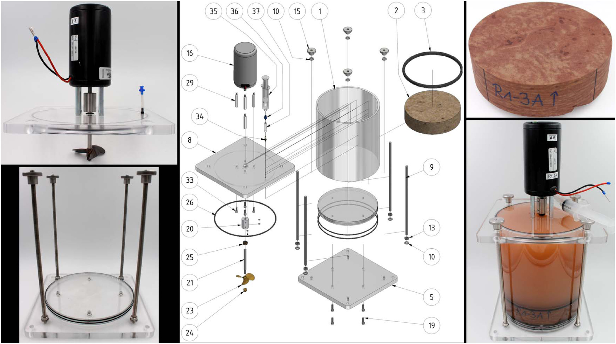
| Object no. | Part |
|---|---|
| 1 | Acrylic tubing |
| 2 | Rock sample |
| 3 | Sealing O-ring |
| 5 | Base plate |
| 6 | Round base plate |
| 7 | Base sealing O-ring |
| 8 | Lid |
| 9 | Threaded rod |
| 10 | Washer |
| 13 | Hexagonal nut |
| 15 | Knurled nut |
| 16 | Electric motor |
| 19 | Allen screw |
| 20 | Rigid coupling |
| 21 | Propeller shaft |
| 23 | Propeller |
| 24 | Prop cone |
| 25 | Shaft sealing |
| 26 | Lid sealing |
| 29 | Distance bolts |
| 33 | Allen screw |
| 34 | Fitting |
| 35 | Syringe |
| 36 | Fitting |
| 37 | Silicone tubing |
We used standard acrylic polymer (polymethyl methacrylate, PMMA) cylinders with an outer diameter of 220 mm and a wall thickness of 6 mm (Fig. 1). The material is impervious to corrosion and sufficiently tough to provide a long-lasting experimental setup. The inner diameter of 208 mm allows samples to be sourced using a standard 200 mm core bit while leaving sufficient play to handle the samples and avoid jamming. The cylinder (object #1) sits on a base plate (object #5) and is closed by a lid (object #8) that are clamped together by four threaded rods (object #9). A round base plate (object #6) with an o-ring sits inside the cylinder underneath the sample to make the connection watertight. Full construction details and a technical drawing are given in Appendix I.
As abrasive tools, we use readily available and inexpensive glass beads with a diameter of 6 mm, originally designed for the grinding of pigments (Table 2). Glass beads have the advantage over natural rocks of having a well-defined spherical shape, helping keep the experimental conditions constant and reducing shape effects. For each experiment, two bead sets of 150 g or about 530 beads each are prepared to run in alternation. This is close to the mass that yields the maximum erosion rate observed in previous experiments (Sklar and Dietrich 2001).
| Parameter | Value |
|---|---|
| Manufacturer | Glaswarenfabrik Karl Hecht |
| GmbH & Co. KG | |
| Diameter (mm) | |
| Average mass (g/bead) | 0.28 |
| Specific weight () | |
| Mohs hardness | 6 |
| Microhardness Vickers and Rockwell () | 970–1,018 |
| Elasticity module (MPa) | 7.75 |
| Young’s modulus (GPa) | 78–85 |
| Crushing strength (N) | 3,600 |
| Chemical composition | 61%–67% , 10%–18% , |
| 5%–10% CaO, 3%–8% , | |
| 1%–5% , 0.5%–3% MgO |
Experimental Protocol
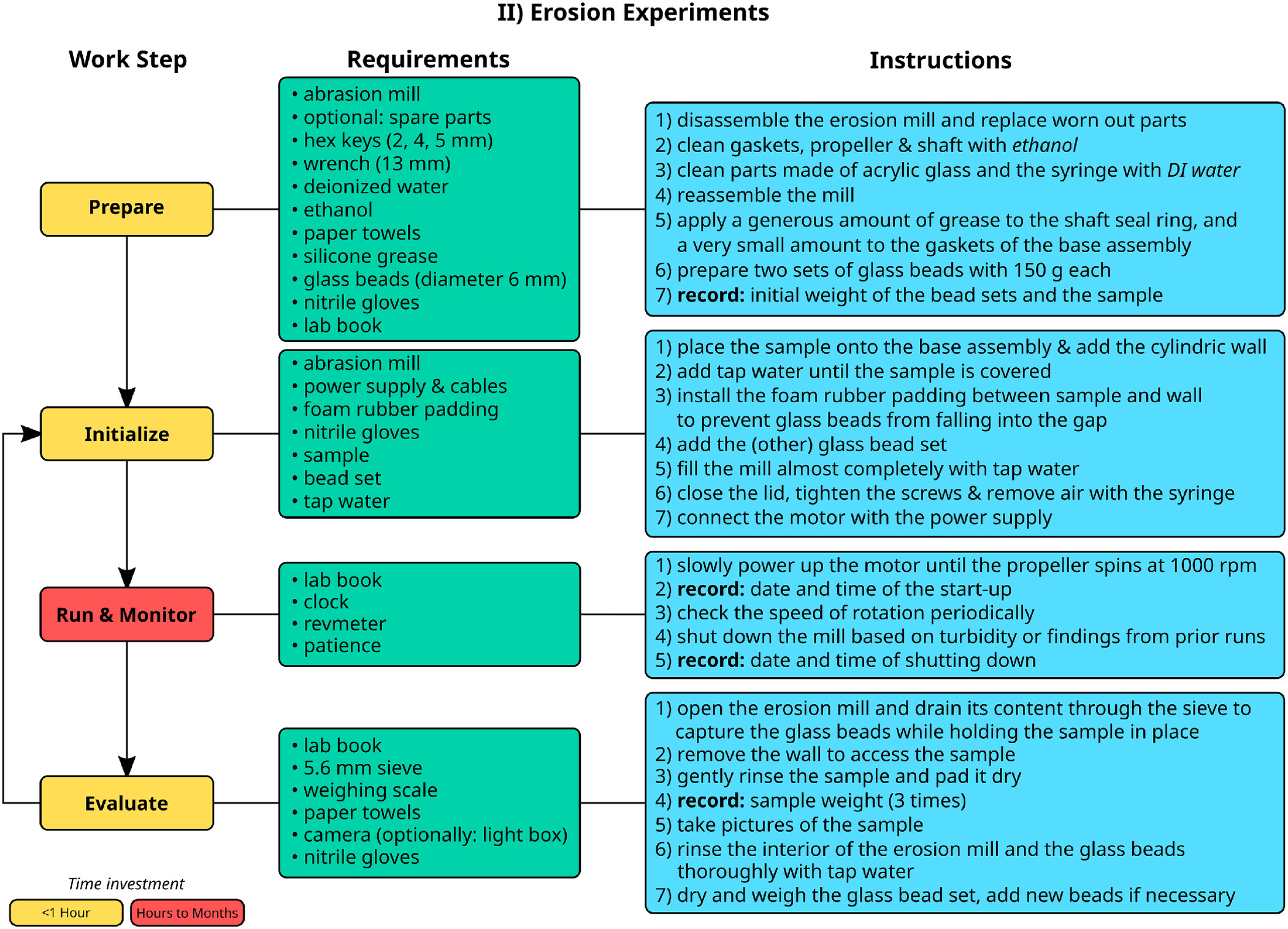
Each experiment, for a given sample, consisted of six runs with identical experimental conditions. Multiple runs allow the measurement error to be constrained and the constancy of erosivity to be tracked during experiments. The mean erosion rate of all runs is used as a representative value for the experiment, and the standard error of the mean is used as a measure of the uncertainty. Detailed instructions in step-by-step flow charts for the preparation and execution of the experiments, and the subsequent measurements, can be found in Appendix II.
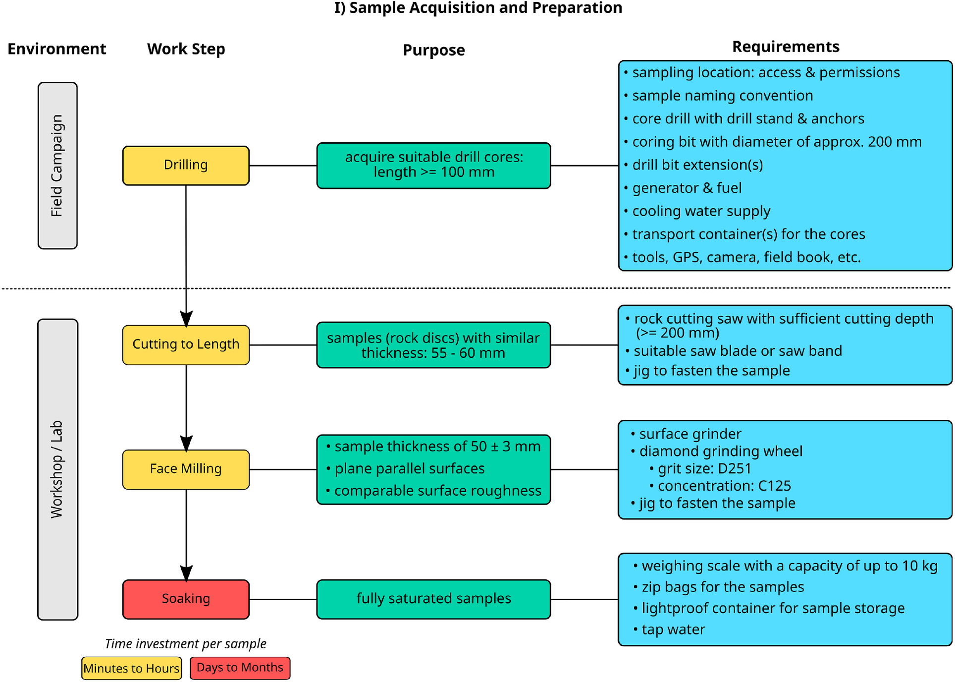
Sample Preparation
The samples used in the mill should have a diameter of around 200 mm and a thickness of about 50 mm to get samples with sufficient solidity and manageable weight. Samples were cut from cores collected in the field using a 200 mm core bit into discs with a thickness of about 55 mm. Subsequently, to ensure that both faces were planar, parallel, and had a similar surface roughness, samples were ground on a high-precision rotary surface grinder (GMN MPS2 R300) with a bronze-bonded, water-cooled diamond grinding wheel (grit size D251, concentration C125) to a thickness of . To avoid a gain of mass and a change of erosional properties by the uptake of water during the experimental runs, the samples were soaked in water before starting the experiment. Therefore, samples were placed in zipper storage bags made from LDPE with about 1.8 L of tap water. Trapped air was removed and the samples were stored for at least 14 days in light-proof boxes to inhibit the growth of microorganisms like algae. For the same reason, we always used nitrile lab gloves when handling the mills, the glass beads used as abrasive sediment, and samples. For cleaning purposes, we used paper towels, ethanol (though never on acrylic glass), and/or deionized water. To check the sample mass and derive characteristic drying curves, samples were taken out of their bags and their mass was recorded over a period of 10 min. For the first five minutes, measurements were taken in intervals of 30 s and after that in intervals of 60 s. For the first measurement, we only let the bulk of the water drip off the sample. Before the second weighting, the sample was gently padded dry with a paper towel. Between all subsequent weighings, the sample was kept standing on its side to minimize the contact area with the workspace. Samples were considered to be ready for experiments when their mass varied only slightly in two successive measurements. A flow chart summarizing all information for sample preparation is given in Appendix I.
Mill Preparation
After taking up a sufficient amount of water, the sample is placed into the cleaned mill and the gap between the sample and the mill wall is closed with foam rubber padding. The padding prevents the abrasive tools from falling into the gap and secures the sample against movement. The mill is then filled with tap water to the brim, and the abrasive tools, i.e., the glass beads, are added. After mounting the lid, excess air is removed with the attached syringe. Prior to the first run of an experiment, the mill was left for about 24 h before starting the experiment to allow the specimen to compensate for reduced water content due to the previous weighing procedure.
Experimental Runs
For each run, we aimed for a mass loss of 5–10 g. Too small a change would be hard to detect, but too large a change impair comparability between runs due to incision. Therefore, run time needs to be adjusted depending on the erosion rates and can vary between 4 h for weak sandstones or mudstones and for crystalline rocks. The turbidity of the water can serve as a first-order approximation for the speed of erosion for previously untested rocks (Fig. 1).
During runs, the mills should be regularly checked for outages, leakage, propeller speed, and unusual behavior like the detachment of larger pieces of debris from the sample. The driveshaft of the mounted DC motor is accessible from the top, and its rotation speed can be monitored with a tachometer (we use a VOLTCRAFT DT-30LK) and stepped up or down when necessary. In our setup, shaft speed usually fluctuated in the range from 990 rpm to 1,010 rpm, probably due to small voltage fluctuations in the power supply or the increase in motor temperature during operation. Such fluctuations are not problematic but should be noted if the mentioned range is exceeded. The experimental protocol is depicted in a flow chart in Appendix II.
Mill Unloading and Documentation
At the end of a run, the water is emptied from the mill, and collected for filtering, if needed (see the section “Erosion Measurements”). The sample is removed, and the remaining erosion products are gently washed off. The mill is cleaned for the next run. The state of the sample is documented by photos and in the lab book, noting, for example, the removal of larger individual grains that cause local variations in surface roughness.
To keep track of bead abrasion, the bead set is oven-dried for 24 h at 40°C and subsequently weighed. Mass loss due to wear is compensated by adding or replacing glass beads. The steps in unloading mills and obtaining the data are depicted in Appendix II.
Erosion Measurements
Erosion rates were measured with two independent methods, by monitoring the mass loss of the sample (erosion rate from sample mass, ERSM), and by filtering the mill water and drying and weighing the erosion products, i.e., the concentration of solids in the mill water corrected for bead abrasion (erosion rate from the concentration of solids, ERCS). We expect that the latter method gives a more accurate result because the erosion products can be dried before weighing them, making results comparable. In addition, mass loss due to chemical erosion is excluded from the measurement. However, this method needs substantially more effort and specialized filtering equipment.
Mass Loss of the Sample
To measure the erosion rate from mass loss, the rock plate is padded dry and weighed three consecutive times after each run, after being removed from the mill. Afterwards, the sample state is documentated with photographs. The difference between the mean weight to that from before the run indicates the lost mass. The erosion rate can be calculated by dividing the mass loss by the run time. The method is prone to some sources of uncertainty. First, the water content of the rock may change during runs, affecting the results. Drying and rewatering until saturation is not an option, since it is too time consuming, might facilitate the crack formation and introduces additional evaporative components from the tap water. Second, the water content decreases during the weighing process. Therefore three consecutive measurements are averaged after padding the specimen dry. After weighing, the sample state is documentated with photographs.
Concentration of Solids
Products from mechanical erosion are suspended in the mill water and represent the mass lost from the sample during the run. To obtain these erosion products, the mill water was filtered using a 0.2 μm PES membrane disc filter, and the captured material was oven-dried for at least 24 h at 40°C. The dry solids were weighed to a precision of 0.01 g to obtain the total eroded mass. The suspended material contains not only material detached from the sample but also from the abrasive tools. To correct this, the oven-dried beads were weighed before and after each run. Their mass loss is subtracted from the mass of captured material. The erosion rate can be calculated as the ratio of the resulting corrected lost mass and the mill run time.
Discussion and Conclusion
Mill Design
We have conducted experiments with more than 30 samples, each with six separate runs, and found that the experimental design and protocol comply with the criteria that we set out to achieve. In particular, experimental conditions are reproducible from run to run, and measured erosion rates vary little for a given sample (Fig. 2).
From our tests before arriving at the final design, we can make some statements on the important parameters to achieve comparable experimental conditions in the case the design needs to be adapted. We have tested various propeller types and also adjusted propeller height and mill height in prototypes. These changes did not have a large effect on the flow directly above the sample. The reason for this is that after a brief transitional phase, a flow field establishes that is dominantly circular with only minor vertical components. We did not investigate different mill diameters, but we expect that these have a larger effect on the flow field. In terms of the experimental protocol, the results are particularly sensitive to the details of wetting the sample before the run and the method of weighing it. This will be discussed in more detail in the following section.
Erosion Measurements
We tested 32 samples from 20 different lithologies, including sandstones, limestones, dolomites, and crystalline rocks, sourced mainly from northern Switzerland (Pruß et al. 2023). Our protocol worked successfully for all of the tested samples, apart from two samples of a clay-rich mudstone, which structurally disintegrated as soon as it was placed into the water. We therefore suggest that the approach is suitable for all materials that are structurally and chemically stable in the water for long enough to run the experiments.
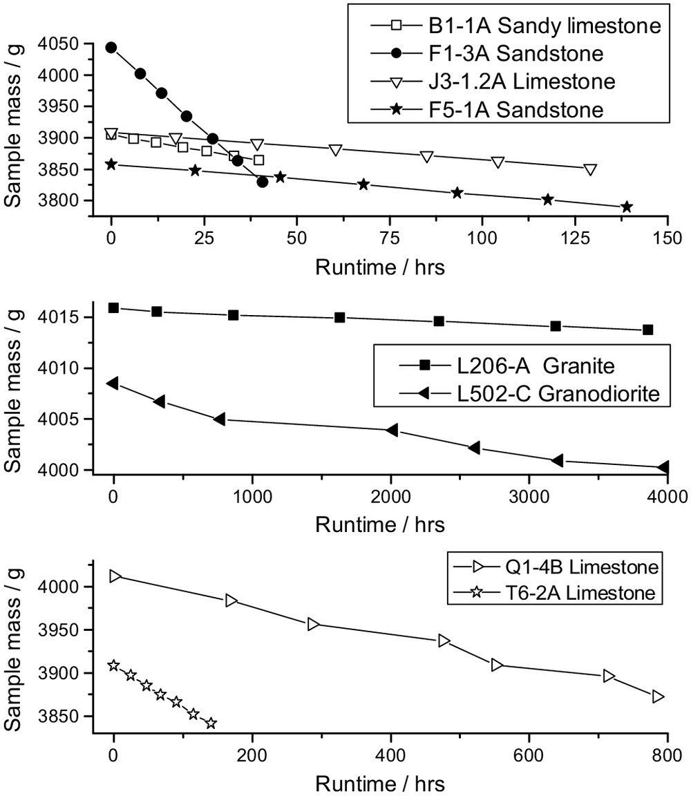
Although we aimed for a mass loss of 5–10 g in the individual runs, this was often not achieved for resistant rocks due to the necessary long run times. Runtimes for a single run varied between 3 and 1,250 h, with an average of (mean ± standard deviation, from 181 individual runs on 30 samples) and a median of 22.5 h, leading to mass losses between 0.8 and 73 g, with an average of . Typical laboratory scales can measure to a precision of 0.1 g, and often, higher precision scales are available. Thus, even small values of mass loss can result in a measurement of sufficient accuracy. Statistics of runtimes that we used for several lithological groups are listed in Table 3.
| Group | No. of units | No. of runs | Minimum (h) | Mean (h) | Maximum (h) | Standard deviation (h) |
|---|---|---|---|---|---|---|
| Crystalline | 4 | 24 | 143.5 | 681.5 | 1,247.8 | 299.1 |
| Dolomite | 2 | 18 | 5.0 | 16.0 | 24.0 | 6.0 |
| Limestone | 9 | 90 | 6.0 | 49.3 | 188.8 | 50.0 |
| Sandstone | 2 | 49 | 3.0 | 14.1 | 97.5 | 18.7 |
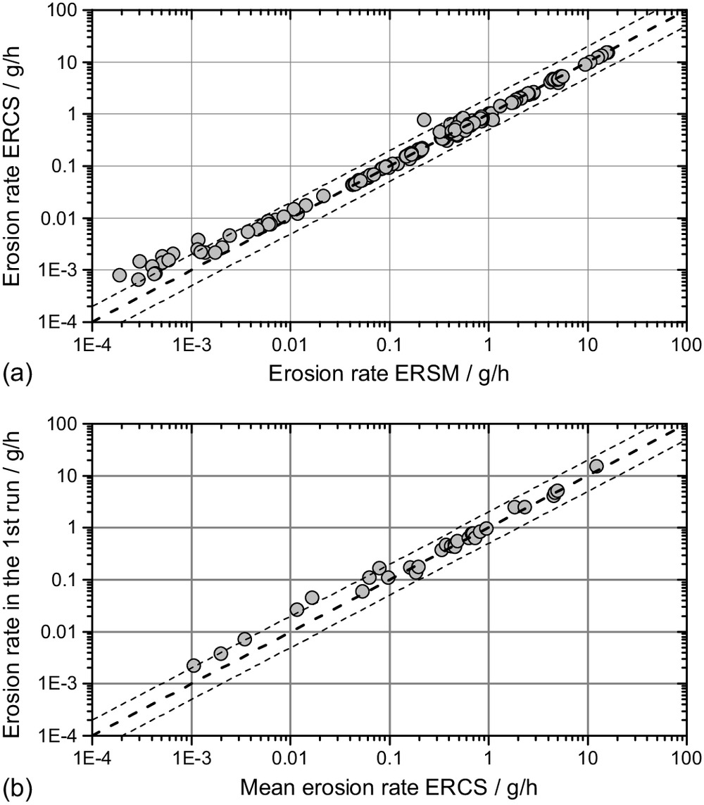
ERSM were on average and 9.75% larger than erosion rates from the concentration of solids (ERCS) (Fig. 3). Lower ERCS than ERSM rates can result from rapid evaporation of water during the weighing phase. Alternatively, sedimentary rocks with a higher erodibility typically have larger pore spaces and the weight of the water in those pores contributes to the measured mass loss. This effect leads to ERSM rates higher than ERCS rates and is probably the reason for the slight systematic bias at large measured erosion rates. Large deviations between the two values correspond typically to higher measured rates using ERCS than ERSM. This is likely due to additional water uptake by the sample, which can happen either when there is a time delay between setting up the mills and starting the run, or during long run times for hard rocks with slow erosion rates. However, the differences between the two methods are sufficiently small for ERSM to be considered reliable and suitable for measuring erodibility in most applications. In addition, there is no systematic trend in the bias for erosion rates greater than (Fig. 3). As such, the additional effort to filter the mill water, and obtaining the necessary equipment for it, is not necessary to estimate the relative erodibility of rocks. If higher precision is needed in a particular application, the ERCS method can be used. Potential uncertainties can be reduced by ensuring a sufficiently long soaking time, especially for hard, crystalline rocks, and by consistently starting experiments within 24 h after setting them up. In addition, some crystalline rocks may contain minerals such as pyrite that rapidly weather during the initial runs of the experiments. This can be addressed by conducting experiments with multiple runs and discarding the first one or two data points. However, due to long run times for crystalline rocks, this may not always be a viable option.
Concluding Statement
Within this technical note, we have described all the necessary information to accurately reproduce our experiments for measuring the erodibility in fluvial impact erosion. The appendixes contain full technical drawings of our new mill designs, including lists of the necessary parts and materials (Appendix I). CAD files are included in the supplement. In addition, we have provided flow charts for the experimental protocols (Appendix II). These can be printed out and put up in the laboratory to aid technicians, students, and scientists in conducting the experiments.
Reliable and reproducible data are necessary to advance knowledge of fluvial erosion processes and the role of the substrate in them, as well as for the development and testing of proxy methods and predictive equations. Our experimental design and protocol provide a cheap, easy-to-use, and well-documented approach to raising the required data set, while being faithful to the process of fluvial impact erosion. As such, it can provide a basis for future studies on parameters controlling bedrock erodibility in fluvial impact erosion. A detailed analysis of our experimental results is available in the paper by Turowski et al. (2023).
Supplemental Materials
File (supplemental materials_jhend8.hyeng-13346_turowski.pdf)
- Download
- 1.86 MB
Appendix I. Mill Technical Drawings
Fig. 4 gives technical details for the mills. A list of parts can be found in Table 4. CAD files and drawings of details are available in the online supplement in the Standard Exchange Protocol (STEP Version 213).
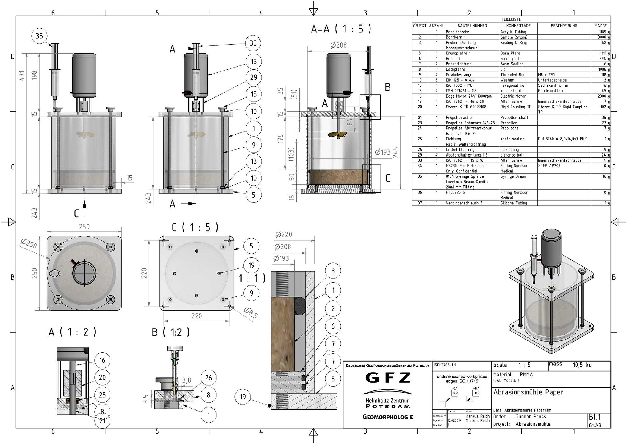
| Object no. | Quantity | CAD part name | Description | Mass (g) |
|---|---|---|---|---|
| 1 | 1 | Behälterrohr | Acrylic tubing, mill walls | 1,185 |
| 2 | 1 | Bohrkern 1 | Rock sample | 3,000 |
| 3 | 1 | Proben-Dichtung Moosgummischnur | Sealing O-ring round cord, foamed rubber | 62 |
| 10 mm EPDM 15 Shore A Schwarz/black | ||||
| Toleranzen nach DIN ISO 3302-1 E3 | ||||
| 5 | 1 | Grundplatte 1 | Base plate | 1,111 |
| 6 | 1 | Boden 1 | Round base plate | 594 |
| 7 | 2 | Bodendichtung | Base Sealing O-ring | 6 |
| NBR Shore A schwarz/black | ||||
| 8 | 1 | Deckplatte | Lid | 1,086 |
| 9 | 4 | Gewindestange | Threaded rod | 118 |
| 10 | 8 | DIN 125—A8,4 | Washer DIN 125—A8,4 | 6 |
| 13 | 4 | ISO 4032—M8 | Hexagonal nut M8 | 6 |
| 15 | 4 | CSN 021461—M8 | Knurled nut M8 | 45 |
| 16 | 1 | Doga Motor 24V 1,000 rpm | Electric motor 24V 1,000 rpm | 2,380 |
| DOGA Nr. DO16841113B04/3059 | ||||
| 19 | 4 | ISO 4762— | Allen screw | 7 |
| 20 | 1 | Starre K TR 60099108 | Rigid coupling Mädler Nr. 60099108 | 102 |
| 21 | 1 | Propellerwelle | Propeller shaft | 36 |
| 23 | 1 | Propeller Raboesch 146-25 | Propeller Raboesch 146-25 | 27 |
| 24 | 1 | Propeller Abstroemkonus Raboesch 146-25 | Propeller cone Raboesch 146-25 | 7 |
| 25 | 1 | Dichtung Radial-Wellendichtring | Shaft sealing DIN 3760 A FKM | 1 |
| 26 | 1 | Deckel Dichtung | Lid sealing D4.0 Shore 15 foamed rubber, glued | 9 |
| 29 | 4 | Abstandhalter lang M5 | Distance bolts steel | 24 |
| 33 | 4 | ISO 4762— | Allen screw | 4 |
| 34 | 1 | M5230 | Fitting Nordson Medical Nr. M5230 | 0 |
| 35 | 1 | 0134 Syringe Spritze Luerlock | Syringe Braun Omnifix 20 mL | 16 |
| Braun Omnifix 20 mL mit Fitting | Nr. 467207V | |||
| 36 | 1 | FTLL220-5 | Fitting Nordson Medical Nr. FTLL220-5 | 0 |
| 37 | 1 | Verbinderschlauch 3 | Silicone tubing diameter , length 30 mm | 1 |
| N/A | 1 | — | PEAKTECH 6226 laboratory power supply unit, 0-30 V, 0-10 A, stabilized | 2,600 |
| N/A | 1 | — | Laboratory power connection cable | 100 |
Appendix II. Experimental Protocol Flow Charts
The flow charts presented here are intended to ease the reproduction of the experimental protocol. They give step-by-step instructions and lists of the necessary material for sample preparation (Fig. 5) and for conducting the experimental runs (Fig. 6).
Data Availability Statement
All data, models, or code that support the findings of this study are available from G. Pruß, J. M. Turowski, M. Reich, M. Naumann, A. Voigtländer, A. Bonnelye, and A. Ludwig, parallel data of rock geotechnical properties and erodibility using erosion mills. GFZ Data Services, https://doi.org/10.5880/GFZ.4.6.2023.002, 2023 (Pruß et al. 2023).
Acknowledgments
We thank the GFZ workshop team headed by Alexander Lachmann for building the erosion mills and for advice on design and production. Fergus McNab and Andreas Ludwig gave helpful comments on a previous draft of the manuscript. This project was funded by NAGRA and supported by Florian Kober and Angela Landgraf.
References
Attal, M., J. Lavé, and J. P. Masson. 2006. “New facility to study river abrasion processes.” J. Hydraul. Eng. 132 (6): 624–628. https://doi.org/10.1061/(ASCE)0733-9429(2006)132:6(624).
Auel, C., I. Albayrak, T. Sumi, and R. M. Boes. 2017. “Sediment transport in high-speed flows over a fixed bed: 2. Particle impacts and abrasion prediction.” Earth Surf. Process. Landforms 42 (9): 1384–1396. https://doi.org/10.1002/esp.4132.
Beer, A. R., and M. P. Lamb. 2021. “Abrasion regimes in fluvial bedrock incision.” Geology 49 (6): 682. https://doi.org/10.1130/G48466.1.
Beer, A. R., and J. M. Turowski. 2015. “Bedload transport controls bedrock erosion under sediment-starved conditions.” Earth Surf. Dyn. 3 (3): 291–309. https://doi.org/10.5194/esurf-3-291-2015.
Bramante, J. F., J. T. Perron, A. D. Ashton, and J. P. Donnelly. 2020. “Experimental quantification of bedrock abrasion under oscillatory flow.” Geology 48 (6): 541–545. https://doi.org/10.1130/G47089.1.
Helbig, U., H. B. Horlacher, J. Stamm, C. Bellmann, M. Butler, and V. Mechtcherine. 2012. “Modeling hydroabrasive stress in the laboratory experiment, part 2—Correlation with wear values and prognosis approaches.” [In German.] Bautechnik 89 (5): 320–330. https://doi.org/10.1002/bate.201200013.
Inoue, T., N. Izumi, Y. Shimizu, and G. Parker. 2014. “Interaction among alluvial cover, bed roughness, and incision rate in purely bedrock and alluvial-bedrock channel.” J. Geophys. Res. Earth Surf. 119 (10): 2123–2146. https://doi.org/10.1002/2014JF003133.
Inoue, T., S. Yamaguchi, and J. M. Nelson. 2017. “The effect of wet-dry weathering on the rate of bedrock river channel erosion by saltating gravel.” Geomorphology 285 (May): 152–161. https://doi.org/10.1016/j.geomorph.2017.02.018.
Johnson, J. P., and K. X. Whipple. 2010. “Evaluating the controls of shear stress, sediment supply, alluvial cover, and channel morphology on experimental bedrock incision rate.” J. Geophys. Res. Earth Surf. 115 (2): F02018. https://doi.org/10.1029/2009JF001335.
Momber, A. W. 2004. “Wear of rocks by water flow.” Int. J. Rock Mech. Min. Sci. 41 (1): 51–68. https://doi.org/10.1016/S1365-1609(03)00075-3.
Mueller-Hagmann, M., I. Albayrak, C. Auel, and R. M. Boes. 2020. “Field investigation on hydroabrasion in high-speed sediment-laden flows at sediment bypass tunnels.” Water 12 (2): 469. https://doi.org/10.3390/w12020469.
Pells, S. E., K. Douglas, C. Auel, and P. J. N. Pells. 2017. “Rock mass erodibility.” J. Hydraul. Eng. 143 (5): 06016031. https://doi.org/10.1061/(ASCE)HY.1943-7900.0001243.
Pruß, G., J. M. Turowski, M. Reich, M. Naumann, A. Voigtländer, A. Bonnelye, and A. Ludwig. 2023. Parallel data of rock geotechnical properties and erodibility using erosion mills. Potsdam, Germany: GFZ Data Services. https://doi.org/10.5880/GFZ.4.6.2023.002.
Scheingross, J. S., F. Brun, D. Y. Lo, K. Omerdin, and M. P. Lamb. 2014. “Experimental evidence for fluvial bedrock incision by suspended and bedload sediment.” Geology 42 (6): 523–526. https://doi.org/10.1130/G35432.1.
Sklar, L. S., and W. E. Dietrich. 2001. “Sediment and rock strength controls on river incision into bedrock.” Geology 29 (12): 1087–1090. https://doi.org/10.1130/0091-7613(2001)029%3C1087:SARSCO%3E2.0.CO;2.
Small, E. E., T. Blom, G. S. Hancock, B. M. Hynek, and C. W. Wobus. 2015. “Variability of rock erodibility in bedrock-floored stream channels based on abrasion mill experiments.” J. Geophys. Res. 120 (8): 1455–1469. https://doi.org/10.1002/2015JF003506.
Sunamura, T., and Y. Matsukura. 2006. “Laboratory test of bedrock abrasion by sediment-entrained water flow: A relationship between abrasion rate and bedrock strength.” Trans. Jpn. Geomorphological Union 27 (1): 85–94.
Sunamura, T., Y. Matsukura, and H. Tsujimoto. 1985. “A laboratory test of tractive abrasion of rocks in water.” Trans. Jpn. Geomorphological Union 6: 65–68.
Turowski, J. M., N. Hovius, M. L. Hsieh, D. Lague, and M. C. Chen. 2008. “Distribution of erosion across bedrock channels.” J. Br. Geomorphological Res. Group 33 (3): 353–363. https://doi.org/10.1002/esp.1559.
Turowski, J. M., G. Pruß, A. Voigtländer, A. Ludwig, A. Landgraf, F. Kober, and A. Bonnelye. 2023. “Geotechnical controls on erodibility in fluvial impact erosion.” Earth Surf. Dyn. 2023 (May): 1–31. https://doi.org/10.5194/egusphere-2023-76.
Information & Authors
Information
Published In

Journal of Hydraulic Engineering
Volume 149 • Issue 12 • December 2023
Copyright
This work is made available under the terms of the Creative Commons Attribution 4.0 International license, https://creativecommons.org/licenses/by/4.0/.
History
Received: May 12, 2022
Accepted: Jun 2, 2023
Published online: Sep 26, 2023
Published in print: Dec 1, 2023
Discussion open until: Feb 26, 2024
Authors
Metrics & Citations
Metrics
Citations
Download citation
If you have the appropriate software installed, you can download article citation data to the citation manager of your choice. Simply select your manager software from the list below and click Download.
Cited by
- Jens M. Turowski, Gunnar Pruß, Anne Voigtländer, Andreas Ludwig, Angela Landgraf, Florian Kober, Audrey Bonnelye, Geotechnical controls on erodibility in fluvial impact erosion, Earth Surface Dynamics, 10.5194/esurf-11-979-2023, 11, 5, (979-994), (2023).