Deep Vibrocompaction at the Natural Frequency of the Soil Response
Publication: Journal of Geotechnical and Geoenvironmental Engineering
Volume 150, Issue 9
Abstract
Deep horizontal vibrocompaction is an efficient method of compacting granular soils that has been used and optimized over decades. The state of research indicates that the best possible compaction results are achieved when the vibrator operates at the natural frequency of the vibrator-soil interaction system. However, this approach proved to be unsustainable in practical application. This paper presents a concept for determining the soil response by means of the soil contact force and its phase angle and proposes that an optimized compaction is possible at the natural frequency of the soil response. The considerations are explained using a single-degree-of-freedom (SDOF) model. The admissibility of the approach is demonstrated using measured data as an example. The soil contact force and the phase angle of the soil response are evaluated for selected compaction tests. The evaluation shows that reducing the excitation frequency allows compaction close to the natural frequency of the soil response, requiring less electrical energy, shorter compaction time, and less jetted water. Approaching the natural frequency of the soil response promises to be a valuable criterion for optimizing the deep vibrocompaction process.
Introduction
Deep horizontal vibrocompaction (also referred to as vibroflotation) is a ground improvement technique for the compaction of granular soils. It was developed by the Johann Keller GmbH in the early 1930s and has been widely used ever since (Kirsch and Kirsch 2017). The technique is based on the rearrangement of particles into a dense state by the introduction of mainly horizontal vibration of the vibrator body, resulting in increased soil density. In addition to the reduction of the void volume, changes in the stress state of the soil also result from the increasing horizontal stresses, according to Massarsch and Fellenius (2002) and Massarsch et al. (2020). The benefits of a correctly executed deep horizontal vibrocompaction are increased soil stiffness, a homogenized subsoil, reduced settlements, and a reduction of the liquefaction potential (Kirsch and Kirsch 2017). The main advantages compared to other compaction technologies are the significantly high compaction depth and the homogeneous improvement of soil conditions along the treated depth. Vibroflotation is used for the compaction of granular soils with a comparatively low content of fines, e.g., in land reclamation projects or compaction of loose natural sediments. The practical application of this technique has been extensively discussed in the literature since the 1950s, for example, by D’Appolonia (1953), Thorburn (1975), Wehr and Sondermann (2012), and Kirsch and Kirsch (2017).
The device for deep horizontal vibrocompaction comprises the vibrator body and a variable number of extension tubes to reach the required compaction depth. A flexible coupling connects the vibrator body to the extension tubes. The compaction rig is suspended from a crane or mounted on a specifically designed base machine. An eccentric mass rotating around its vertical axis inside the vibrator body induces the horizontal vibrations of the vibrator. The motor for the eccentric mass is usually located above the mass and is electrically driven (Wehr and Sondermann 2012).
After the vibrator is lowered to the desired compaction depth, the compaction process is performed from bottom to top. During the compaction, the vibrator is either kept at a constant depth for a specified time or the vibrator is withdrawn and then lowered again by typically half the withdrawal height. For the second method, hydraulic pull-down pressure supports the penetration process by activating the dead weight of the compaction rig. This method is called the back-step procedure and is mainly used in slightly cohesive, granular soils.
The compaction success is usually assessed through conventional site investigation methods such as cone penetration tests with (CPTu) or without (CPT) pore-water pressure measurement, standard penetration tests (SPTs), or dynamic probing (DP). CPTu tests have gained worldwide acceptance for their quality control of deep vibrocompaction in recent years. They are a relatively fast and cost-effective method that provides a continuous profile along the depth and more than one reading (Robertson 2006). The application of various site investigation methods and the interpretation of the data is discussed in Robertson (2006), Bo et al. (2012), and Bałachowski and Kurek (2015). Moreover, Covil et al. (1997) and Mitchell and Solymar (1984) point out the influence of aging effects on the results of CPTu tests.
In addition to conventional site investigation, geophysical methods are an alternative way to assess the compaction success of larger areas. However, those methods are rarely used. Application examples are presented by Kim and Park (1999), Karray et al. (2010), and Bitri et al. (2013).
Site investigation methods for assessing the results of the compaction work can only be applied after the compaction work has been completed; therefore, these methods cannot be used to improve the compaction process during the actual compaction work. Moreover, the tests are often time-consuming and are characterized by the random nature of spot-like inspection methods. Therefore, researchers and construction companies have pursued the idea of a vibrator-integrated compaction control to not only evaluate the compaction success, but also control the compaction process. The basic principle of a vibrator-integrated compaction control is the recording and evaluation of process parameters and their correlation with the achieved compaction result.
Poteur (1968, 1971) measured accelerations in the compacted soil in addition to the vibrator motion during large-scale field tests and compared the results to theoretical studies. Morgan and Thomson (1983) determined the amplitude of the vibrator tip for various vibrator types to correlate the amplitude to results from dynamic probing tests. Fellin et al. (2003) presented an analytical model and compared its results to measurements of vibrator motion during compaction of sand fills. Nendza (2006) used a 1:3 scale vibrator model to investigate the influence of various machine and process parameters on the compaction effect. Model tests with a “mini vibrator” were recently also performed by Nagula and Grabe (2020). Theoretical studies by means of analytical, semianalytical, and different numerical approaches have been conducted by Arnold and Herle (2009), Fellin (2000), Nagula and Grabe (2017), Triantafyllidis and Kimmig (2019), and Wotzlaw et al. (2023). In a recent study, Nagy et al. (2021) use an analytical model to investigate the relationship between the actual soil stiffness and the vibrator motion. They present a working hypothesis that allows for an identification of dominant soil mechanical processes leading to the compaction effect in the soil.
According to Brumund and Leonards (1972), Seed and Silver (1972), and Youd (1972), the densification process in the compaction of granular soils primarily depends on the shear strain amplitude. The shear strain amplitude was also identified by Arnold and Herle (2009) as the most important factor for densification by vibroflotation. Massarsch (2023) notes that in addition to the shear strain amplitude, the number of vibration cycles also has a significant influence on the compaction process. Both the shear strain amplitude and the number of vibration cycles are influenced by machine and process parameters, e.g., the excitation frequency and the holding times determine the number of vibration cycles. The shear strain amplitude in the soil caused by deep horizontal vibrocompaction is also dependent on the excitation frequency and also, for example, on the applied tip load and the jetted water.
The term “deep vibratory compaction” is sometimes used as a collective term for horizontal and vertical vibratory compaction methods in larger depths. The interaction system of compaction equipment and soil and its resonance characteristics differ greatly, depending on the dominant direction of excitation. A comprehensive overview on deep vertical vibratory compaction is given by Massarsch (2023).
This paper focuses exclusively on deep horizontal vibrocompaction (vibroflotation). Theoretical considerations are made using a simple single-degree-of-freedom (SDOF) model to develop the novel concept of deep vibrocompaction at the natural frequency of the soil response. The presented concept has the potential for the development of an “online” control of the compaction process and the optimization of compaction by adjusting the parameters of the process during the compaction work.
Vibrator-Soil Interaction, Damped Harmonic Oscillator
Machines with a rotating-mass type of excitation can often be modeled as a damped harmonic oscillator (Chopra 2007; Studer et al. 2008). The vibrator body of a deep vibrocompaction rig is excited by an eccentric mass rotating around its vertical axis. A damped harmonic oscillator excited by a quadratic force function has therefore already been used as a modeling approach for the dynamic vibrator-soil interaction (Fellin 2000).
Fig. 1 shows the theoretical solution for a damped harmonic oscillator with a rotating-mass type of excitation. The frequency ratio in Fig. 1 is the ratio of the angular excitation frequency to the natural angular frequency of the system. The frequency ratio and the damping ratio define the amplification factor (Chopra 2007):
(1)
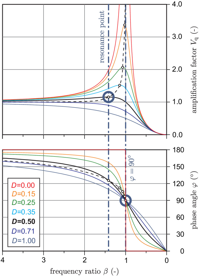
In case of a deep vibrator, the amplification factor describes the ratio of the actual amplitude of the vibrator in interaction with the soil to the amplitude of the compactor vibrating freely in the air. The phase angle represents the angle by which the direction of force of the rotating-mass type of excitation precedes the direction of the deflection amplitude . Therefore, in the following, will be referred to as the lead angle. The excitation force depends on the mass and the eccentricity of the unbalance and increases with the square of the angular excitation frequency [Eq. (2)]:
(2)
The local maxima of the amplification factor for different damping ratios are called resonance points (Fig. 1). Resonance can only be observed for a frequency ratio of if the damping ratio is . There is no amplification of the vibrator amplitude if the damping ratio is . For damping ratios , the frequency ratio associated with the resonance point is (Das and Luo 2016).
The lead angle is always 90° for a frequency ratio of under damped conditions, regardless of the magnitude of the damping ratio. Since the resonance point in the damped quadratically excited oscillator is formed at a frequency ratio of , the lead angle associated with the resonance point is always larger than 90°. The larger the damping ratio, the larger the lead angle associated with the resonance point. Nagy (2018) derived a damping ratio of from experimental investigations on deep horizontal vibrocompaction. The corresponding resonance point is marked in Fig. 1.
Vibrocompaction at the Natural Frequency of the Interaction System
The state of research utilizes the damped harmonic oscillator approach and suggests that the best possible compaction is achieved when the vibrator operates at the natural frequency of the vibrator-soil interaction system. A compaction at the natural frequency of the interaction system would be achieved at a lead angle of (Fellin 2000; Massarsch and Fellenius 2002; Wehr 2005; Nendza 2006; Wehr and Sondermann 2012; Massarsch et al. 2020). This state-of-the-art concept seems plausible: if a system is excited at its natural frequency (or at resonance), the largest (displacement) amplitudes occur with minimal force or energy input (Chopra 2007; Studer et al. 2008; Das and Luo 2016). It is reasonable to assume that the large amplitudes lead to the best compaction result.
In the scope of the GeoGlue research project, large-scale experimental tests were carried out with a M-series vibrator from the company Keller in a gravel pit in Styria, Austria, in July 2015 (Nagy 2018; Nagy et al. 2021). The vibrator was equipped with various sensors, including heavy-duty accelerometers and a pulse emitter for the determination of the current position of the rotating eccentric mass. The measurement setup allowed online determination of the lead angle , which was displayed to the machine operator. To the authors’ knowledge, this was the first time that it was possible to perform a lead-angle-controlled deep vibrocompaction. Compaction tests were carried out with a lead angle of exactly 90° by continuously adjusting the excitation frequency and tip load. The results of the tests were consistently disappointing: either the frequency had to be kept so low that hardly any compaction could be achieved, or the tip load had to be greatly increased so that the dynamic vibrator movement was overpressed. The extreme tip load created excessive strain, which can be potentially harmful to the vibrator in the long run. Furthermore, the compaction result was not satisfactory (Nagy 2018).
The empirical optimization of deep vibrocompaction, both in terms of design and application, has already reached a high standard over the decades. Now that the optimization criterion “compaction at the natural frequency of the interaction system” could be verified by measurement, it became apparent that the damped harmonic oscillator approach represents an oversimplification of the actual conditions in the soil. This concept therefore proved to be unsustainable in practical application (Nagy 2018). This finding led to further research and the development of the concept of deep vibrocompaction at the natural frequency of the soil response, which is presented in this paper. The concept was developed on the basis of a further series of experimental field tests.
Experimental Field Tests
Ground Conditions on the Test Site
Large-scale experimental field tests were conducted in 2019 in the scope of a land reclamation project in Southeast Asia. During land reclamation, a part of the sea was extensively filled with sand. This work was completed in 2005. The top of the marine sediments lies at a depth of to below sea level. The upper edge of the sand fill is approximately 4.0 m above sea level.
A core borehole (No. P3A-A15) was drilled on the test field to a depth of below ground level to investigate ground conditions in the immediate vicinity of the planned tests. The marine sediments were found at a depth of . The profile of borehole No. P3A-A15 is shown in Fig. 2. Soil samples were taken at various depths and are marked in Fig. 2 as TW.1–TW.7. The groundwater table was found at a depth of below ground level.
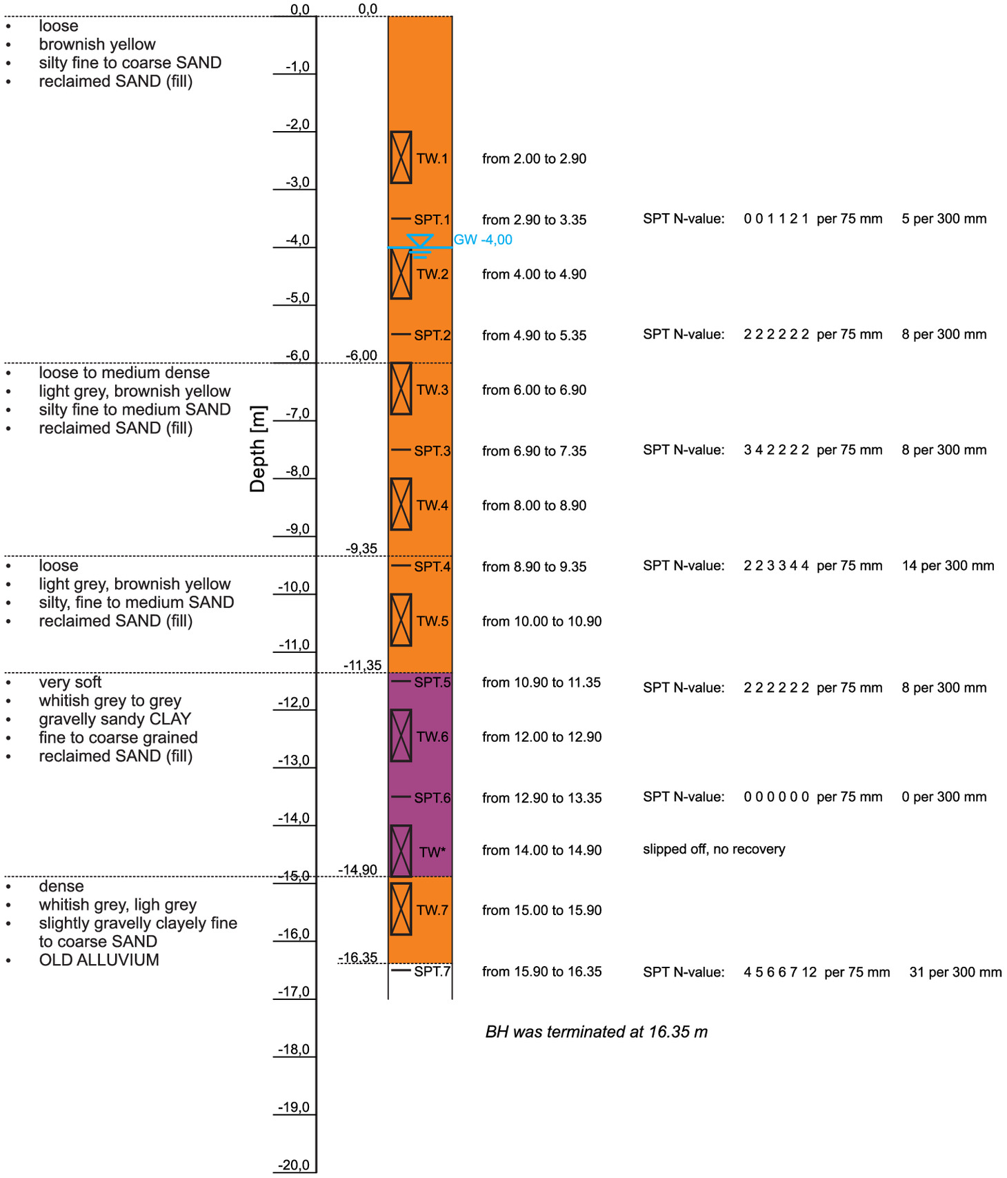
During core drilling, several standard penetration tests (SPTs) were performed. The results of the SPTs are shown in Fig. 2, each at the corresponding depth level. In the sandy fill, comparatively low values were recorded during the SPTs. In the soft clay layer on the seabed, the recorded blow counts are even lower. However, significantly higher blow counts were recorded in test No. SPT.7. In addition to taking soil samples in the sand fill, several soil samples were also taken from the backfill material. The soil samples were analyzed partly in a laboratory in Singapore and partly in the soil mechanics laboratory of the Institute of Geotechnics at the TU Wien in Vienna, where various soil parameters were determined.
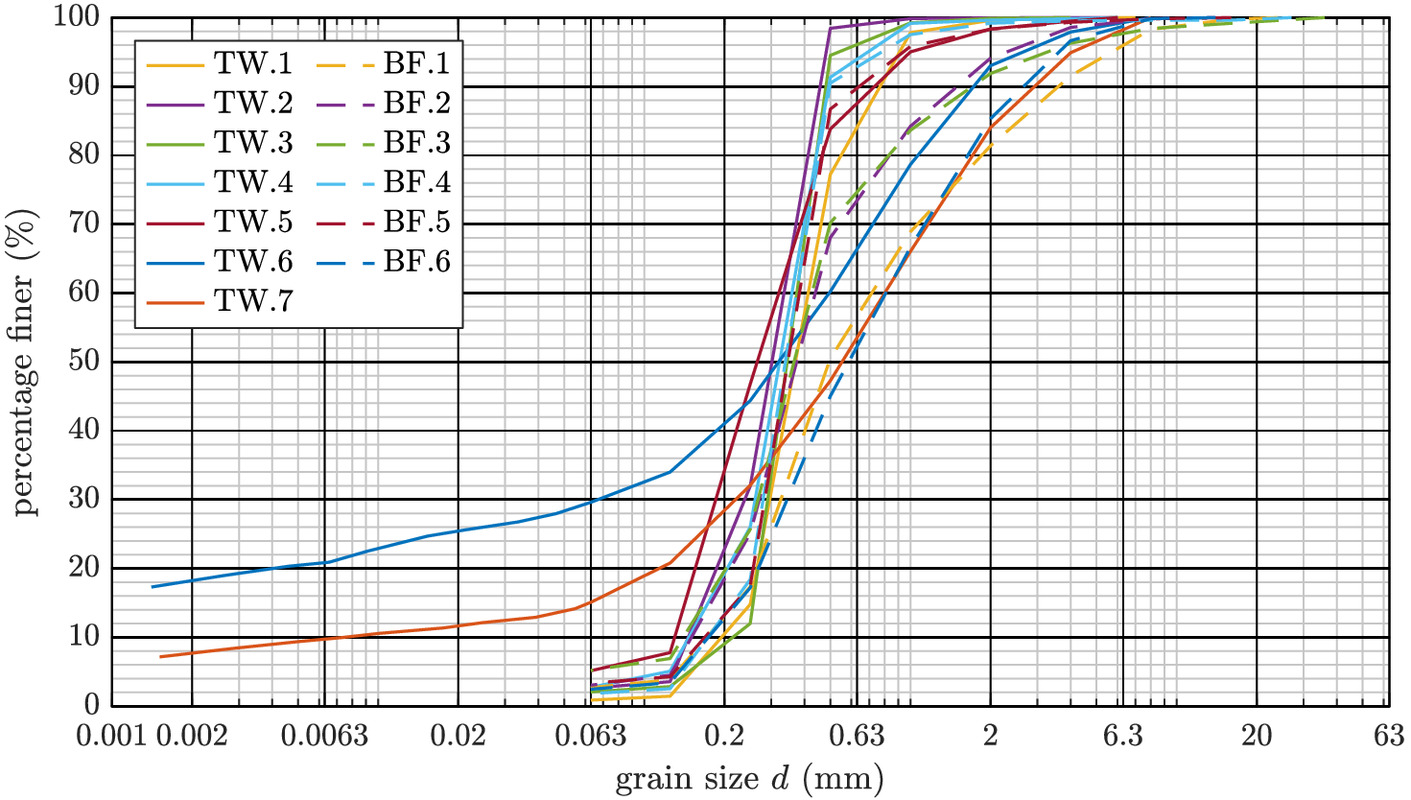
Fig. 3 shows the grain-size distribution curves of all soil samples recovered from borehole P3A-A15. Samples TW.1–TW.5 were taken from the sand fill. The grain-size distribution curves of these samples are poorly graded and have a low percentage of fines (3%–5%). Samples TW.6 and TW.7 were taken in the marine sediment. Accordingly, a higher proportion of fine grains was determined for these samples. The grain-size distribution of soil samples BF.1–BF.6, which were taken from the backfill material, varies in a wider range than that of the sand fill, but the fine grain content is also low in these soil samples.
The water content of the soil samples taken from the core borehole is comparatively high. In the partially saturated soil (sample TW.1), a water content of 12.7% was determined. In the saturated sand fill (samples TW.2–TW.5), the water content varied between 25.9% and 30.1%.
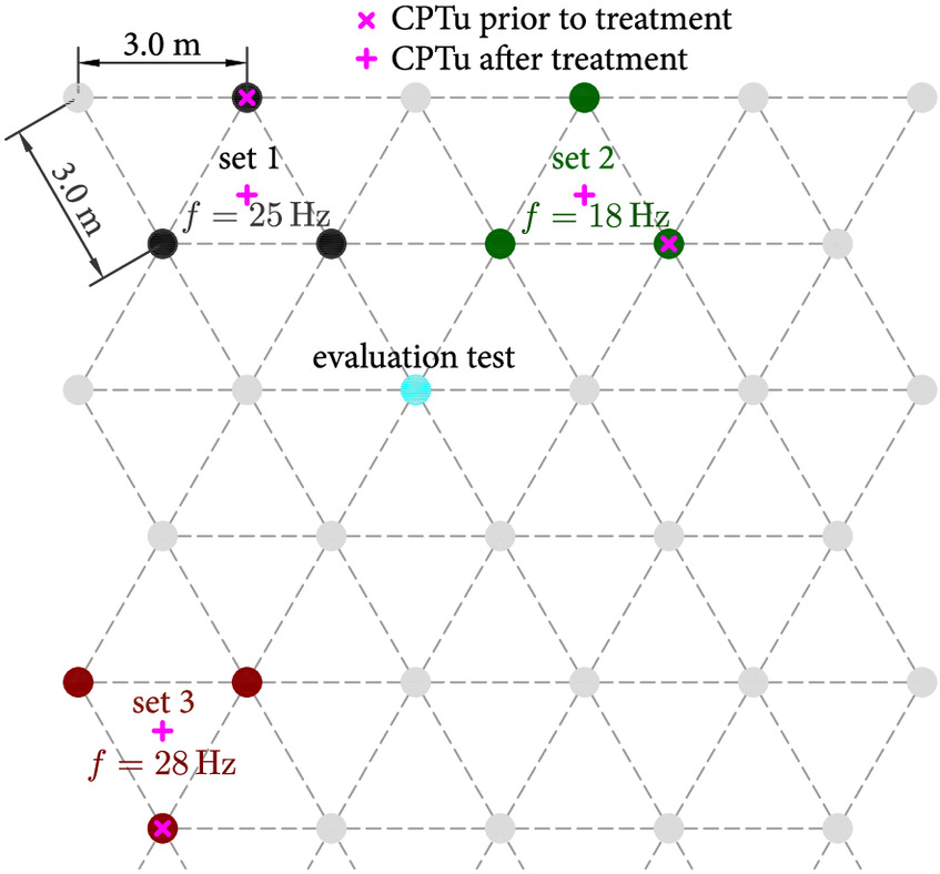
CPTu tests were exclusively used to monitor the compaction success at the test site. A total of 27 CPTu tests were done prior to the compaction tests on the test field. These tests also form an integral part of the ground exploration. The layout for the compaction points was defined as a triangular grid with a spacing of 3.0 m between the compaction points. The starting points of the CPTu tests were positioned at the location of the future compaction points in a corner of the triangular grid. Fig. 4 shows a sketch of the triangular grid and the location of the three CPTu tests prior to treatment relevant for this paper.
A full set of CPTu results for the three relevant locations is given in Fig. 5, including cone resistance, sleeve friction, friction ratio, pore pressure, and soil behavior type (), according to Robertson (1990). The cone resistance varies in a range from about 2.0 MPa to 9.0 MPa in the sand fill. Near the surface, increased cone resistances due to compaction by construction traffic are indicated by slightly higher values in isolated cases. The results of the CPTu test at the location of set 2 also show significantly higher values for sleeve friction and friction ratio near the surface. The increased friction ratio at a depth of for the test at the location of set 3 indicates a higher percentage of fines or even a cohesive soil. This inhomogeneity is also reflected in the soil behavior type, which is classified as silt mixtures at this depth.
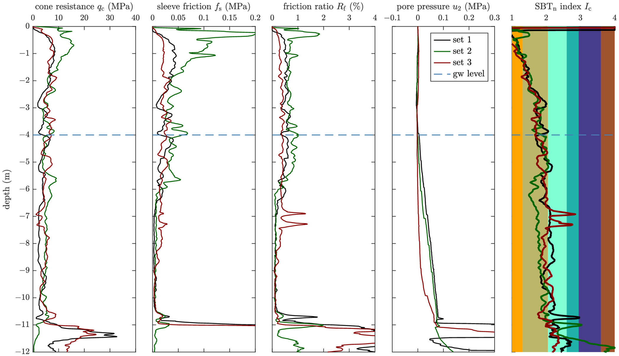
Apart from the near-surface area and the results at a depth of approximately , the CPTu tests show a mostly uniform picture with a soil behavior type of sands and sand mixtures. Therefore, homogeneous subsoil conditions could be assumed for the entire test area. The top of the marine sediments was found at a depth of between and below ground level. Based on the CPTu test results, the compaction depth for all compaction tests was set at a depth of below ground level.
Sequence of the Compaction Tests
The layout for the compaction tests was defined as a triangular grid with a spacing of 3.0 m between the compaction points. A heavy S-series deep vibrator from Keller with a mass of about 4,400 kg was used for all experiments. It creates a centrifugal force of 700 kN in the standard setting and allows for a low- and high-amplitude setting of 14 mm and 35 mm, respectively. The excitation frequency of the vibrator can be set between and , depending on the amplitude setting. The design excitation frequency for this heavy vibrator during compaction is .
During the experimental field tests, the standard operation mode of the vibrator was extensively investigated. The compaction was carried out in a back-step procedure with the high-amplitude setting and excitation frequency of . The flow rate of the jetted water varied between and . Selected experiments were conducted with process parameters deviating from the standard, whereby a variation of different parameters in the highest possible range was achieved. For this paper, the following experiments are of particular interest:
•
Evaluation test with frequency ramps under a pulsating superimposed load.
•
Set 1: compaction with standard excitation frequency ().
•
Set 2: compaction with reduced excitation frequency ().
•
Set 3: compaction with increased excitation frequency ().
Three individual tests with constant parameters were carried out for each of the three excitation frequencies discussed (Fig. 4). The reduced excitation frequency of and the increased excitation frequency of represent the maximum achievable deviations from the standard excitation frequency that could be realized without damaging the vibrator. Note that increasing the excitation frequency by only 3 Hz to 28 Hz still leads to an increase in centrifugal force of 200 kN due to the quadratic excitation.
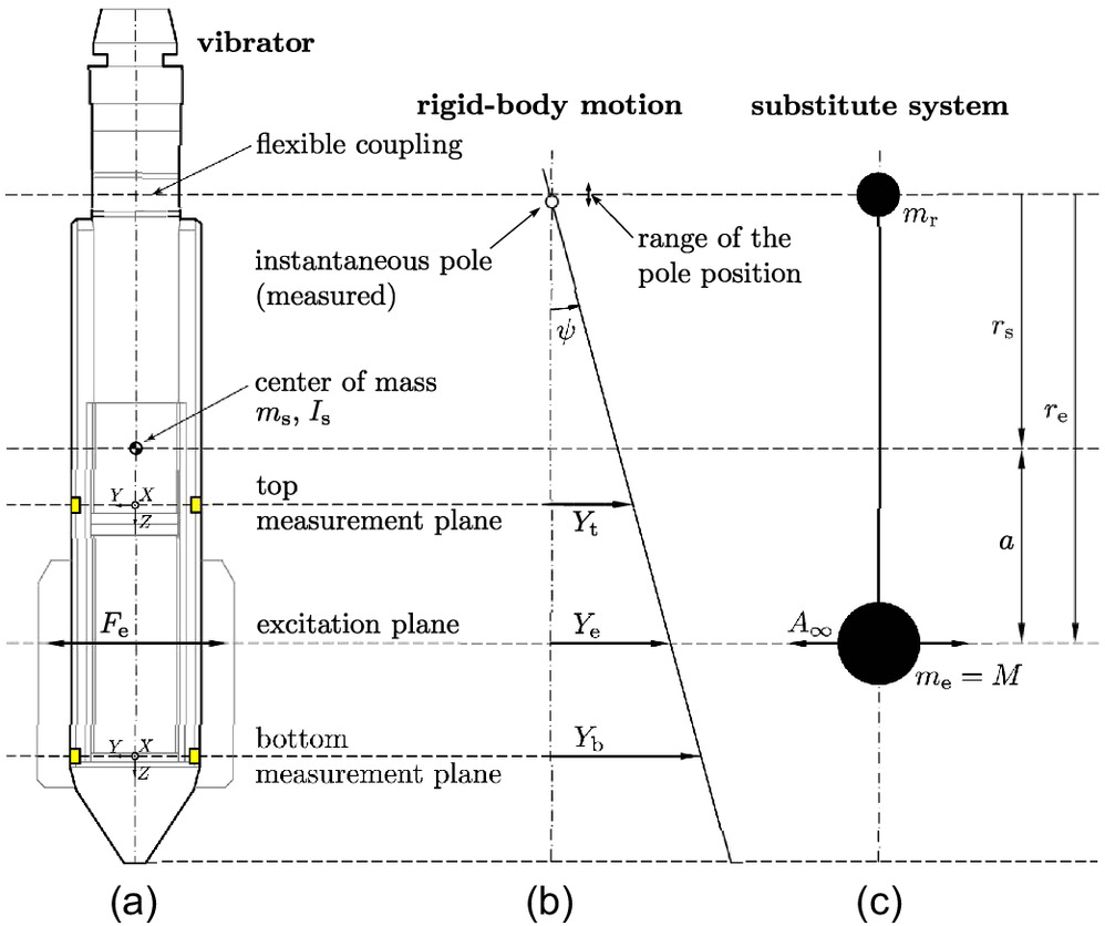
The measuring system consisted mainly of heavy-duty triaxial accelerometers for recording the vibrator movement and pulse emitters for the determination of the current position of the rotating eccentric mass. Two accelerometers were mounted in two measurement levels each, a top measurement level above the eccentric mass and a bottom measurement level below the eccentric mass (Fig. 6).
In addition to the vibrator movement, numerous process parameters were recorded during the compaction tests, such as vibrator frequency, vibrator tip load, vibrator depth, flow rates of the jetted water, and power demand of the electric motor. The results of the extensive experimental field tests are not discussed in detail within this paper. However, selected test results are used for the explanation of the novel concept of vibrocompaction at the natural frequency of the soil response.
Vibrocompaction at the Natural Frequency of the Soil Response
In contrast to the state-of-the-art procedure of aiming for a compaction at the natural frequency of the interaction system, the authors mentioned a new concept in Kopf et al. (2023). This different and novel approach for an optimized compaction is presented in this paper.
The dynamically excited vibrator causes a response of the soil in the form of a resulting soil contact force, denoted by . The soil contact force comprises the entire response of the soil system, including the soil stiffness, radiation damping (both of which might be frequency-dependent and/or nonlinear), as well as a vibrating soil mass. The dynamic properties of the soil are unknown and no attempt is made to describe them, e.g., in the form of a spring stiffness or a dashpot coefficient. It is proposed to calculate the resulting soil contact force and its direction from measurements and directly measure the displacement amplitude of the vibrator and its direction. It is suggested that an angle of between the directions of the soil contact force and the displacement results in the best possible compaction, since it is a compaction at the natural frequency of the soil response. The amplitudes and directions of and will change of course as the soil is compacted.
The applicability of the concept requires fulfillment of the following conditions:
1.
Continuous contact between the vibrator and the soil;
2.
Harmonic loading of the soil;
3.
Admissibility of describing the vibrator movement with a SDOF; and
4.
The soil contact force acting on the vibrator must rotate around the vertical axis of the vibrator.
Given suitable soil conditions, conditions 1, 2, and 4 are considered fulfilled for deep horizontal vibrocompaction. In order to fulfill condition 4, it is assumed that the vibrator performs a rigid-body motion along a cone of rotation, with the tip of the cone located at the flexible coupling. The vibrator movement is therefore described with only an SDOF, the rotation angle of the vibrator along the cone around the vertical axis. The admissibility of this approach is not necessarily obvious, but it is shown in the following that this simplification is permissible at least for the S-series vibrator under investigation in almost all registered motion states.
The formulated prerequisites for the application of the concept limit confirm its transferability to other forms of vibratory compaction. Vibratory roller compaction and vibratory plate compaction, for example, are characterized by the challenging contact conditions between compaction equipment and soil. With the exception of very soft soils, vibratory rollers and plate compactors will periodically or aperiodically loose contact with the soil. Therefore, continuous contact (condition 1) cannot be guaranteed, and the compaction energy is transmitted to the soil in a series of impacts instead of a harmonic loading (condition 2). Deep vertical vibratory compaction is similar to vibroflotation in some aspects, and the resonance behavior of the vibrator-probe-ground system has already been investigated by Massarsch and Fellenius (2005) for this vibratory compaction method. However, the concept of vibrocompaction at the natural frequency of the soil response is not applicable to vertically oscillating probes, as the resulting soil contact force does not rotate around the vertical axis of the probe (condition 4).
Center of Rotation and Center of Impact
If an eccentric impulse with distance to the center of mass is applied to a stationary rigid body with mass and the moment of inertia at the center of mass , the subsequent motion is composed of a translational and a rotational part and a certain point inside or outside the rigid body, the center of impact, remains at rest for the time being (instantaneous pole) and forms the center of rotation. For each eccentric point of impact with distance from the center of mass, there is an associated center of impact on the opposite side of the center of mass with distance from it. The product of these two distances and is constant and equals [Eq. (3)]:
(3)
For each of these related distance pairs, there is a mechanically equivalent substitute system (Fig. 6) consisting of two rigidly connected point masses and , whose sum gives . The position of the common center of mass and the mass moment of inertia remain unchanged and correspond to the original system. However, the approach of the mechanically equivalent system offers the advantage that the reduced equivalent mass at the load application point can be used for the calculations. In the simplified approach chosen here, with only one degree of freedom, the reduced equivalent mass can thus be used directly as the modal mass of the system [Eq. (4)]:where is the distance between the excitation plane and the center of impact. The harmonic excitation of the vibrator in the excitation plane can be viewed as a temporal sequence of individual impacts. As long as the rotation angles remain small (, ), the application of the presented equivalent system and the relations derived from it is admissible.
(4)
The S-series vibrator under investigation is designed in such a way that the center of impact (center of rotation) for the eccentric excitation by the unbalance is located exactly in the flexible coupling, which separates the vibrator from the extension tubes and remains practically at rest when vibrating freely in the air, while the vibrator performs a rotational motion around the vertical axis. Furthermore, the vibrator is designed in such a way that the point of application of the soil contact force during compaction is also approximately on level with the exciter plane, so that the center of rotation determined from the measurements (Fig. 6) deviates within a very small range from the position of the flexible coupling. The design has three decisive advantages: it prevents the flexible coupling from being damaged during compaction work, there are hardly any interfering forces on the compactor from the extension tubes and, moreover, the simplification of considering only one degree of freedom has been proven to be relevant in practice.
For each harmonic force of magnitude acting in the excitation plane of a compactor vibrating freely in the air, there is a proportional, 180° phase-shifted (i.e., opposite), deflection . The amplitude is proportional to the excitation force [Eq. (5)]:
(5)
For a constant excitation force , the amplitude decreases proportionally to an increase of the modal mass , while it decreases with the square of the angular excitation frequency .
The investigated vibrator was equipped with accelerometers in two planes [see Fig. 6(a)]. In addition, the position of the eccentric mass was also measured. Assuming rigid-body motion, the acceleration in the excitation plane can be linearly interpolated with the accelerations of the upper and lower measurement planes. By integration, the velocity and the deflection in the excitation plane are also known. The superposition of the orthogonally measured vibrations represents the circular vibrator motion. Thus, the position and magnitude of the excitation force and the deflection amplitude in the excitation plane are measurable and known, both for the compactor vibrating freely in the air and during compaction and interaction with the soil.
Proof of the Admissibility of the SDOF Approach by Measurement
It is assumed that the vibrator can be sufficiently described as system with only one degree of freedom. Under this assumption, the vibrator performs a rigid-body motion along a cone of rotation, with the tip of the cone located exactly at the flexible coupling between the vibrator and the extension tubes. The admissibility of the approach is proven for the S-series vibrator by means of an experimental evaluation test under a pulsating superimposed load.
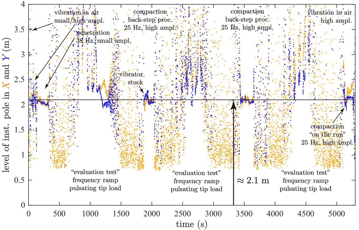
All field tests presented in this paper were conducted prior to the development of the novel concept. The individual tests therefore originally served a different purpose. The test procedure depicted in Fig. 7, for example, was primarily developed for the assessment of surface waves. Fig. 7 shows the process parameters vibrator depth, applied tip load, and excitation frequency, as well as the vibration amplitudes derived from the measured accelerations transverse to the wing direction and in wing direction . The very long and unconventional test procedure is unique in that it covers not only the standard compaction in the back-step procedure but also exceptional operating conditions.
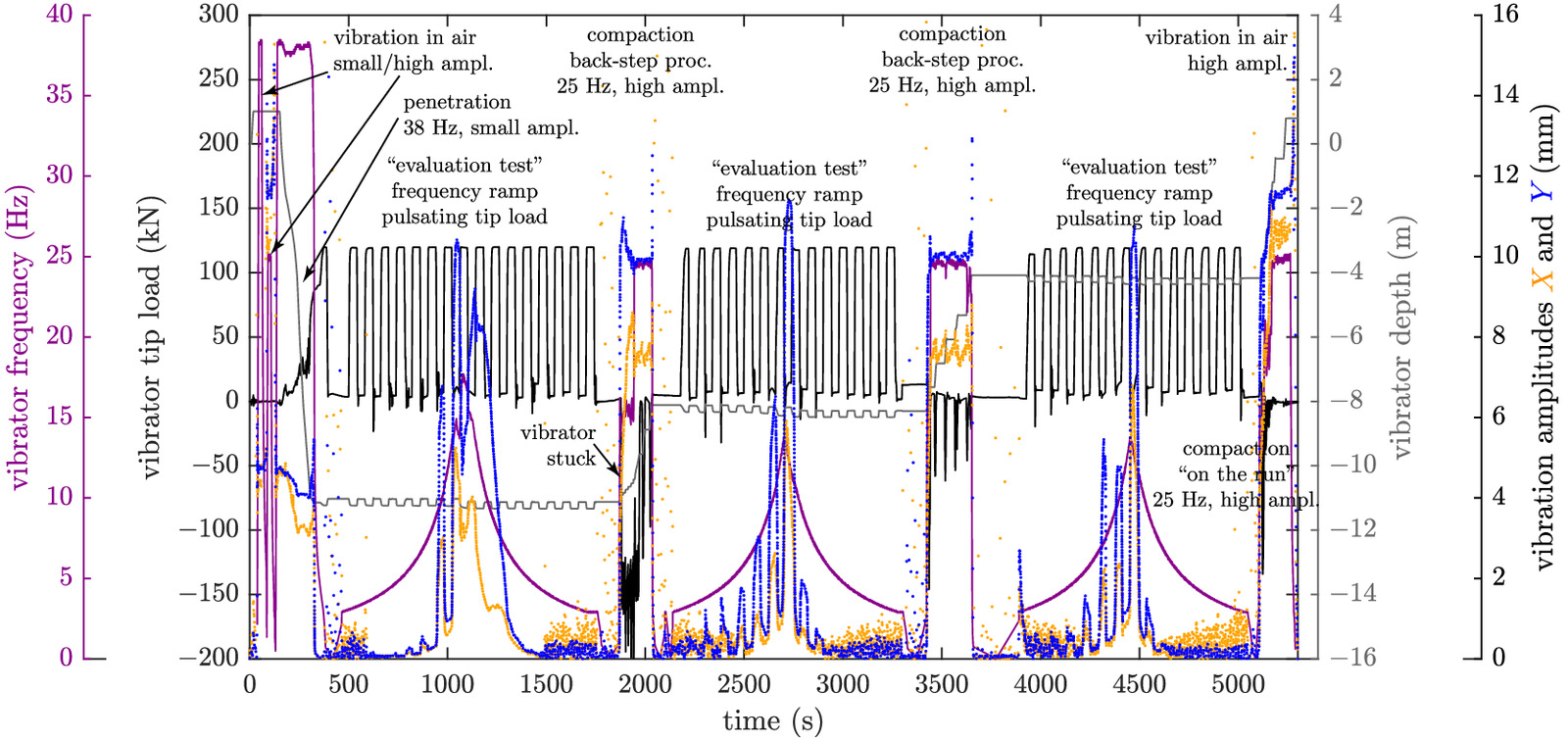
The experiment starts with the vibrator vibrating freely in the air with the small-amplitude setting and an excitation frequency of . The process parameters are then changed to a high-amplitude setting with a frequency of . These frequencies are also used during penetration and compaction in the further course of the test.
After the vibration in the air, the vibrator body is lowered to the desired compaction depth (about ) using the small-amplitude setting and an excitation frequency of . The penetration speed increases below the groundwater table (about below ground level).
At this point, the actual evaluation test begins. With the high-amplitude setting, the excitation frequency is increased by means of a frequency ramp until the vibrator is mobilized. At this moment, the frequency ramp is reversed and according to the same regularity the excitation frequency is reduced again. Superimposed on this procedure, the vibrator is raised with the crane at regular time intervals (black in Fig. 7) exactly with the vibrator weight (no contact pressure between vibrator cone and soil) and then fully lowered again (full tip load). The impact of the excitation frequency and the tip load on the motion behavior of the vibrator can be observed in the vibration amplitudes. Moreover, the vibration amplitudes clearly indicate the mobilization of the vibrator and the reversal of the frequency ramp.
After an idle phase, the vibrator was operated in the standard operation mode (high amplitude, ) in the back-step procedure to a depth of approximately . It is remarkable that the vibrator got stuck during the evaluation test in such a way that the crane had to initially pull even 2.5 times the vibrator weight in order to mobilize and pull up the stuck vibrator. The vibrator was also hindered in its dynamic motion behavior.
The compaction process was paused at a depth of about in order to perform a second evaluation test with a pulsating superimposed load. Based on the vibration amplitudes, the periodic mobilization of the vibrator by contact pressure relief (lifting) and the subsequent obstruction of the dynamic movement by loading the vibrator tip with the full vibrator weight (“overpressing”) can be observed. After another idle phase, the vibrator was operated in the standard operation mode in the back-step procedure up to a depth of about to perform a third evaluation test.
During the subsequent step-wise pulling in the standard operation mode, the vibrator is already above the groundwater. In order not to exceed the power and temperature limit, which is harmful to the unit, the motor is automatically regulated back, whereby the frequency is reduced below the initial and the vibrator is pulled faster. Once the vibrator has left the ground, it vibrates freely in the air with the high-amplitude setting and an excitation frequency of .
The sketch in the center of Fig. 6 illustrates the determination of the level of the instantaneous pole in regard to the excitation plane. It is based on the acceleration measurements in the top and bottom measurement plane under the assumption of a rigid body motion. The existence and stable position of this pole depend on the fulfillment of the following requirements:
•
The signals of the sensors in the top and bottom plane must be either in phase (phase lag = 0°) or exactly counter phase (phase lag = 180°). Otherwise, the axis of the vibrator body describes a rotational hyperboloid, which has no point at rest and, therefore, the instantaneous pole does not exist.
•
The amplitude ratio between the signals of the top and bottom level sensors must be constant. Otherwise, a pole may exist (first condition), but its vertical position would change cyclically.
In addition to the process parameters of the vibroflotation, Fig. 8 shows the vibration amplitudes calculated by a double integration of the accelerations measured during the test procedure presented in Fig. 7. The amplitudes in the - and -directions of each measurement plane are plotted in a complex representation where the absolute value of the imaginary number corresponds to the amplitude (norm of the vectorially composed components in the - and -directions) and the phase is the phase angle.
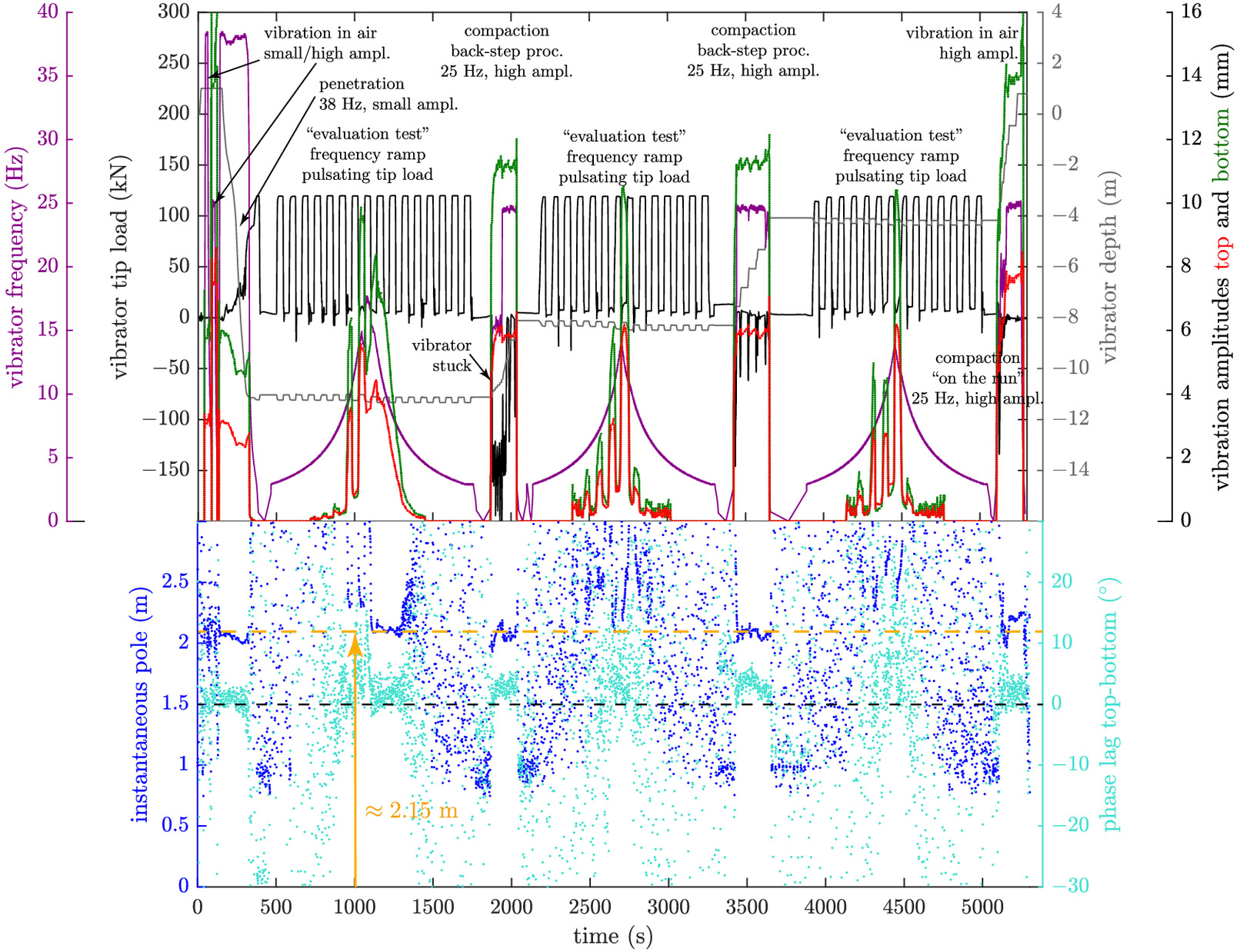
The level of the instantaneous pole above the excitation plane is calculated from the mean amplitudes of the top and bottom measurement plane according to Fig. 6. However, the calculated value is only valid if the phase lag is close to zero (as explained above). It is nearly impossible for the phase lag to become exactly zero due to the gyroscopic forces of the rotating masses (eccentric masses, shafts, armatures of the motor) that cause a slight torque-induced precession (change in the orientation of the rotational axis of a rotating body when an external force exerts a torque perpendicular to this axis). Due to the minimal phase lag, this phenomenon is not further investigated.
The results presented in the lower part of Fig. 8 clearly illustrate that whenever the vibrator is sufficiently mobile, the instantaneous pole is at an approximately constant distance () above the excitation plane. This applies to the phases of the vibrator vibrating freely in the air, penetration, during the back-step procedure both in the compaction phase and during pulling (even if the vibrator is stuck and cannot be pulled) and also above the groundwater table when the vibrator is on the run.
When the instantaneous pole of the vibrator is at this constant level, the phase lag also stabilizes at approximately 0°. However, it is just as important to see that the vibrator often does not have a stable instantaneous pole during the evaluation test. It is the empirical proof that the vibrator motion is not forced into this mode by the flexible coupling between the vibrator body and the extension tubes. Rather, the vibrator can very well move in other vibration modes (with a distinct phase lag ) in conjunction with the extension tubes. The vibrator voluntarily vibrates in the desired mode (as soon as it is sufficiently mobile) with a stable instantaneous pole only because of the well-balanced design (Fig. 6). The pole is located in the flexible coupling (center of impact) and the extension tubes remain at rest.
This at the same time also the proves that no relevant dynamic forces (holding forces) are transmitted from the extension tubes into the vibrator. Thus, the differences of the measured vibrator motion in the air and during compaction in the soil are exclusively due to the dynamic soil contact forces, which will be investigated in more detail within the scope of this paper.
The design of the vibrator with its wings causes different bedding conditions in the - and -directions. Therefore, the cone of vibration moves along an elliptical path. In Fig. 9, the level of the instantaneous pole is shown separately for both directions of the horizontal motion (different amplitudes and phases). The evaluation illustrates that the constant level of the instantaneous pole is given for both directions. At the end of the first evaluation test, it can be seen that due to the higher bedding in the -direction (transverse to the wing direction), the mobility in this direction is limited earlier than in the wing direction (y-direction). Thus, the level of the instantaneous pole deviates from the constant value.
The dynamically balanced design of the investigated vibrator in Fig. 6 guarantees a stable level of the instantaneous pole coinciding with the flexible coupling only for the vibrator vibrating freely in the air. The fact that the vibrator, as a compaction device in the soil, retains the stable level of the instantaneous pole is due to its shape, which in combination with the dynamic vibration mode and the contact conditions apparently produces a resultant soil reaction force that acts sufficiently accurately in the excitation plane of the unbalance and thus does not cause any significant displacement of the pole or its disappearance. Therefore, the last required condition is fulfilled to describe the investigated vibrator with sufficient accuracy as a system with only one degree of freedom and to represent the dynamic system by the equilibrium of forces (momentum theorem) in the excitation plane.
Force-Displacement Relation in the Excitation Plane
Mass and eccentricity of the unbalance are known for the given vibrator. The measurement of the position of the eccentric mass enables the calculation of the angular excitation frequency and, therefore, the magnitude [according to Eq. (2)] and direction of the excitation force . The measurement of the associated displacement of the vibrator vibrating freely in the air allows for a determination of the modal mass , according to Eq. (5), and a calibration of the phase angle (lead angle) to 180°.
The dimensionless representation in Fig. 10 illustrates the procedure for the determination of the unknown soil contact force . The considerations are based on the relationships given in Eq. (6):
(6)
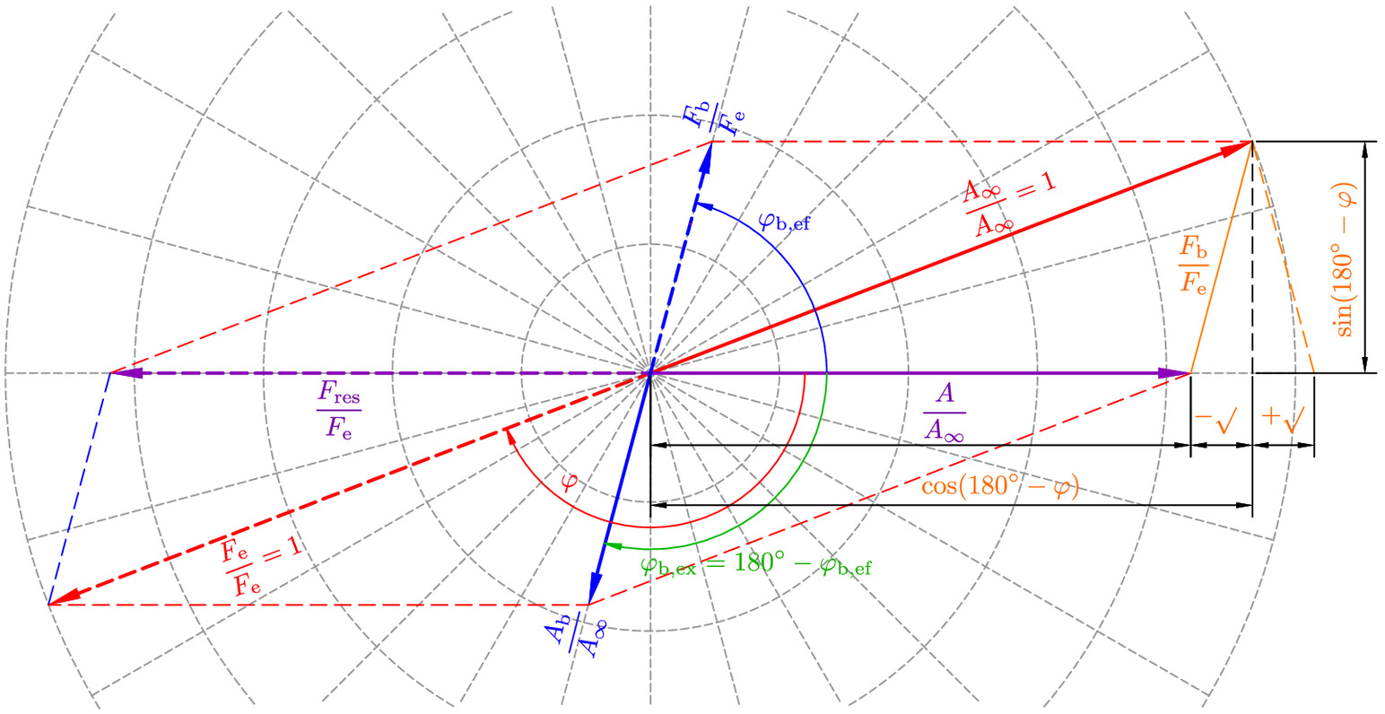
All forces (dashed vectors) are normalized to the excitation force . The corresponding displacements are normalized to the displacement of the vibrator vibrating freely in the air and plotted in the opposite direction according to mechanical principles. In the example shown, the displacement derived from measurements during compaction is shown from the center to the right. The corresponding resulting force is plotted with the same length (in the normalized diagram), but in the opposite direction. It is composed of the known excitation force (dashed vector under the measured lead angle , pointing to the bottom left) and the normalized soil contact force to be determined (dashed vector under the trailing angle , also to be determined, pointing to the top right). Thus, the determination of the soil contact force and its trailing angle with respect to the measured vibrator displacement is limited to a vector addition each [Eqs. (7) and (8)]:
(7)
(8)
A compaction at the natural frequency of the soil response is given for a trailing angle of . According to the action-reaction principle, the soil contact force acts on the vibrator, while a force of the same magnitude acts in the opposite direction as excitation on the soil. Therefore, the trailing angle (restraining for the vibrator) and the leading angle (driving for the soil) complement each other to 180°.
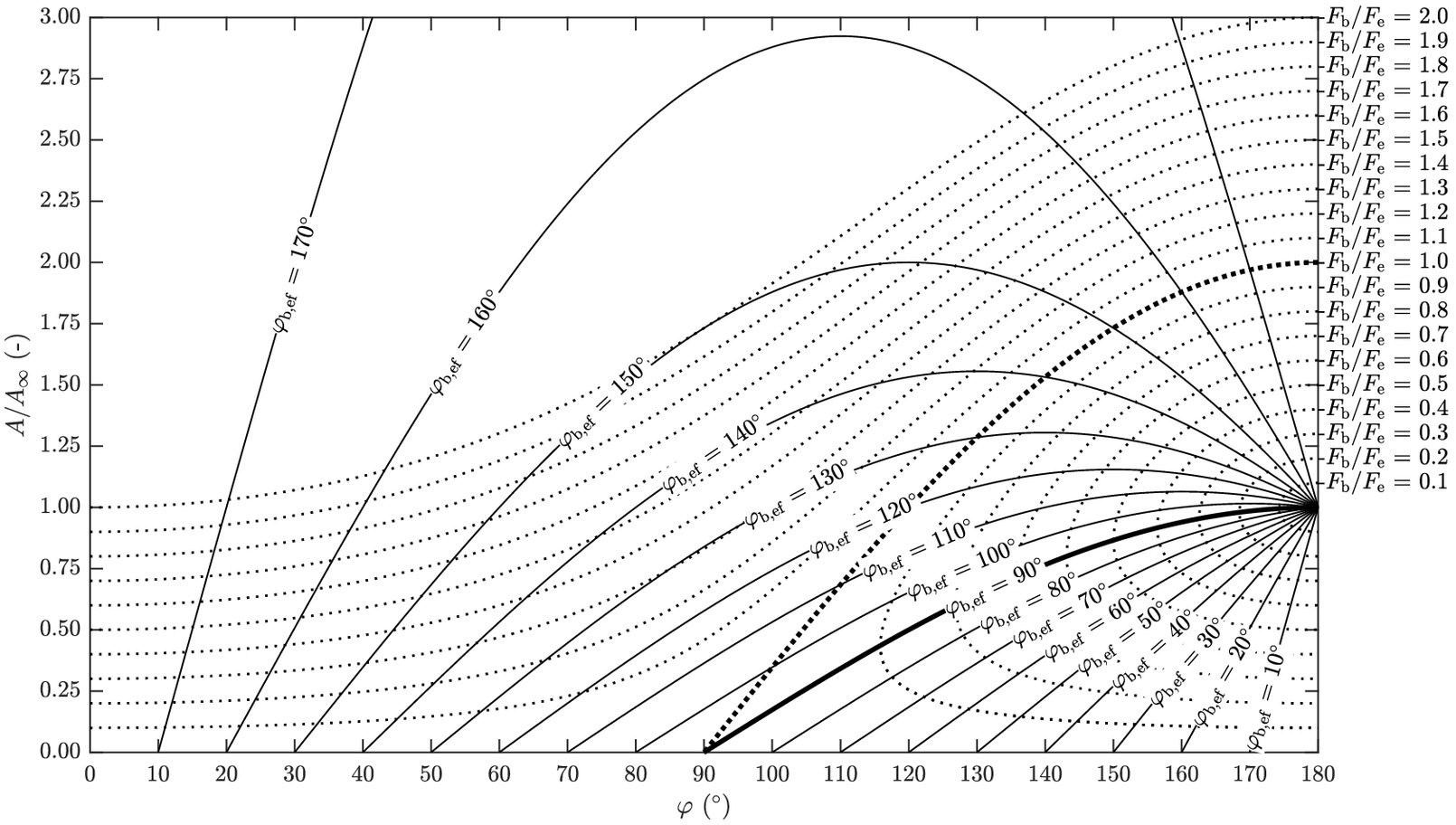
The representation in Fig. 10 can also be used to plot the normalized amplitude of the displacement over the lead angle for a variation of the normalized soil contact force and the trailing angle , respectively. The corresponding equations for the calculation of are given in Eqs. (9) and (10):
(9)
(10)
In Fig. 11, Eqs. (9) and (10) are evaluated for a normalized soil contact force ranging from 0.1 to 2.0 and a trailing angle ranging from 0° to 180°. Both the amplitude ratio and the lead angle can be measured. The diagram in Fig. 11 therefore allows a quick determination of the unknown soil contact force and the trailing angle .
Application of the Presented Concept to Measurement Data
The presented concept proposes to calculate the resulting soil contact force and its direction from measurements and directly measure the displacement amplitude of the vibrator and its direction. It is suggested to strive for an angle of between the directions of the soil contact force and the displacement to optimize the densification process.
It has not yet been possible to apply the proposed concept in specially designed experimental studies. The concept is therefore tested using selected measurement data from the experimental field tests that were carried out in 2019 before the methodology presented was developed.
The amplitude and the lead angle were recorded during the field tests and are evaluated for a variation of the excitation frequency. In addition to the standard excitation frequency of , a reduced frequency of and an increased frequency of were tested. Three compaction tests were performed for each of the frequency variants (Fig. 4).
The amplitude ratio is plotted over the lead angle in Fig. 12 for seven compaction steps at depths of –10 m to –5 m. The results are shown for both horizontal vibrator directions ( = transverse to wing direction and = in wing direction) and each of the three excitation frequencies. The results in Fig. 12 confirm that a lead angle of (left edge of the diagram), as suggested in the literature, is far from being achieved in practice. Detailed representations are given in Fig. 13 for the -direction (transverse to wing direction), and in Fig. 14 for the -direction (in wing direction), respectively. The geometry of the vibrator in its setup utilized for the tests with wings in the -direction causes different bedding conditions in the two horizontal directions and thus a direction-dependent motion behavior of the vibrator.
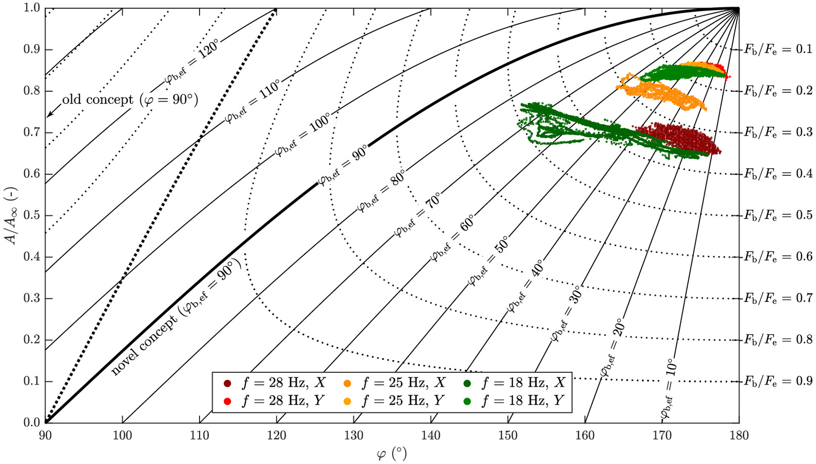
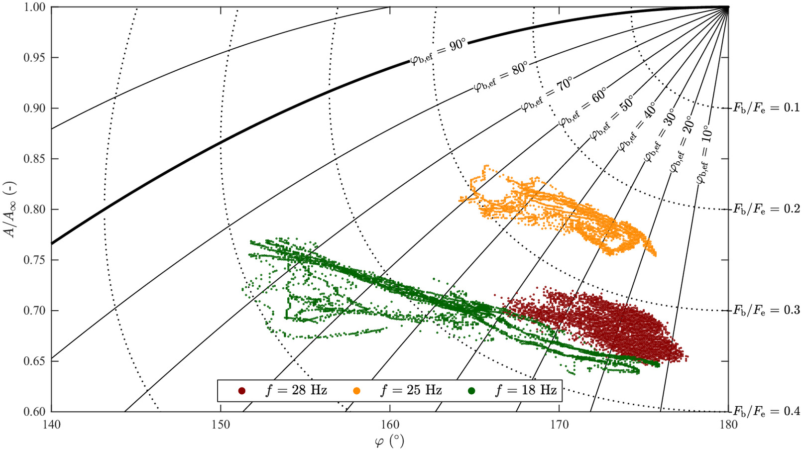
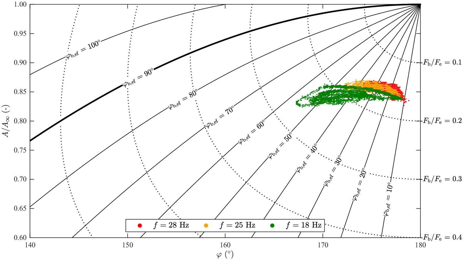
The vibrator motion only shows a small variability transverse to the wing direction () in case of the high excitation frequency of (Figs. 12 and 13). The high amplitude of the excitation force dominates the vibrator motion and the influence of the soil is minimal. In contrast, the amplitude ratios of the low excitation frequency of show higher variability. They cover a large range of the trailing angle of the soil contact force and even get fairly close to the natural frequency of the soil response at .
The increased excitation frequency of leads to a significantly larger amplitude of the excitation force of (Table 1). However, only about a third of it is utilized as soil contact force (Fig. 13). The amplitude of the excitation force is significantly smaller for the reduced frequency of (, see Table 1), but it is used much more efficiently and about half of it is utilized as soil contact force. An increased flow rate of the jetted water at the cone ( instead of ) was required to operate the vibrator at the increased frequency of without exceeding the power and temperature limit of the vibrator.
| Frequency, (Hz) | Force, (kN) | Electrical energy (MJ) | Flow ratea () | Duration (min) |
|---|---|---|---|---|
| 28 | 24.1 | 200 | 5.6 | |
| 25 | 18.6 | 150 | 4.5 | |
| 18 | 11.8 | 150 | 3.7 |
a
The flow rate is of the jetted water at the cone.
The compaction success was monitored with CPTu tests. The tests were carried out 18 to 21 days after treatment at the centers of the triangular grid of the compaction tests with the same vibration frequencies (Fig. 4). A full set of CPTu results for the three locations after treatment in comparison with the results obtained prior to treatment is given in Fig. 15. With exception of the near-surface area, cone resistance and sleeve friction were low in the sand fill but increased after treatment by vibrocompaction. The degree of improvement is approximately the same below the groundwater table for the cone resistance and the sleeve friction, whereby the mean values after treatment are around five times higher than before compaction. Compaction with an excitation frequency of tended to lead to the highest absolute values of cone resistance, while pronounced sleeve friction values were recorded after treatment with . With only one CPTu test per parameter set, the differences in the CPTu results after compaction cannot be attributed exclusively to the different excitation frequencies, as these also depend on the local initial conditions. However, it is noteworthy that compaction with a reduced excitation frequency leads to densification results below the groundwater table that are at least on par with the results after treatment with higher frequencies.
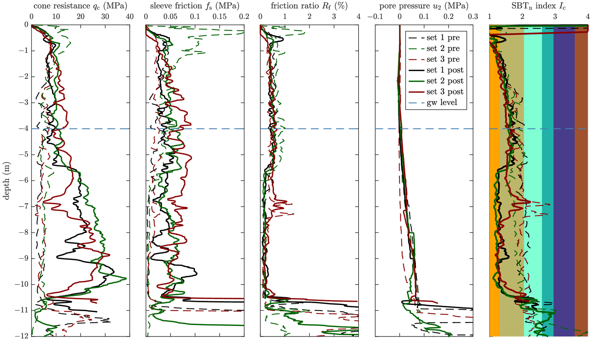
The CPTu results above the groundwater table cannot be directly attributed to the different excitation frequencies and must be viewed with caution. In order not to exceed the power and temperature limit of the vibrator, which is harmful to the unit, the motor was automatically regulated back above the groundwater table, whereby the frequency was reduced below the initial setting and the vibrator had to be pulled faster.
In Table 1, additional parameters of the compaction tests are listed. The compaction with the reduced frequency of required less than half the electrical energy, a shorter period of time, and less jetted water, but still achieved compaction results on par with the results after compaction with an increased frequency of (Fig. 15). The differences in electrical energy demand and required compaction time are less pronounced when comparing the results for compaction with to the standard, but are still in favor of the reduced excitation frequency. It is assumed that the increased electrical energy demand required for compaction at high excitation frequencies, but which does not lead to an improvement in compaction success, merely results in increased machine wear.
The good compaction results after treatment with a reduced excitation frequency despite the significantly reduced amplitude of the excitation force are attributed to the large variability of the trailing angle and the compaction closer to the natural frequency of the soil response. For practical application in vibrocompaction projects, it is therefore recommended to adapt the process parameters of the vibrator to the conditions found on site and not to rely solely on the theoretical amplitude of the excitation force .
Conclusions
The state of research suggests that the best possible compaction results in deep horizontal vibrocompaction are achieved when the vibrator operates at the natural frequency of the vibrator-soil interaction system (lead angle ). In the scope of a previous research project, a vibrator was specially equipped with sensors to allow a lead angle controlled compaction. The compaction results were not satisfactory and the state of research concept proved to be unsustainable in practical application. This finding led to the research presented in this paper and the development of the concept of compaction at the natural frequency of the soil response.
The presented concept suggests to calculate the resulting soil contact force and its direction from measurements and directly measure the displacement amplitude of the vibrator and its direction. It is proposed that an angle of between the directions of the soil contact force and the displacement amplitude results in an optimized compaction. The applicability of the concept requires continuous contact between the vibrator and the soil, a harmonic loading of the soil, the admissibility of describing the vibrator movement with a SDOF, and the soil contact force to rotate around the vertical axis of the vibrator.
It was shown on the example of measurement data that the simplified approach of describing the vibrator movement with only a SDOF is permissible at least for the vibrator under the investigated conditions. A procedure for the determination of the unknown soil contact force and the trailing angle was shown by means of the force-displacement relation in the excitation plane. Compaction at the natural frequency of the soil response is given for a trailing angle of . The introduced equations and the diagram in Fig. 11 allow a quick determination of the soil contact force and the trailing angle based on measurements of the vibration amplitude and the lead angle during compaction.
The method for determining the soil contact force and the trailing angle was applied to measurement data from compaction tests as part of a land reclamation project in Southeast Asia, which were carried out in 2019 before the concept was developed. Tests with three different excitation frequencies were investigated. CPTu tests were conducted at selected points of the triangular compaction grid before treatment and at the center points of the grid after compaction to monitor compaction success.
The main findings of the research for the practical application of deep horizontal vibrocompaction are as follows:
•
Provided that the vibrator movement can be described with a SDOF, it is possible to determine the soil contact force and its direction directly.
•
The soil contact force comprises the entire response of the soil system, including the soil stiffness, radiation damping, and a vibrating soil mass. The soil contact force and its direction therefore change with increasing densification.
•
The presented concept can be easily extended to also cover soil contact forces acting out of the excitation plane if practical application should show the need. However, for this case the clearness of the method is lost.
•
The application of the concept to measurement data shows a small variability of the vibrator motion for an increased excitation frequency of . The significantly larger excitation force amplitude of this setting dominates the vibrator motion. However, only about a third of the excitation force is utilized as soil contact force. The increased excitation frequency did not lead to better compaction results, and the increased energy demand is expected to cause increased machine wear.
•
The amplitude ratios of the reduced excitation frequency of cover a broad range of the trailing angle. The vibrator is able to work close to the natural frequency of the soil response (), which leads to a pronounced compaction effect. The amplitude of the excitation force is significantly smaller compared to the high-frequency setting, but it is utilized much more efficiently. The CPTu results were at least on par with the results after treatment with higher frequencies. The compaction with the reduced frequency required less than half the electrical energy, a shorter period of time, and less jetted water.
•
The findings of this study indicate that there is no direct correlation between the applied excitation force and the compaction effect. The efficiency of compaction rather depends on the shear strain amplitude generated as a result of the trailing angle.
•
The reduction of the excitation frequency in practical application requires a reasonable limit. Due to the quadratic excitation, the amplitude of the excitation force decreases significantly with decreasing excitation frequency and soon becomes ineffective.
•
The approximation to the natural frequency of the soil response can be a valuable criterion for the identification of this limit and thus contributes to an optimization of the deep vibrocompaction process.
•
The previous state of research seems to be outdated. Under realistic conditions, a lead angle of (left edge in Fig. 12) is only achieved at the time of mobilization of the vibrator, but not in an operating condition that allows efficient compaction.
•
Future research could implement a compaction at the natural frequency of the soil response by continuously adapting the process parameters excitation frequency, applied tip load, and jetted water to achieve a trailing angle close to .
•
The application of the concept to other vibrators requires a review of the admissibility of the SDOF approach by measurement. Such measurements and the application of the concept presented require the vibrator to be instrumented with accelerometers as well as pulse emitters for the determination of the current position of the rotating mass.
Notation
The following symbols are used in this paper:
- vibrator amplitude (m);
- amplitude of free vibration in air (m);
- damping ratio;
- eccentricity of unbalance (m);
- soil contact force (N);
- excitation force (N);
- excitation frequency (Hz);
- moment of inertia of vibrator ();
- modal mass (kg);
- mass of unbalance (kg);
- reduced equivalent mass (kg);
- point mass (kg);
- mass of vibrator (kg);
- cone resistance (Pa);
- distance from excitation plane to center of impact (m);
- distance from center of mass to center of impact (m);
- amplification factor;
- frequency ratio;
- lead angle (phase angle) (degrees);
- trailing angle of soil response (degrees);
- leading angle of soil response (degrees);
- rotation angle (degrees);
- angular excitation frequency (); and
- natural angular frequency ().
Data Availability Statement
All data, models, and code generated or used during the study appear in the published article.
References
Arnold, M., and I. Herle. 2009. “Comparison of vibrocompaction methods by numerical simulations.” Int. J. Numer. Anal. Methods Geomech. 33 (16): 1823–1838. https://doi.org/10.1002/nag.798.
Bałachowski, L., and N. Kurek. 2015. “Vibroflotation control of sandy soils using DMT and CPTU.” In Proc., 3rd Int. Conf. on the Flat Dilatometer. Rome: Marchetti Dilatometer.
Bitri, A., K. Samyn, S. Brûlé, and E. Javelaud. 2013. “Assessment of ground compaction using multi-channel analysis of surface wave data and cone penetration tests.” Near Surf. Geophys. 11 (6): 683–690. https://doi.org/10.3997/1873-0604.2013037.
Bo, M. W., M.-F. Chang, A. Arulrajah, and V. Choa. 2012. “Ground investigations for Changi East reclamation projects.” Geotech. Geol. Eng. 30 (1): 45–62. https://doi.org/10.1007/s10706-011-9448-3.
Brumund, W. F., and G. A. Leonards. 1972. “Subsidence of sand due to surface vibration.” J. Soil Mech. Found. Div. 98 (1): 27–42. https://doi.org/10.1061/JSFEAQ.0001731.
Chopra, A. K. 2007. “Dynamics of structures: Theory and applications to earthquake engineering.” In Prentice-Hall international series in civil engineering and engineering mechanics, 72–85. Upper Saddle River, NJ: Prentice Hall.
Covil, C. S., M. C. W. Luk, and A. R. Pickles. 1997. “Case history: Ground treatment of the sandfill at the new airport at Chek Lap Kok, Hong Kong.” In Proc., Conf. Ground Improvement Geosystems Densification and Reinforcement, 148–156. London: Thomas Telford.
D’Appolonia, E. 1953. “Loose sands: Their compaction by vibroflotation.” In Proc., Symp. on Dynamic Testing of Soils, 138–162. West Conshohocken, PA: ASTM.
Das, B. M., and Z. Luo. 2016. Principles of soil dynamics. Boston, MA: Cengage Learning.
Fellin, W. 2000. Rütteldruckverdichtung Als Plastodynamisches problem. London: CRC Press.
Fellin, W., G. Hochenwarter, and A. Geiß. 2003. “Großversuche zur Entwicklung eines Qualitätssicherungssystems für die Rütteldruckverdichtung.” Bauingenieur 78 (9): 433–439.
Karray, M., G. Lefebvre, Y. Ethier, and A. Bigras. 2010. “Assessment of deep compaction of the Péribonka dam foundation using ‘modal analysis of surface waves’ (MASW).” Can. Geotech. J. 47 (3): 312–326. https://doi.org/10.1139/T09-108.
Kim, D. S., and H. C. Park. 1999. “Evaluation of ground densification using spectral analysis of surface waves (SASW) and resonant column (RC) tests.” Can. Geotech. J. 36 (2): 291–299. https://doi.org/10.1139/t98-103.
Kirsch, K., and F. Kirsch. 2017. Ground improvement by deep vibratory methods. London: Taylor & Francis.
Kopf, F., C. Kummerer, D. Adam, and J. Pistrol. 2023. “Tiefenrüttler–optimale verdichtung in eigenfrequenz der bodenkontaktkraft.” In Vol 16 of Beiträge zum 37 Christian Veder Kolloquium, 297–316. Graz, Austria: Technische Universität Graz.
Massarsch, K. R. 2023. “Applications of deep vertical vibratory compaction.” In Proc., 5th Int. Conf. on Geotechnics for Sustainable Infrastructure Development. Berlin: Springer.
Massarsch, K. R., and B. H. Fellenius. 2002. “Vibratory compaction of coarse-grained soils.” Can. Geotech. J. 39 (3): 695–709. https://doi.org/10.1139/t02-006.
Massarsch, K. R., C. Wersäll, and B. H. Fellenius. 2020. “Horizontal stress increase induced by deep vibratory compaction.” Proc. Inst. Civ. Eng. Geotech. Eng. 173 (3): 228–253. https://doi.org/10.1680/jgeen.19.00040.
Massarsch, R. K., and B. H. Fellenius. 2005. “Deep vibratory compaction of granular soils.” In Vol. 3 of Ground improvement—Case histories, edited by B. Indraratna and J. Chu, 539–561. Amsterdam, Netherlands: Elsevier.
Mitchell, J. K., and Z. V. Solymar. 1984. “Time-dependent strength gain in freshly deposited or densified sand.” J. Geotech. Eng. 110 (11): 1559–1576. https://doi.org/10.1061/(ASCE)0733-9410(1984)110:11(1559).
Morgan, J. G. D., and G. H. Thomson. 1983. “Instrumentation methods for control of ground density in deep vibrocompaction.” In Proc., 8th European Conf. on Soil Mechanics and Foundation Engineering, 59–64. Amsterdam, Netherlands: A.A. Balkema.
Nagula, S., and J. Grabe. 2017. “2-Phase dynamic simulation of deep sand compaction to reduce liquefaction.” Procedia Eng. 199 (Jan): 2396–2401. https://doi.org/10.1016/j.proeng.2017.09.277.
Nagula, S. S., and J. Grabe. 2020. “Coupled Eulerian Lagrangian based numerical modelling of vibro-compaction with model vibrator.” Comput. Geotech. 123 (Jul): 103545. https://doi.org/10.1016/j.compgeo.2020.103545.
Nagy, P. 2018. “Rütteldruckverdichtung: Dynamische Verdichtungskontrolle auf Basis der Rüttlerbewegung.” Ph.D. thesis, Dept. of Civil Engineering, TU Wien.
Nagy, P., J. Pistrol, F. Kopf, and D. Adam. 2021. “Integrated compaction control based on the motion behavior of a deep vibrator.” Transp. Geotech. 28 (Apr): 100539. https://doi.org/10.1016/j.trgeo.2021.100539.
Nendza, M. 2006. “Untersuchungen zu den Mechanismen der dynamischen Bodenverdichtung bei Anwendung des Rütteldruckverfahrens.” Ph.D. thesis, Dept. of Architecture, Civil Engineering and Environmental Sciences, Technische Universität Braunschweig.
Poteur, M. 1968. “Beitrag zur Untersuchung von Böden unter dem Einfluß von Tauchrüttlern.” Ph.D. thesis, Dept. of Civil Engineering, Technische Hochschule München.
Poteur, M. 1971. “Beitrag zur Tauchrüttelung in rolligen Böden.” Baumaschine und Bautechnik 18 (7): 303–309.
Robertson, P. K. 1990. “Soil classification using the cone penetration test.” Can. Geotech. J. 27 (1): 151–158. https://doi.org/10.1139/t90-014.
Robertson, P. K. 2006. “Suggested QC criteria for deep compaction using the CPT.” In Proc., 5th Int. Conf. on Geotechnical and Geophysical Site Characterisation, 711–715. Sydney, Australia: Australian Geomechanics Society.
Seed, H. B., and M. L. Silver. 1972. “Settlement of dry sands during earthquakes.” J. Soil Mech. Found. Div. 98 (4): 381–397. https://doi.org/10.1061/JSFEAQ.0001745.
Studer, J. A., M. G. Koller, and J. Laue. 2008. Bodendynamik: Grundlagen, Kennziffern, Probleme und Lösungsansätze. Berlin: Springer.
Thorburn, S. 1975. “Building structures supported by stabilized ground.” Géotechnique 25 (1): 83–94. https://doi.org/10.1680/geot.1975.25.1.83.
Triantafyllidis, T., and I. Kimmig. 2019. “A simplified model for vibro compaction of granular soils.” Soil Dyn. Earthquake Eng. 122 (Apr): 261–273. https://doi.org/10.1016/j.soildyn.2018.12.008.
Wehr, J. 2005. “Variation der Frequenz von Tiefenrüttlern zur Optimierung der Rütteldruckverdichtung.” In Mitteilungen des Fachgebiets Grundbau und Bodenmechanik, 67–77. Berlin: Technische Universität Berlin.
Wehr, J., and W. Sondermann. 2012. “Deep vibro techniques.” In Ground improvement, edited by K. Kirsch and A. Bell, 57–92. London: CRC Press.
Wotzlaw, M., D. Aubram, and F. Rackwitz. 2023. “Numerical analysis of deep vibrocompaction at small and full scale.” Comput. Geotech. 157 (May): 105321. https://doi.org/10.1016/j.compgeo.2023.105321.
Youd, T. L. 1972. “Compaction of sands by repeated shear straining.” J. Soil Mech. Found. Div. 98 (7): 709–725. https://doi.org/10.1061/JSFEAQ.0001762.
Information & Authors
Information
Published In

Journal of Geotechnical and Geoenvironmental Engineering
Volume 150 • Issue 9 • September 2024
Copyright
This work is made available under the terms of the Creative Commons Attribution 4.0 International license, https://creativecommons.org/licenses/by/4.0/.
History
Received: Oct 5, 2023
Accepted: Apr 18, 2024
Published online: Jul 1, 2024
Published in print: Sep 1, 2024
Discussion open until: Dec 1, 2024
Authors
Metrics & Citations
Metrics
Citations
Download citation
If you have the appropriate software installed, you can download article citation data to the citation manager of your choice. Simply select your manager software from the list below and click Download.