Wave-Induced Liquefaction and Stability of Suction Bucket Foundation in Drum Centrifuge
Publication: Journal of Geotechnical and Geoenvironmental Engineering
Volume 149, Issue 4
Abstract
This paper discusses the instability of suction bucket foundations that are growing in importance for bottom-mounted offshore wind turbines in association with wave-induced liquefaction of sand beds. The instability of suction bucket foundations should be understood in light of fluid–soil–structure interactions. In this study, we investigated the instability using centrifuge wave testing in a drum channel with viscous scaling to match the time-scaling laws for fluid wave propagation and consolidation of the soil. This paper highlights the effects of loosening and heaving of the sand inside the bucket during the installation process, which is one of the onsite problems, on the overall stability and clarifies the stability of the whole system in light of wave–soil–structure interactions. The experimental results showed that the instability of the suction bucket is ascribed to the occurrence and progress of liquefaction of the sand bed around the bucket. The experimental results further demonstrated the effect of embedment of the bucket in a dense layer. An embedded depth of the bucket tip equal to one-third of the bucket skirt length prevented instability of the foundation, despite the spread of liquefaction in the loose sand bed. Even when the dense sand inside and underneath the bucket was loosened during the installation process, the foundation bucket remained stable against severe wave actions. The present study examined and summarized the overall stability of suction bucket foundations in sand beds under severe wave loading and clarified the importance of the progress of liquefaction around the foundations.
Introduction
Wave-induced instability of foundations for offshore wind turbines is becoming an increasingly important research subject with the increasing number of offshore wind farms for achieving future renewable energy goals and reducing carbon dioxide emissions. Suction bucket foundations are growing in importance for bottom-mounted offshore wind turbines (Houlsby and Byrne 2005; OWA 2019). The characteristics of soil–structure interactions on suction type foundations during installation or under external loading have been investigated with centrifuge modeling (Bienen et al. 2018a, b; Zhu et al. 2019), as well as in model tests (Zhu et al. 2018). However, these previous model tests did not deal with wave forces directly, and therefore wave–soil–structure interactions involving the wave-induced instability of seabed soils around a suction foundation have not been directly dealt with in past studies.
Concerning the wave–soil–structure interactions, the wave-induced instability of seabed soils around foundations, such as scour and liquefaction, is an important research subject and has been studied in the laboratory. Scour properties around a suction bucket foundation were observed in flume tests (Stroescu and Frigaard 2016), and the effects of scour on the stability of bucket foundations were investigated in flume tests (Chen et al. 2018). It seems, however, that there have been few studies that have focused on wave-induced buildup of residual pore pressures and liquefaction of seabed soil around a suction type foundation. Miyamoto et al. (2021b) observed the instability of suction bucket foundations due to wave-induced liquefaction in sand beds in a set of centrifuge wave tests, and they reported the relation between the wave-induced liquefaction and the instability of the suction bucket foundations.
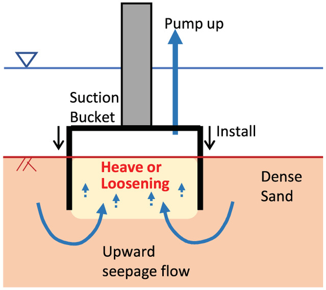
Wave-induced liquefaction may readily occur in loose deposits of sand or silt (Sassa and Sekiguchi 1999, 2001; Sumer and Fredsøe 2002; Sassa et al. 2006; Sumer 2014). The liquefaction around marine structures such as buried pipes, monopiles, and submerged rubble mounds under wave loading has been demonstrated in experiments (Miyamoto et al. 2020, 2021a; Ito et al. 2021). Some relevant case histories and damage caused by wave-induced liquefaction have been reported in the literature (Sumer and Fredsøe 2002; Sassa et al. 2006; Sumer 2014; Sassa 2016; Miyamoto et al. 2020). In the case where a suction bucket foundation is installed in a loose sand bed, liquefaction could occur around the foundation under severe waves, leading to collapse of the foundation. In the case where a suction bucket foundation is installed in a dense sand bed, the stability of the foundation could be maintained against severe wave loading not exceeding the liquefaction resistance of the sand bed. However, there is a practical important issue concerning suction bucket foundations. In the installation process, seepage flow has the effect of loosening sand in the bucket. Indeed, when water is pumped from the bucket compartment, the drop in pressure inside the bucket generates seepage flow from outside the bucket to inside. The upward seepage flow in the bucket facilitates the installation of the bucket by releasing the confining pressure of a sand region at the bucket tip, but the upward seepage flow also results in loosening and heaving of the sand region inside the bucket, which could decrease the sand stiffness (Tran et al. 2005; Ragni et al. 2020) (Fig. 1). Residual pore pressure may build up in the loosened sand region during a storm wave even if the field was characterized by dense deposits of sand before the installation, which has been highlighted as one of the special considerations for the design of suction bucket foundations (OWA 2019). The increased residual pore pressure leading up to liquefaction could bring about instability of the whole system. Therefore, the stability of suction bucket foundations should be examined in light of the wave–soil–structure interactions.
With this background, the purpose of this paper is to discuss the relations between wave-induced liquefaction of sand beds and the instability of suction bucket foundations on the basis of centrifuge wave tests. In fact, the role and importance of centrifuge testing in fluid–soil–structure interactions has recently been emphasized (Sumer 2014; Sassa et al. 2016; Miyamoto et al. 2020, 2021a). The present study investigates and clarifies the following three main themes: (1) the relations between wave-induced liquefaction and the instability of the suction bucket with regard to the progress of liquefaction, (2) the effect of embedment of the bucket in a dense layer on bucket stability, and (3) the effects of a loosened sand region inside the bucket during the installation process on the stability of the bucket under wave–seabed–structure interactions. Overall, the present study provides the first empirical demonstration of the concurrent processes of, and the relation between, the wave-induced liquefaction and the instability of a suction bucket, as well as the stability of the whole system following installation.
The organization of this paper is as follows: First, the centrifuge wave test cases and the experimental conditions are described. Then, soil liquefaction and the associated instability of a suction bucket are presented. Next, the effects of embedment of the bucket in a dense layer are described. This is followed by demonstrating the effects of a loose sand region inside the bucket on the stability of the foundation and the stability of suction bucket foundations in sand beds under severe wave loading is summarized.
Experiment
A distinct feature of centrifuge wave testing involving viscous scaling lies in its capability to match the time-scaling laws for fluid wave propagation and soil consolidation, as well as the mechanical similarity between the model and the prototype (Sassa and Sekiguchi 1999; Miyamoto et al. 2020). Centrifuge wave testing with viscous scaling has been applied to understanding the characteristics of wave-induced liquefaction and the stability of buried pipelines and monopiles against liquefaction (Sassa and Sekiguchi 1999; Miyamoto et al. 2020, 2021a). In wave tests of scaled models under conditions, the same material as the prototype could not be used in the experiment in order to satisfy the scaling law. This means that the soil response observed in wave tests may not be properly extrapolated to field conditions (Miyamoto et al. 2020).
Sumer (2014) showed a comparison between Sassa and Sekiguchi’s (1999) centrifuge wave test results at and Sumer et al.’s (2006) standard wave-flume test results at , which involved a nonliquefaction case and a liquefaction case, focusing on the responses at shallow soil depths. The residual pore pressure responses of the test results were consistent with those of the test results. The soil material used in the former was silt instead of sand in the field.
Drum Centrifuge and Wave Channel
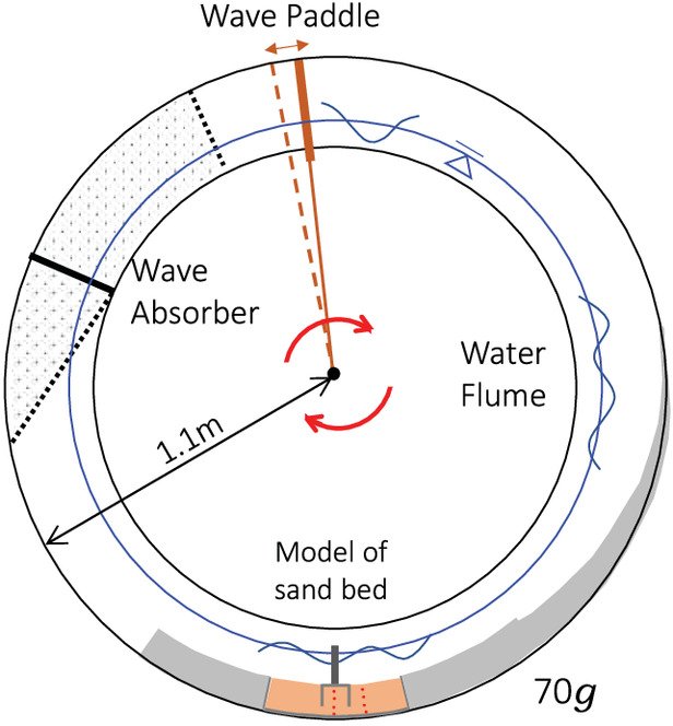
This study used a drum-type centrifuge with a cylindrical water channel with a diameter of 2.2 m (Fig. 2). The water channel rotates under a centrifugal acceleration of , thereby enabling the experiments of wave–soil–structure interactions to be performed under the prescribed centrifugal acceleration. The driving system of a wave-paddle had a feedback system consisting of a servomotor and a laser-type displacement transducer and thus the stroke of the wave paddle could be continuously varied. This allowed modeling of a sequence of storm waves that could start from relatively small waves and then increase to more severe peak waves.
Test Cases
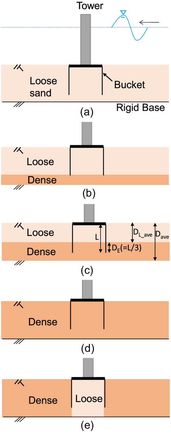
In this study, five cases tests were conducted under (Table 1). As a baseline of these cases, a wave test of level bed without a structure had been performed in past studies (Miyamoto et al. 2021a). The features of each case are illustrated in Fig. 3. The meanings of symbols , , , and in Table 1 are shown in Fig. 3(c). Test Case 1 was a fundamental study of the instability of a suction bucket foundation due to wave-induced liquefaction. The foundation bucket of Case 1 was set in a loose sand bed. This case was for observing the instability of suction bucket foundations in association with liquefaction in loose sand. In Cases 2, 3, 4, and 5, the sand beds had dense sand layers. In Case 2, whereas the foundation bucket was set in a loose sand layer as in Case 1, the bucket tip was supported on the dense sand layer. In Case 3, the bucket tip was embedded in the dense sand layer to a depth of one-third of the bucket-skirt length. In Case 4, the bucket was set entirely in the dense sand bed. The feature of Case 5 is characterized by loose sand inside and underneath the bucket, although the sand bed around the bucket was dense. The situation in this case assumed that the sand inside the bucket was loosened in association with upper seepage flow due to suction during installation, although the bucket was designed to be set in a dense sand layer (see Fig. 1).
| Case | Sand bed model | Aim | |||
|---|---|---|---|---|---|
| 1 | Loose sand bed (D) | 1.37 | 0.00 | 1.37 | Observation of relation between the wave-induced liquefaction and instability of bucket foundation |
| 2 | Loose () and dense () | 0.97 | 0.03 | 1.44 | |
| 3 | Loose () and dense () | 0.72 | 0.34 | 1.43 | Effects of embedment in dense layer |
| 4 | Dense sand bed (D) | 0.00 | 1.00 | 1.50 | |
| 5 | Loose sand for inside the bucket and dense sand for outside the bucket | 1.50 | Effects of loose sand region inside the bucket | ||
Note: = average thickness of entire sand bed; = inner length of skirt of foundation bucket (70 mm); = average thickness of surface layer of loose sand; and = embedded depth of bucket to the dense sand layer obtained from the location of bucket tip and surface of dense layer. As a baseline of these cases, a wave test of level bed without a structure was performed in Miyamoto et al. (2021a).
Experimental Model
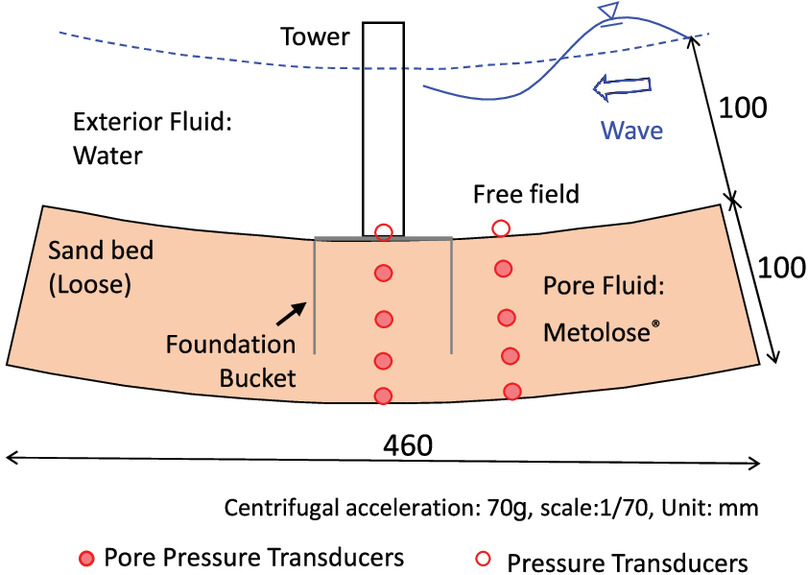
A representative cross-section of the sand deposit model with a suction foundation is shown in Fig. 4. This model corresponds to Case 1, in which the foundation bucket was installed in the loose layer of sand. Water was used as the exterior fluid, and Metolose (Shin-Etsu Chemical, Tokyo, Japan) with a viscosity () of 70 times the viscosity of water and specific weight of 1.02 was used as the pore fluid in order to match the time-scaling laws of soil consolidation and fluid wave propagation (Sassa and Sekiguchi 1999). The sand bed was made with fine sand. The sand material used was silica sand No. 7 (, , , and ). The loosely formed sand beds had relative densities Dr of 43%. The initial soil depth was 100 mm, which corresponded to a 7-m-thick sand bed on the prototype scale, and the fluid depth was kept at 100 mm, equivalent to a 7 m water depth on the prototype scale. It may be instructive here to note that the wave-induced buildup of residual pore pressures and associated liquefaction behavior have been observed in the field up to 50 m water depth (Sassa et al. 2006; Sassa 2016).
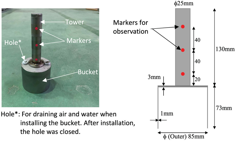
The suction-bucket model is shown in Fig. 5. The bucket had a diameter of 85 mm and a skirt length L of 73 mm. This model scale corresponded to and on the prototype scale, which is about one-half to one-third the scale of a general suction bucket of an offshore wind turbine. The total mass of the tower and lid of the model bucket were adjusted so that the effective overburden stress of the soil inside the bucket under was consistent with that of the prototype scale realized by the weight of an offshore wind turbine and tower. The markers on the tower surface were for visual observation of the tower and bucket movement.
An outline of preparing the soil-structure model is as follows. Sand was poured into a sea of Metolose, where the sand falling height was kept constant, to form a sand bed with a thickness of 100 mm. This procedure realized the sand bed with a relative density Dr of 40%–50%. In Cases 2–5, the dense layer was formed by tamping loose sand deposits with a rod, where every 10-mm sand layer was tamped. The dense sand region formed had a relative density Dr of 80%–90%. After preparing a level bed of sand, the bucket model was manually installed in the sand using a vertical guide. Air or liquid in the bucket outflowed from the hole in the lid (see Fig. 5). Installation of the bucket into the dense layer, in Cases 3–4, required careful tamping of the lid with a plastic hammer. In Case 5, the dense sand region and loose region were formed so as to be separated with a thin aluminum open-cylinder with a thickness of 1.5 mm and an inner diameter of 86 mm, and the cylinder was removed carefully after the completion of the sand bed. This was followed by the installation of the bucket model in the loose region. After the installation of the model bucket in the sand, the hole in lid was closed.
In this study, gradually increasing and decreasing sinusoidal waves were imposed on the soil surface as a severe wave group. The wave period was set equal to 0.1 s, corresponding to 7 s in the field. The maximum wave height of the given wave group corresponds to 3 m in the field, which was calculated from the measured wave pressures at the soil surface using a linear wave theory. The wave severity for a soil bed can be assessed using the cyclic stress ratio (Sassa and Sekiguchi 1999)where = maximum cyclic shear stress induced in the soil under wave loading; = amplitude of the wave-induced fluid pressure fluctuation on the level of the soil surface (); = wave number; and = submerged unit weight of the soil. In this study, loose deposits of sand underwent liquefaction with wave severity .
(1)
The pressure transducers were fixed on the side wall of the water channel on the level of the soil surface. The pore pressure transducers (PPTs) were fixed in the soil with thin wire in two arrays (see Fig. 4). The behavior of the tower of the suction bucket foundation was observed using a high-speed camera at an image rate of .
Instability Process of Suction Bucket Foundation Associated with Wave-Induced Liquefaction
In this chapter, fundamental results from Case 1 on the instability of the suction bucket foundation associated with wave-induced liquefaction are discussed first, followed by the results from Case 2.
Liquefaction Process with and without Suction Bucket Foundation
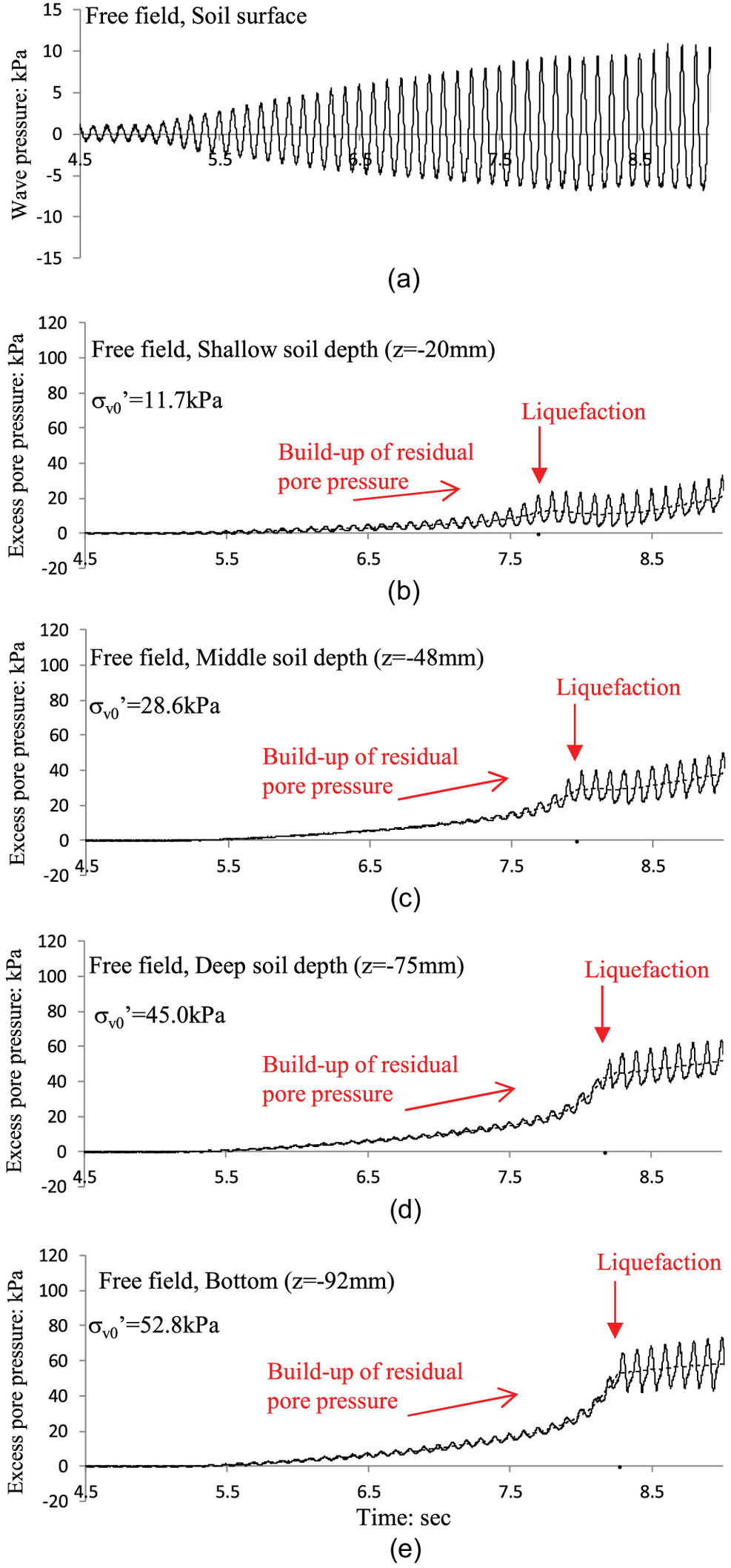
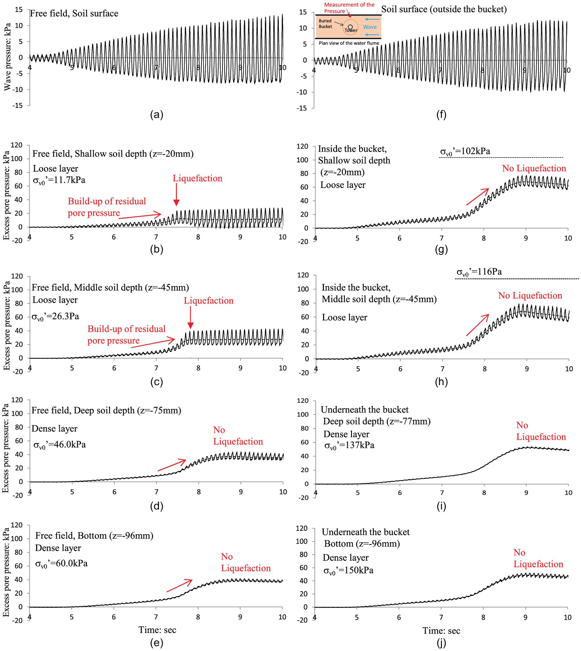
The measured waveforms in the free field are discussed first (Fig. 6). At shallow soil depth, the increase in wave severity resulted in a buildup of residual pore pressure . In fact, the value of reached the level of the initial vertical effective stress there, indicating the occurrence of liquefaction at this soil depth. The criteria for the onset of wave-induced liquefaction such that is described in detail in Miyamoto et al. (2020). In the course of wave loading, liquefaction advanced downward [Figs. 6(c–e)]. Indeed, liquefaction occurred in sequence at shallow soil depth (), at middle soil depth (), at deep soil depth () and at the bottom (). As a consequence of progressive liquefaction, the entire soil bed around the suction bucket foundation underwent liquefaction in the free field. This progressive nature of wave-induced liquefaction has been observed not only under gradually increasing sinusoidal waves as imposed in this study but also under severe irregular waves (Miyamoto et al. 2020).
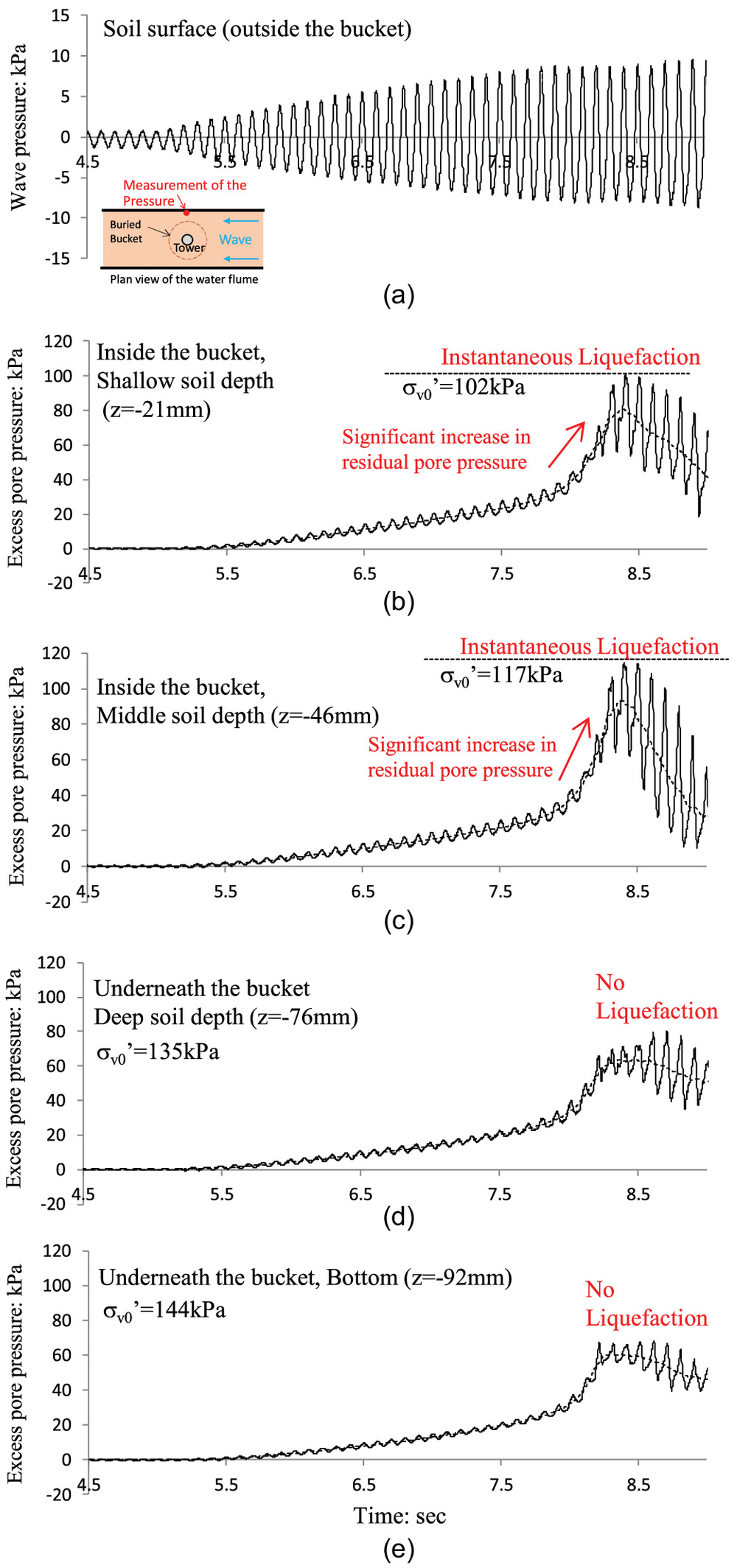
Next, the excess pore pressure responses inside and underneath the suction bucket are discussed (Fig. 7). The wave-induced fluid pressure fluctuation on the level of the soil surface was measured near the bucket [see inset in Fig. 7(a)]. The residual pore pressure built up in the bucket significantly but did not reach the level of initial vertical effective stress , indicating that complete liquefaction did not occur. A closer observation of the pore-pressure response shows that the oscillatory component reached the level instantaneously, followed by the start of dissipation of the residual pore pressure. This indicates that instantaneous liquefaction occurred inside the suction bucket but not complete liquefaction.
The liquefaction process in the level bed without a structure had been observed in past studies (Miyamoto et al. 2021a). The previously mentioned liquefaction process in the free field of the sand bed with the suction bucket, in which the residual pore pressure built up and liquefaction occurred at shallow soil depth and then advanced downward, is the same pattern as the case without a structure.
Relationship between Wave-Induced Liquefaction and Instability of Suction Bucket Foundation
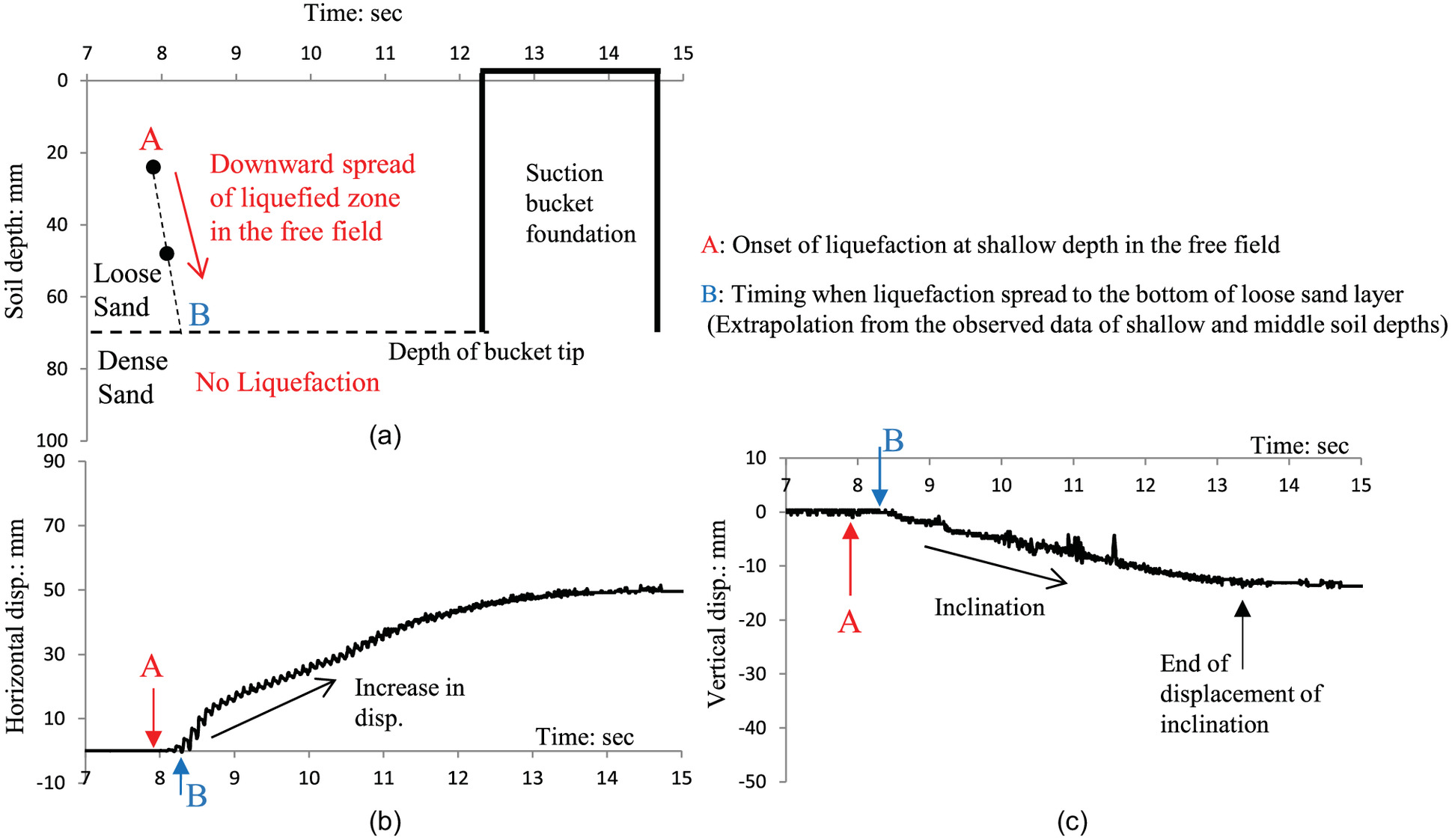
The wave-induced liquefaction in the free field was of a progressive nature, as shown in Fig. 6. The instability and collapse of the foundation bucket were in fact ascribed to the progress of liquefaction in the free field, which stemmed from the dynamic interaction between wave, liquefied soil and subliquefied soil (Sassa et al. 2001). This aspect can be more clearly seen in Fig. 8 where the time histories of the advance of liquefied zone near the foundation bucket [Fig. 8(a)] as well as the displacements of the bucket tower [Figs. 8(b and c)] were shown. The plots in Fig. 8(a) represent the depths of the advancing liquefaction front based on the times of the occurrence of liquefaction shown in Figs. 6(b–e). The displacements of the tower in Figs. 8(b and c) were obtained from the observation of the movements of a marker on the tower located 60 mm above the bucket lid. No significant movement of the tower was observed until the occurrence of liquefaction at shallow soil depth [see point A in Figs. 8(b and c)]. As soon as the liquefaction advanced to the depth of the bucket tip, a significant vibratory motion started and was followed by the development of the residual horizontal displacement [see point B in Fig. 8(b)], as well as the vertical displacement [see point B in Fig. 8(c)]. The vertical displacement stems from the sinking and inclination of the foundation. The residual displacement increased in the course of continued wave loading, and the vibrating motion of the bucket decreased gradually, associated with sinking of the bucket. Finally, the foundation tilted about 90° and sank into the liquefied sand; that is, the foundation collapsed. This means that the progress of liquefaction has a crucial impact on the stability of the suction bucket.
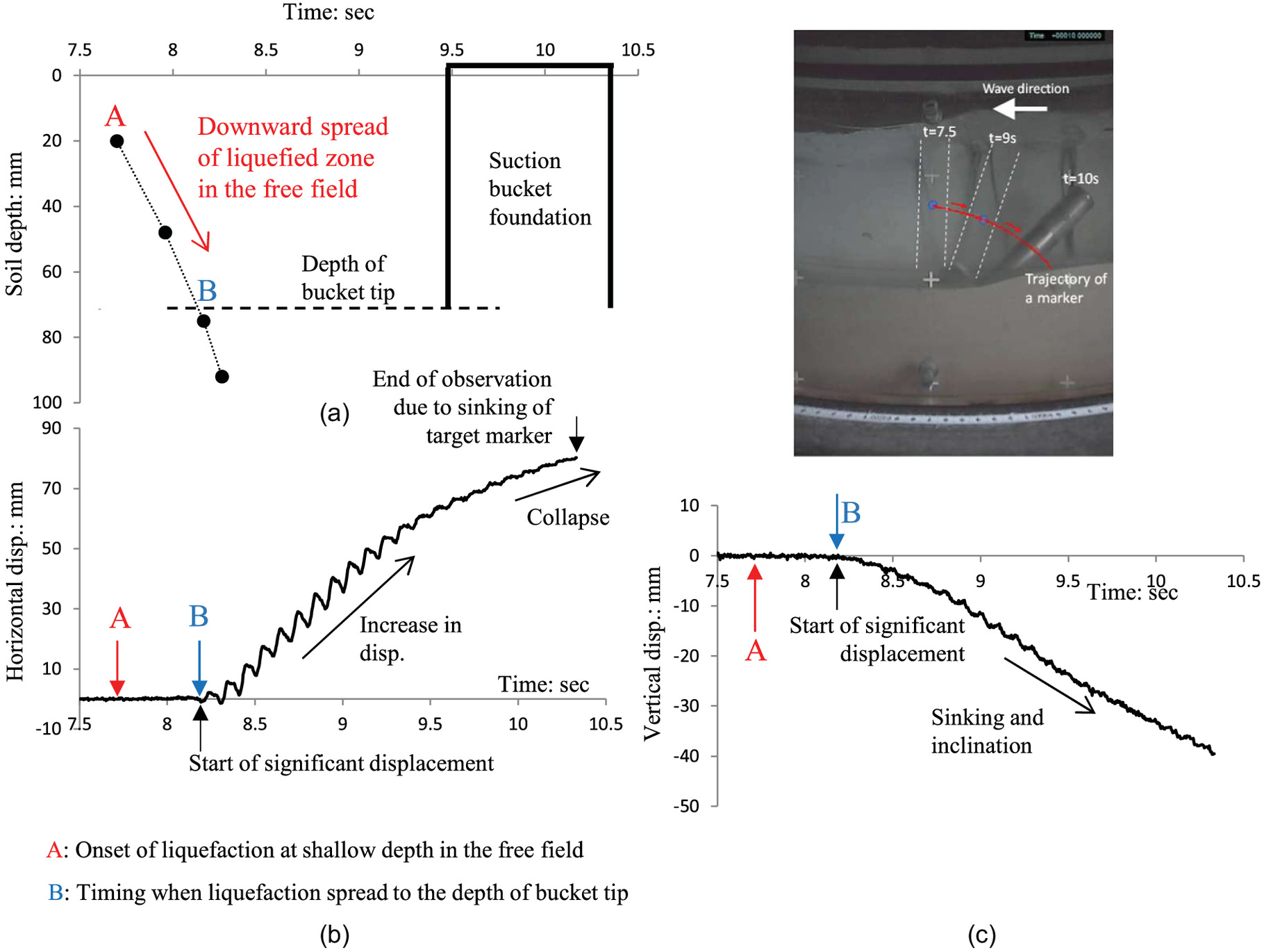
The photograph shown in Fig. 8 indicates that the tilt direction of the tower was opposite to the direction of traveling waves. In the drum centrifuge experiments on monopile (Miyamoto et al. 2021a) where the experimental conditions were almost the same with the conditions of the suction bucket in this study, the monopile tilted to the wave-traveling direction in association with wave-induced liquefaction. It might be worthwhile to investigate the relationships between waves and the tilting directions depending on the types of the structures.
By comparing Figs. 7(b and c) and 8(b), for the period where significant vibratory motion, namely rocking behavior, started to take place around 8.3 s, one can observe that the enhanced oscillatory pore pressures leading to the occurrence of instantaneous liquefaction inside the bucket were closely related to the onset of the significant vibratory or rocking motion of the bucket.
Next, the results from Case 2 will be discussed. In this case, whereas the tip of the suction bucket was supported on the dense layer, the entire bucket was set in the liquefiable layer. The experimental results were essentially the same as in Case 1, except for the pore-pressure responses in the dense sand layer. Following the advance of liquefaction in the free field, instantaneous liquefaction occurred in the bucket, followed by dissipation of the pore pressure. The dense sand layer below the bucket underwent a moderate buildup of residual pore pressure, indicating that liquefaction of the dense sand layer did not occur.
Displacement of the suction bucket associated with the progressive liquefaction was also observed, as shown in Fig. 9, which indicates the same pattern of behavior as in Case 1. Indeed, the foundation exhibited a vibratory motion, and residual displacement started to develop, just after the liquefaction zone advanced to the depth of the bucket tip [see point B in Figs. 8(a–c)]. This indicates that even if the tip of the suction bucket is supported on the dense layer where liquefaction could not occur, the suction bucket foundation could become unstable immediately when the liquefaction advances to the depth of the tip of the bucket in the free field around the bucket. The vertical displacement stems from tilting of the foundation on the dense layer.
Comparing Case 1 and Case 2 indicates that the horizontal and vertical displacements and the speed of development of the displacement were different between these cases. It is a serious concern that the final displacement in Case 2 was about 700 mm at the prototype scale, even though the foundation was supported on the dense layer.
Effects of Embedment of the Suction Bucket in the Dense Layer
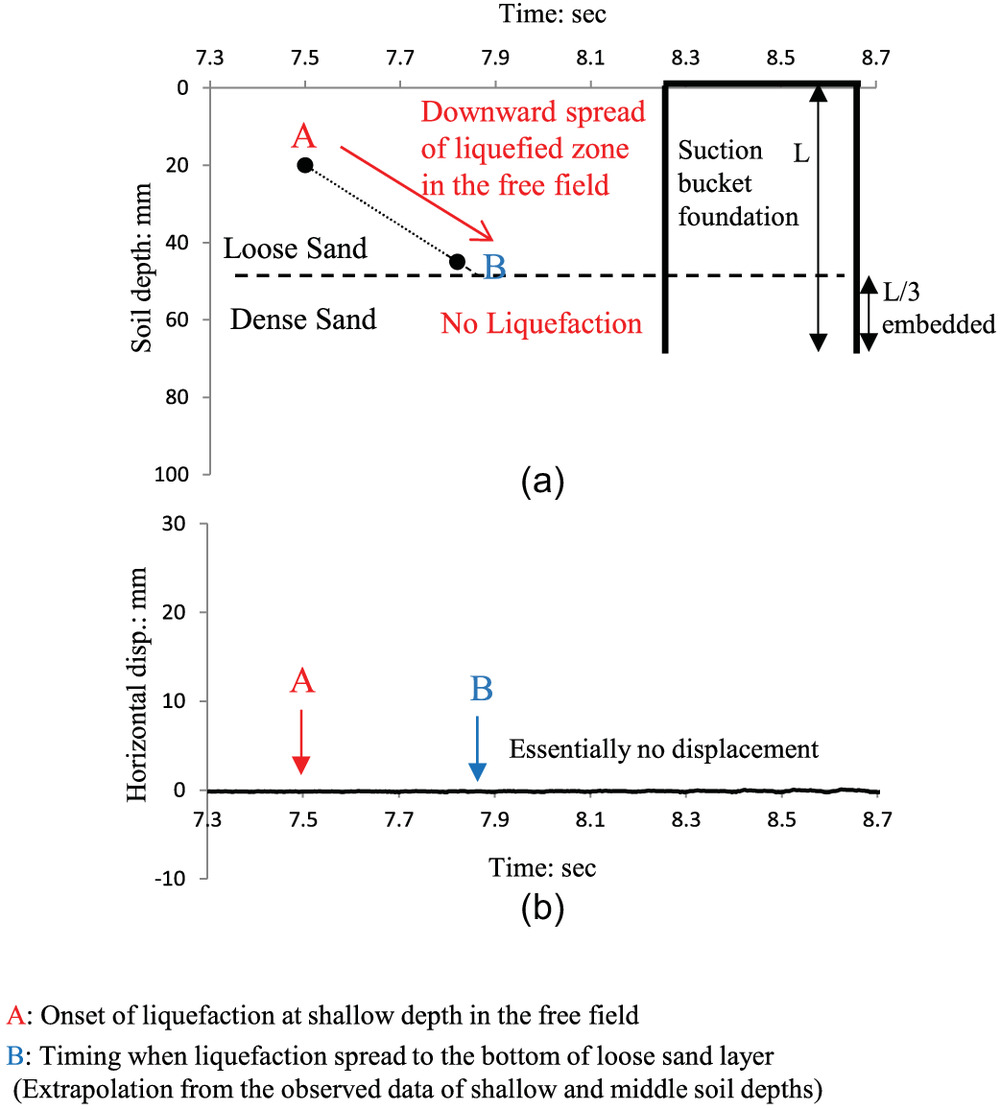
In this chapter, experimental results from Case 3 in which the bucket was embedded to the depth of one-third of the bucket skirt length are discussed. In this case, the foundation remained stable during a severe wave group. Here, liquefaction occurred in the entire loose sand region over the dense sand. The measured waveforms in Case 3 are shown in Fig. 10. Focusing on the soil responses in the free field [Figs. 10(b–e)], progressive liquefaction was observed in the loose sand layer. Indeed, liquefaction took place first at shallow soil depth and then at middle soil depth [Figs. 10(b and c)]. However, in the dense sand layer underneath the loose sand layer, the residual pore pressures built up to a moderate level, indicating that no liquefaction took place [Figs. 10(d and e)]. Next, the soil responses inside and underneath the bucket are focused on [Figs. 10(g–j)]. The sand inside and underneath the bucket underwent an only moderate buildup of residual pore pressures, indicating that neither complete nor instantaneous liquefaction occurred. The oscillatory component of the pore pressure inside the bucket was larger than that underneath it, suggesting the occurrence of undetectable vibration of the bucket due to the wave action.
Embedding the bucket in the dense sand layer to a certain depth prevented the instability of the foundation and its collapse. Indeed, the foundation underwent no significant movement even after the liquefaction occurred in the entire loose sand region, as shown in Fig. 11.
In this case, the bucket-embedded layer corresponding to one-third of the bucket skirt length was nonliquefied. This indicates that the stability in one-third of the soil area above the bucket tip prevented the foundation from collapse. Deeper embedment in the dense stable layer to a depth over would ensure the stability of the bucket foundation. Indeed, in Case 4, where the suction bucket was wholly set in the dense sand layer, liquefaction did not progress, and the bucket remained stable under waves sufficiently severe to cause liquefaction in a liquefiable bed.
Effects of Loosened Sand Bed within the Suction Bucket on Its Stability
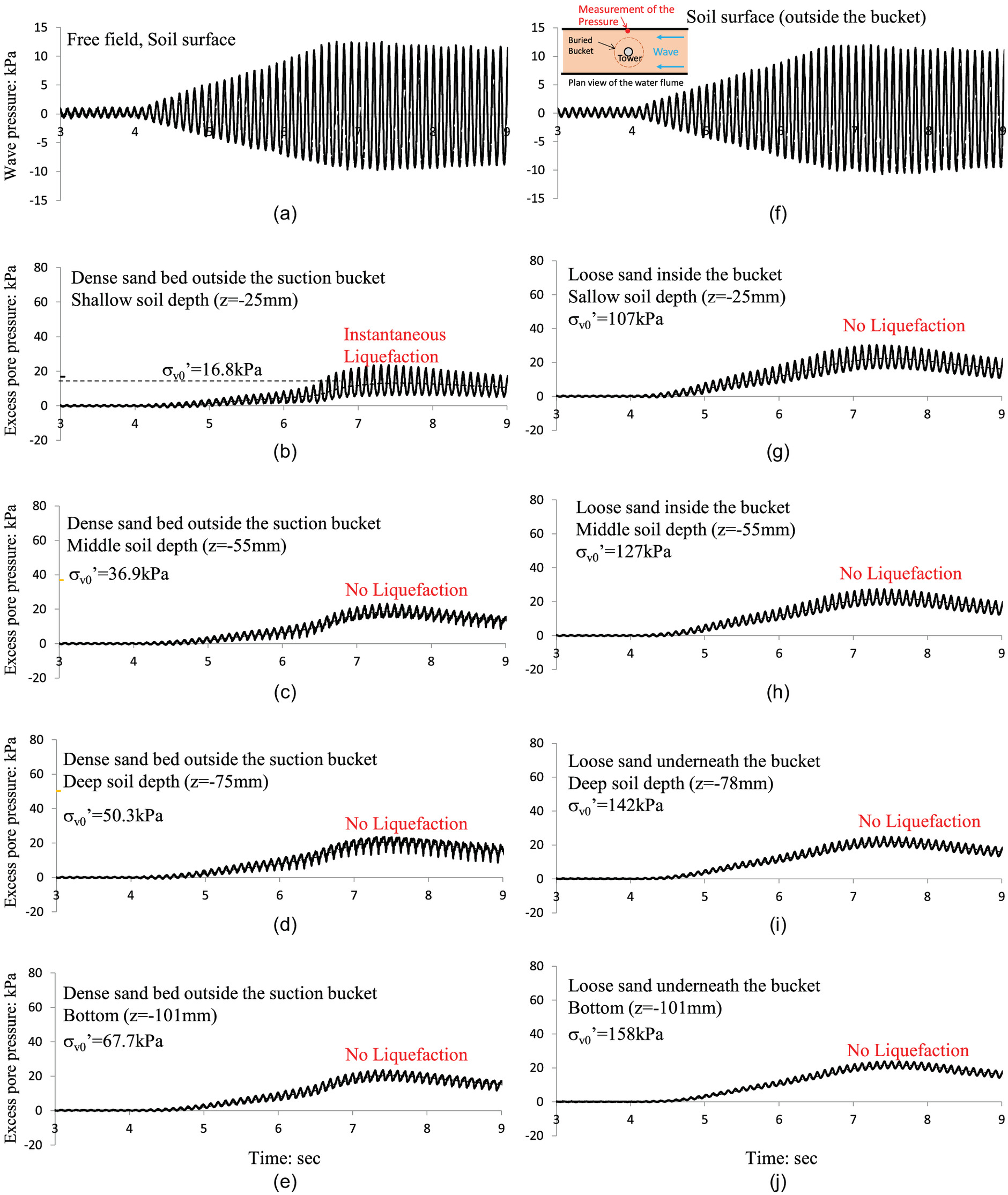
This section addresses practical issues to be clarified and discusses the effects of a loosened sand region induced during the suction bucket installation process. As mentioned in the previous section, the foundation bucket set in a dense layer is stable because liquefaction does not occur nor progress around the bucket foundation. However, in the installation process, the upward seepage flow brings about loosening and heaving of the sand region inside the bucket, which could result in a buildup of residual pore pressure under severe wave loading, leading to liquefaction. This aspect can be addressed in Case 5. This case had a dense sand bed except for the sand region inside and underneath the bucket. Fig. 12 show the pore pressure responses inside and underneath the bucket, as well as around it, in Case 5. It is seen from the responses in the free field around the bucket that the residual pore pressures built up only moderately as a result of the dense sand layer except for the response in the shallow region [Figs. 12(b–e)]. The residual pore pressure at shallow soil depth [Fig. 12(b)] increased to near the level, and the oscillatory component exceeded that level; that is, instantaneous liquefaction occurred. However, the residual pore pressure started to dissipate even under severe wave loading, which did not lead to the advance of liquefaction; in other words, the sand bed around the bucket remained stable. The responses inside and underneath the bucket show that despite the loose sand region, the residual pore pressures there did not rise significantly, remaining in a state far from liquefaction [Figs. 12(g–j)]. This indicates that the stability of the sand around the foundation bucket makes the bucket stable, which makes sand inside the bucket stable even if the sand region inside the bucket has been loosened. These experimental results indicate that the stability, without progress of liquefaction, around the foundation bucket leads to stability of the bucket.
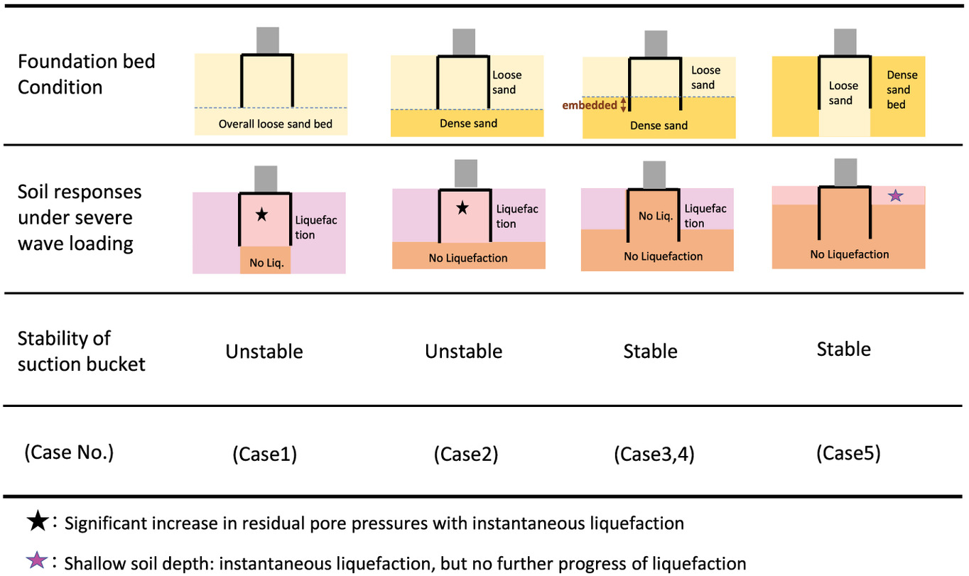
The stability of the suction bucket foundation installed in sand beds under severe wave loading is summarized in Fig. 13. If the suction bucket foundation is installed in a liquefiable bed, that is, a loose deposit of sand, the bucket will be unstable under severe waves as soon as the liquefaction advanced to the depth of the tip of the bucket following the occurrence of liquefaction at shallow soil depth (Case 1 in Fig. 13). Simultaneously, the sand region inside the bucket also becomes unstable in a state of instantaneous liquefaction. Finally, as a result of liquefaction, the bucket foundation will collapse. Even if the tip of the suction bucket is supported on a nonliquefiable layer, the suction foundation could be unstable in the same way as Case 1 (Case 2 in Fig. 13). In contrast, in the case in which the tip of bucket is embedded in the dense layer with a certain thickness (Case 3 in Fig. 13), the suction bucket foundation will remain stable under severe waves, even though the loose sand bed around the bucket undergoes liquefaction. The foundation bucket in the dense sand bed is sufficiently stable (Case 4 in Fig. 13). The sand inside and underneath the bucket will become loose due to the upward seepage flow in the process of bucket installation. The experimental results indicate that the bucket foundation remains stable under sufficiently severe waves that would cause liquefaction in such a liquefiable bed even if the sand layer inside the bucket is loosened as a consequence of bucket installation (Case 5 in Fig. 13). This stems from the fact that instantaneous liquefaction occurred in the free field around the bucket but was not followed by progress of the liquefaction zone. Therefore, it did not lead to liquefaction in the loosened sand inside the bucket. As a consequence, the foundation remained stable. Overall, these results demonstrate that the nonprogress of liquefaction around the foundation bucket is vital to assure the stability of the bucket.
Conclusions
The relationships between wave-induced liquefaction and instability of a suction bucket foundation in sand beds have been discussed, together with the effects of embedment of the bucket in a dense layer on its stability, and effects of loosened sand following the installation of the foundation bucket in an entirely dense sand bed on its stability, through the centrifuge wave tests in a drum channel.
The principal findings obtained from the present study may be summarized as follows:
1.
The process of wave-induced liquefaction was of a progressive nature. Significant vibratory motion, residual displacement and collapse of the bucket foundation were ascribed to the progress of liquefaction. Indeed, as the liquefaction took place at a shallow soil depth and progressed to the depth of the bucket tip, significant displacement of the bucket started and developed markedly in association with the progress of liquefaction, leading to collapse of the foundation.
2.
The effect of embedment of the suction bucket in a dense sand layer on its stability against wave-induced liquefaction was investigated. The bucket-embedded depth in the dense layer to one-third of the bucket skirt length made the bucket stable, despite the spread of liquefaction in the loose sand bed over the dense layer.
3.
The effect of suction bucket installation on the stability of the whole system was investigated. Even when the dense sand inside and underneath the bucket was loosened in association with upper seepage flow during the installation process, the foundation bucket remained stable against severe wave actions.
4.
The stability of the suction bucket foundation in the sand bed under severe wave loading was summarized (Fig. 13). The instability and collapse of the suction bucket were ascribed to the occurrence and progress of liquefaction of the sand bed around the suction bucket.
This study investigated the stability of a monobucket against wave-induced liquefaction. As a wind turbine become larger and larger and the installation depth of a foundation is deeper, the type of suction bucket jacket (SBJ) will be a one-foundation solution (Shonberg et al. 2017). In SBJ, even if seabed instability occurs around only one bucket, the tower can tilt due to its sinking. The whole stability of SBJ-type foundations against wave-induced liquefaction is therefore a subject to be investigated in the future.
Ongoing and future global climate change is expected to change the severity of wave conditions at the world’s coasts (Morim et al. 2019), which would pose a further risk to offshore wind turbine systems as a consequence of wave–seabed–structure interactions, particularly in light of wave-induced liquefaction. The experimental results presented in this paper could contribute to the design of foundations for offshore wind turbines and other related marine structures.
Data Availability Statement
Some data of this study are available from the corresponding author by request.
References
Bienen, B., R. T. Klinkvort, C. D. O’loughlin, F. Zhu, and B. W. Byrne. 2018a. “Suction caissons in dense sand, Part I: Installation, limiting capacity and drainage.” Géotechnique 68 (11): 937–952. https://doi.org/10.1680/jgeot.16.P.281.
Bienen, B., R. T. Klinkvort, C. D. O’loughlin, F. Zhu, and B. W. Byrne. 2018b. “Suction caissons in dense sand, Part II: Vertical cyclic loading into tension.” Géotechnique 68 (11): 953–967. https://doi.org/10.1680/jgeot.16.P.282.
Chen, X., et al. 2018. “Stability analysis of suction bucket foundations under wave cyclic loading and scouring.” Mar. Georesour. Geotechnol. 36 (7): 749–758. https://doi.org/10.1080/1064119X.2017.1387948.
Houlsby, G. T., and B. W. Byrne. 2005. “Design procedures for installation of suction caissons in sand.” Proc. Inst. Civ. Eng. Geotech. Eng. 158 (3): 135–144. https://doi.org/10.1680/geng.2005.158.3.135.
Ito, H., J. Miyamoto, S. Sassa, and H. Sumida. 2021. “Drum centrifuge tests on wave-induced liquefaction and sinking of submerged rubble mound.” [In Japanese.] J. JSCE Ser. B3 (Ocean Eng.) 77 (2): 511–516. https://doi.org/10.2208/jscejoe.77.2_I_511.
Miyamoto, J., S. Sassa, K. Tsurugasaki, and H. Sumida. 2020. “Wave-induced liquefaction and floatation of a pipeline in a drum centrifuge.” J. Waterw. Port Coastal Ocean Eng. 146 (2): 04019039. https://doi.org/10.1061/(ASCE)WW.1943-5460.0000547.
Miyamoto, J., S. Sassa, K. Tsurugasaki, and H. Sumida. 2021a. “Wave-induced liquefaction and instability of offshore monopile in a drum centrifuge.” Soils Found. 61 (1): 35–49. https://doi.org/10.1016/j.sandf.2020.10.005.
Miyamoto, J., S. Sassa, K. Tsurugasaki, and H. Sumida. 2021b. “Wave-induced liquefaction and the stability of suction bucket foundation.” In Proc., 10th Int. Conf. on Scour and Erosion (ICSE10), 904–913. London: International Society for Soil Mechanics and Geotechnical Engineering.
Morim, J., et al. 2019. “Robustness and uncertainties in global multivariate wind-wave climate projections.” Nat. Clim. Change 9 (9): 711–718. https://doi.org/10.1038/s41558-019-0542-5.
OWA (Offshore Wind Accelerator). 2019. Suction installed caisson foundations for offshore wind: Design guidelines, 1–92. London: Carbon Trust.
Ragni, R., B. Bienen, S. Stanier, C. O’Loighlin, and M. Cassidy. 2020. “Observation during suction bucket installation in sand.” Int. J. Phys. Modell. Geotech. 20 (3): 132–149. https://doi.org/10.1680/jphmg.18.00071.
Sassa, S. 2016. “Wave-induced liquefaction and sediment flow dynamics: The latest case study.” [In Japanese.] J. JSCE Ser. B3 (Ocean Eng.) 72 (2): 378–383. https://doi.org/10.2208/jscejoe.72.I_378.
Sassa, S., and H. Sekiguchi. 1999. “Wave-induced liquefaction of beds of sand in a centrifuge.” Géotechnique 49 (5): 621–638. https://doi.org/10.1680/geot.1999.49.5.621.
Sassa, S., and H. Sekiguchi. 2001. “Analysis of wave-induced liquefaction of sand beds.” Géotechnique 51 (2): 115–126. https://doi.org/10.1680/geot.2001.51.2.115.
Sassa, S., H. Sekiguchi, and J. Miyamoto. 2001. “Analysis of progressive liquefaction as a moving-boundary problem.” Géotechnique 51 (10): 847–857. https://doi.org/10.1680/geot.2001.51.10.847.
Sassa, S., H. Takahashi, Y. Morikawa, and D. Takano. 2016. “Effect of overflow and seepage coupling on tsunami-induced instability of caisson breakwaters.” Coastal Eng. 117 (Nov): 157–165. https://doi.org/10.1016/j.coastaleng.2016.08.004.
Sassa, S., T. Takayama, M. Mizutani, and D. Tsujio. 2006. “Field observations of the build-up and dissipation of residual pore pressures in seabed sands under the passage of storm waves.” J. Coast. Res. 39 (Special Issue): 410–414.
Shonberg, A., M. Harte, A. Aghakouchak, C. S. D. Brown, M. P. Andrade, and M. A. Liingaard. 2017. “Suction bucket jackets for offshore wind turbines: Applications from in situ observations.” In Proc., of TC209 Workshop, 19th ICSMGE-Seoul, Foundation Design of Offshore Wind Structures, 65–77. London: International Society for Soil Mechanics and Geotechnical Engineering.
Stroescu, I.-E., and P. Frigaard. 2016. “Scour properties of mono bucket foundation.” In Proc., 8th Int. Conf. on Scour and Erosion, 335–341. London: CRC Press.
Sumer, B. M. 2014. “Liquefaction around marine structures.” In Vol. 39 of Advanced series on ocean engineering. Singapore: World Scientific.
Sumer, B. M., and J. Fredsøe. 2002. “The mechanics of scour in the marine environment.” In Vol. 17 of Advanced series on ocean engineering. Singapore: World Scientific.
Sumer, B. M., F. Hatipoglu, J. Fredsoe, and S. K. Sumer. 2006. “The sequence of soil behaviour during wave-induced liquefaction.” Sedimentology 53 (3): 611–629. https://doi.org/10.1111/j.1365-3091.2006.00763.x.
Tran, M. N., M. F. Randolph, and D. W. Airey. 2005. “Study of seepage flow and sand plug loosening in installation of suction caissons in sand.” In Proc., 5th Int. Offshore and Polar Engineering Conf., 516–521. Mountain View, CA: International Society of Offshore and Polar Engineers.
Zhu, F., B. Bienen, C. O’loughlin, M. J. Cassidy, and N. Morgan. 2019. “Suction caisson foundations for offshore wind energy: Cyclic response in sand and sand over clay.” Géotechnique 69 (10): 924–931. https://doi.org/10.1680/jgeot.17.P.273.
Zhu, F. Y., C. D. O’loughlin, B. Bienen, M. J. Cassidy, and N. Morgan. 2018. “The response of suction caissons to long-term lateral cyclic loading in single-layer and layered seabeds.” Géotechnique 68 (8): 729–741. https://doi.org/10.1680/jgeot.17.P.129.
Information & Authors
Information
Published In

Journal of Geotechnical and Geoenvironmental Engineering
Volume 149 • Issue 4 • April 2023
Copyright
This work is made available under the terms of the Creative Commons Attribution 4.0 International license, https://creativecommons.org/licenses/by/4.0/.
History
Received: Aug 8, 2022
Accepted: Dec 7, 2022
Published online: Feb 7, 2023
Published in print: Apr 1, 2023
Discussion open until: Jul 7, 2023
Authors
Metrics & Citations
Metrics
Citations
Download citation
If you have the appropriate software installed, you can download article citation data to the citation manager of your choice. Simply select your manager software from the list below and click Download.