Sands Subjected to Repetitive Loading Cycles and Associated Granular Degradation
Publication: Journal of Geotechnical and Geoenvironmental Engineering
Volume 149, Issue 11
Abstract
This study examines the load-deformation response of sands subjected to high- and low-stress cycles, i.e., both ends of the Wöhler’s fatigue curve. At high peak cyclic stress , the terminal void ratio decreases with due to crushing-dependent densification, and it can be smaller than when the peak stress approaches the yield stress . When , the soil retains memory of the initial fabric even after a very large number of cycles, and the terminal void ratio correlates with the initial void ratio . Data show that the maximum change in relative density leads to simple strategies to estimate the maximum settlement for first-order engineering analyses. In agreement with Wöhler’s fatigue, tipping points in void ratio and stiffness trends occur at a small number of high-stress cycles or after a large number of small-stress cycles. During repetitive loading, sands stiffen with the number of cycles to reflect increased interparticle coordination following crushing, as well as contact flattening due to asperity breakage and fretting. The strong correlation between the resilient modulus and the maximum shear modulus suggests the possible application of geophysical methods based on shear wave propagation to monitor geosystems subjected to repetitive loading cycles.
Introduction
Particles may crush when soils experience high effective stress such as beneath pile tips, steel rollers, and reservoirs during oil extraction. Particle crushing affects dilative tendencies, compressibility, and shear strength (Lade and Yamamuro 1996; Feda 2002; Uygar and Doven 2006; Sadrekarimi and Olson 2010). Furthermore, produced fines increase the soil specific surface area and reduce the hydraulic conductivity; they may migrate and clog the formation (Valdes and Santamarina 2006, 2008; Hafez et al. 2021) and could eventually cause undrained shear failures (e.g., railway ballast; Indraratna et al. 1997).
Repetitive loading cycles add the possibility of granular fatigue. Then, the load-deformation response may not be a single monotonic trend of the number of cycles and exhibit “tipping points” as observed in some datasets (Suiker et al. 2005; Indraratna et al. 2003, 2006; Werkmeister 2003; Wichtmann 2005; Werkmeister et al. 2005; da Fonseca et al. 2013; Indraratna and Nimbalkar 2013). In agreement with Wöhler’s S-N fatigue curve, particle degradation would be expected earlier under high-stress cycles than in low-stress cycles.
Granular degradation under cyclic loading affects the long-term performance of engineered geosystems. The purpose of this study is to advance our understanding of the load-deformation response and associated granular degradation when sands are subjected to repetitive vertical loading cycles under zero-lateral strain conditions. We explore both ends of Wöhler’s curve, i.e., high- and low-stress cycles, and monitor stiffness evolution and granular degradation.
Experimental Study
The experimental program consists of two end-member conditions: (1) high-stress cycles (peak stress , 5, 10, 15, and 25 MPa); and (2) low-stress cycles ().
Tested sand. The KAUST 20/30 sand used in all tests is a uniform quartzitic sand readily found in western Saudi Arabia. Table 1 summarizes its index properties including the coefficient of uniformity , particle shape (i.e., roundness), extreme void ratios and , and yield stress under monotonic loading, i.e., the initiation of generalized crushing. (Note: there is no reliable criterion for selecting the yield stress; we fit the data using a hyperbolic function with asymptotically correct void ratios at low and high stresses, and adopt the point of maximum curvature as an indicator of yield stress.) For comparison and in order to confirm “tipping points,” we run a parallel set of low amplitude tests using Ottawa 20/30 another quartzitic sand, well studied in the literature; its index properties are included in Table 1 as well.
| Property | Core study: KAUST 20/30 sand | Complementary study: Ottawa 20/30 sand |
|---|---|---|
| Particle size, (mm) | 0.60–0.85 | 0.60–0.85 |
| Mineralogy | Quartz 100% | Quartz 100% |
| Roundness, | 0.60 | 0.90 |
| Coefficient of uniformity, | 1.20 | 1.20 |
| Specific gravity, | 2.65 | 2.65 |
| Maximum void ratio, | 0.786 | 0.742 |
| Minimum void ratio, | 0.533 | 0.502 |
| Critical state friction angle, | 31° | 27° |
| Intercept (in ) | 0.845 | 0.802 |
| Slope (in ) | 0.074 | 0.047 |
| Yield stress, (monotonic loading) | 10 MPa (at ) | 28 to 48 MPa (-to-95%) |
Instrumented oedometer cells. High- and low-stress tests use a floating ring oedometer cell configuration to minimize the effect of wall friction (Fig. 1). The tall rings guide the loading caps to prevent wall jamming and allow for thick specimens in order to avoid near-field effects in wave propagation. The wall thickness in both cases is designed to ensure a radial strain in order to maintain conditions during repetitive loading (Okochi and Tatsuoka 1984). The resulting oedometer cell dimensions are summarized in Fig. 1.
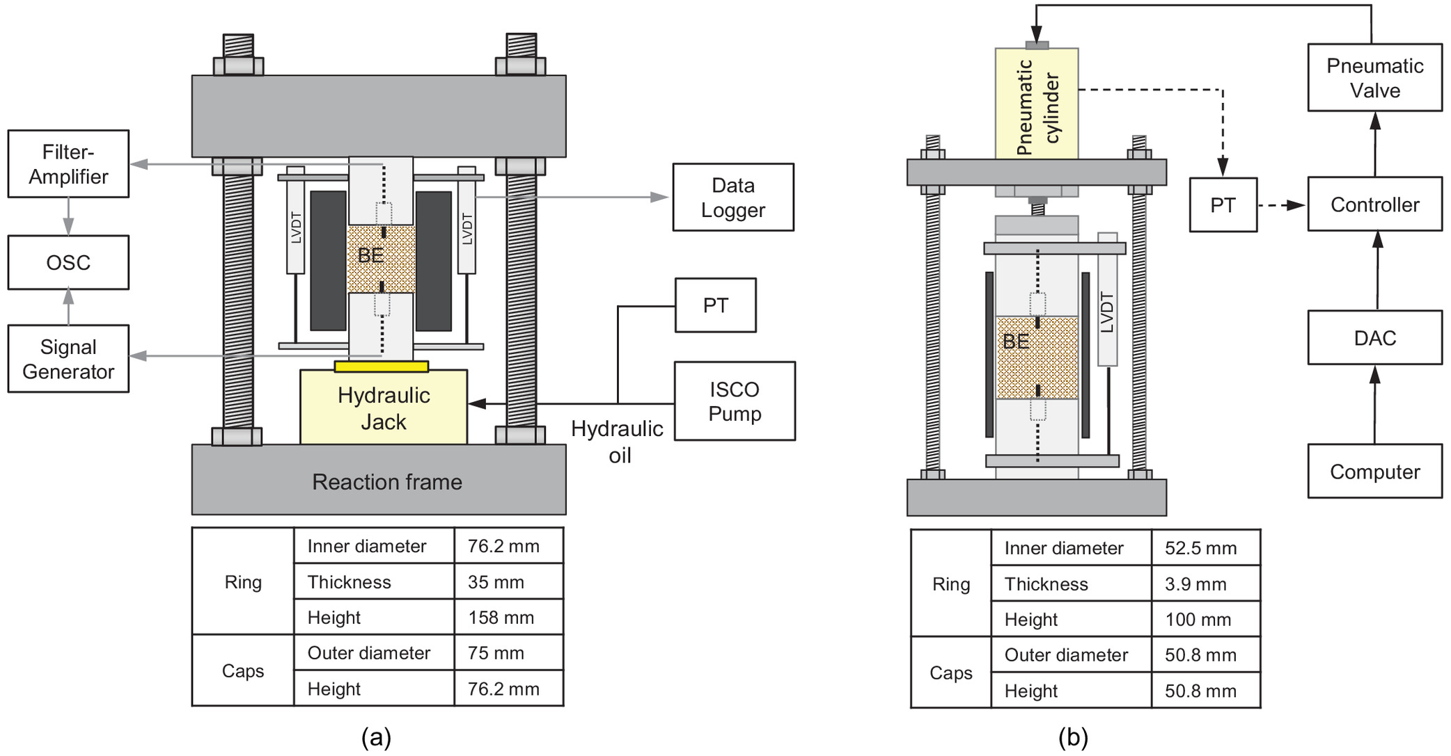
The repetitive loading system for high-stress cycles consists of a hydraulic jack (Enerpac, RSM-1000) connected to a hydraulic pump (ISCO–1000D) to produce a rectangular load cycle. The repetitive loading system for 1 million cycles involves a proportional-integral-derivative (PID) controller to generate the sinusoidal pressure cycle that drives the pneumatic cylinder (Fig. 1; details in Park and Santamarina 2019). LVDTs clamped to the top and bottom caps track changes in specimen height (TransTek DC 0242–Data logger Keysight 34970A).
Shear wave measurements for both high- and low-stress tests involve bender elements mounted on the top and bottom caps (Lee and Santamarina 2005). Both bender elements are parallel type to minimize crosstalk and for improved shielding, and cantilever 5 mm into the soil mass to ensure mechanical coupling. A function generator sends a 10 volt step signal every 50 ms to the source bender element (Keysight 33210A), and a filter amplifier connected to the receiver bender element conditions the received signal (500 Hz high-pass and 200 kHz low-pass window; Krohn-Hite 3364). We stack 1,024 signals to enhance the signal-to-noise ratio and store the resulting signal in the digital storage oscilloscope [Keysight DSOX 2014A; stacking design in Santamarina and Fratta (2005)].
Specimen preparation and test protocols. The specimen preparation method involves a predetermined tamping energy per layer to attain the target relative density in each case (see details for dry tamping-based specimen preparation methods in Zhu et al. (2020, 2021). Specimens have a relative density for high-stress cycles, and three different relative densities , 50%, and 70% for low-stress cycles.
The loading sequence consists of monotonic loading to reach the initial vertical stress followed by the repetitive loading cycles:
•
High-stress (): We start the repetitive cycles from five different initial effective stress levels , 1, 2, 3, and 5 MPa, and impose five different cyclic amplitudes , 4, 8, 12, and 20 MPa so that the ratio between the peak cyclic stress and the initial stress is the same in all cases, i.e., (Table 2). The loading period is for all specimens. Finally, we unload the specimens without applying additional static stress to avoid any additional grain crushing at these high-stress levels.
•
Low-stress (): The initial vertical stress is and the repetitive cycles go from to ; thus and the stress amplitude ratio is in all tests. The selected loading cycle period is a compromise between the sand relaxation time and the total test duration (139 days). After the stress cycles, we increase the static load to . Finally, we unload specimens.
| Test conditions | No. | (MPa) | (MPa) | (MPa) | “As-prepared” void ratio | Void ratio at | Model parameters | ||||
|---|---|---|---|---|---|---|---|---|---|---|---|
| KAUST 20/30 sand | |||||||||||
| High stress cycles | [1] | 0.5 | 2 | 2.5 | 5 | 0.597 | 0.587 | 0.572 | 0.548 | 0.51 | 8 |
| [2] | 1 | 4 | 5 | 5 | 0.589 | 0.577 | 0.559 | 0.533 | 0.54 | 8 | |
| [3] | 2 | 8 | 10 | 5 | 0.589 | 0.572 | 0.548 | 0.525 | 0.53 | 7 | |
| [4] | 3 | 12 | 15 | 5 | 0.590 | 0.568 | 0.533 | 0.487 | 0.50 | 9 | |
| [5] | 5 | 20 | 25 | 5 | 0.591 | 0.561 | 0.486 | 0.385 | 0.46 | 9 | |
| Low-stress cycles | [6] | 0.067 | 0.1 | 0.167 | 2.5 | 0.735 | 0.731 | 0.727 | 0.702 | 0.32 | |
| [7] | 0.067 | 0.1 | 0.167 | 2.5 | 0.694 | 0.693 | 0.692 | 0.671 | 0.32 | ||
| [8] | 0.067 | 0.1 | 0.167 | 2.5 | 0.639 | 0.637 | 0.636 | 0.621 | 0.38 | ||
| Ottawa sand | |||||||||||
| One millime cycles | [9] | 0.067 | 0.1 | 0.167 | 2.5 | 0.673 | 0.669 | 0.665 | 0.643 | 0.35 | |
| [10] | 0.067 | 0.1 | 0.167 | 2.5 | 0.631 | 0.627 | 0.624 | 0.606 | 0.30 | ||
| [11] | 0.067 | 0.1 | 0.167 | 2.5 | 0.583 | 0.582 | 0.580 | 0.569 | 0.39 | ||
This study refers to low-stress tests when stress conditions are significantly below the yield stress —in other words, when there will be no obvious contact damage during monotonic loading. Furthermore, we aim to extend monotonic loading beyond the stress at repetitive loading (i.e., ) to explore stiffness evolution past mechanical aging (without the effects of crushing). For example, the static-repetitive-static loading sequence allows us to examine the effect of repetitive loading on changes in value and exponent [see example in Park and Santamarina (2019)].
Shear wave signatures are gathered at the top of loading at preselected cycles in both high- and low-stress studies. At the end of each test, we measure particle size distribution using sieve analysis and observe grains using optical and scanning electron microscopy. Given the relatively small fines fraction, we place special emphasis on fines separation (prolonged sieve shaking protocols without overloading the sieves), careful fines recovery, and precision weighing (= 0.0001g–ADB 200-4; KERN). Optical microscopy images confirm clean retained grains.
Experimental Results: Analyses
Particle Degradation
Fig. 2 presents particle size distributions before loading, and after high-stress and low-stress cycles. The amount of fines produced increases with the maximum stress level . The repetitive load test that reaches produces significantly more fines than the monotonic load that reaches . The low-stress cycles produce some fines as well even though the maximum stress is much lower than the yield stress (Fig. 2). The original particle size distribution before testing consists of 100% passing sieve #20 and retained on sieve #30; post-testing, the fines fraction passing sieve #30 is after monotonic loading to 24 MPa, 0.6% to 30% after high-stress repetitive loading cycles (increases with stress amplitude ), and less than 0.8% for the low-stress repetitive loading cycles regardless of the initial packing density.

Based on our prior experience and published studies, we can anticipate higher fine production when more angular particles and higher initial void ratio specimens are involved (Lee and Farhoomand 1967; Sadrekarimi and Olson 2010). The particle size and coordination number affect crushing. Smaller size particles tend to exhibit higher tensile strength when subjected to an axial force. On the other hand, smaller particles typically have a lower coordination number in a granular packing; therefore they are more prone to splitting (McDowell 1999; Coop et al. 2004; Guimaraes et al. 2007; Sadrekarimi and Olson 2010).
Optical and scanning electron microscopy (SEM) provide further insight into the evolution of particle degradation. Fig. 3 shows optical microscopy images of sand particles after repetitive loading to (). The smaller particles produced during crushing have more angular shapes [see similar results in Guimaraes et al. (2007) and Sadrekarimi and Olson (2010)].

SEM images in Fig. 4 capture additional details, such as surface abrasion and fretting, asperity breakage, clean planar surface produced by tensile splitting, sharp blade-like fine particles, V-shaped pits, surface scratches, conchoidal fractures, preferential splitting of finer particles along cleavage planes, and sawtooth surfaces that result from interacting conchoidal fractures. (See Helland et al. 1997; Martinelli et al. 2020. Note: fretting refers to contact damage when the interacting bodies experience small repetitive movements tangential to the surface.) Clearly, surface abrasion, asperity breakage, and fretting prevail when sand grains experience a large number of low-stress cycles [Figs. 4(a and b)]. By contrast, sand particles subjected to high-stress cycles tend to split along cleavage planes to produce platy particles; the finer particles are flatter and more angular [Figs. 4(i–l)].

Void Ratio Evolution
Fig. 5 presents the change in void ratio versus the vertical effective stress for the five KAUST 20/30 sand specimens subjected to high-stress amplitude cycles. We superimpose a complementary monotonic oedometer test data gathered at the same initial relative density and loaded to a maximum vertical stress . The yield stress corresponds to the point of maximum curvature. Repetitive loading cycles—all with the same ratio—cause more significant volume contraction as the peak cyclic stress increases from (Test 1) to 25 MPa (Test 5). The void ratio for specimens that experience and reaches values smaller than the minimum void ratio . On the other hand, the gray square in Fig. 5 illustrates the change in void ratio for a specimen subjected to low-stress cycles (Test 8 in Table 2). Fig. 6 presents the void ratio evolution with the number of cycles in both and scales to highlight trends. Marked changes in the void ratio occur in the first 10 cycles, and the volume contraction becomes more pronounced as the maximum stress increases from 2.5 to 25 MPa.
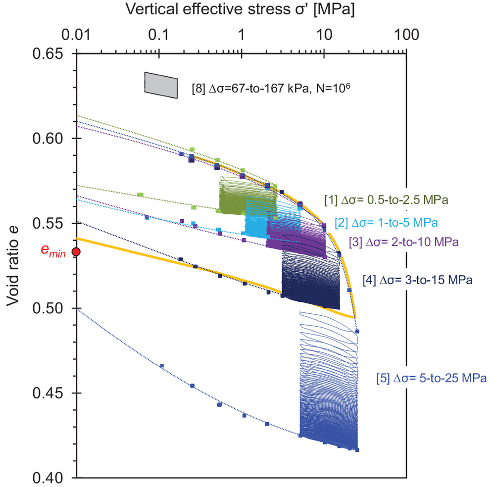
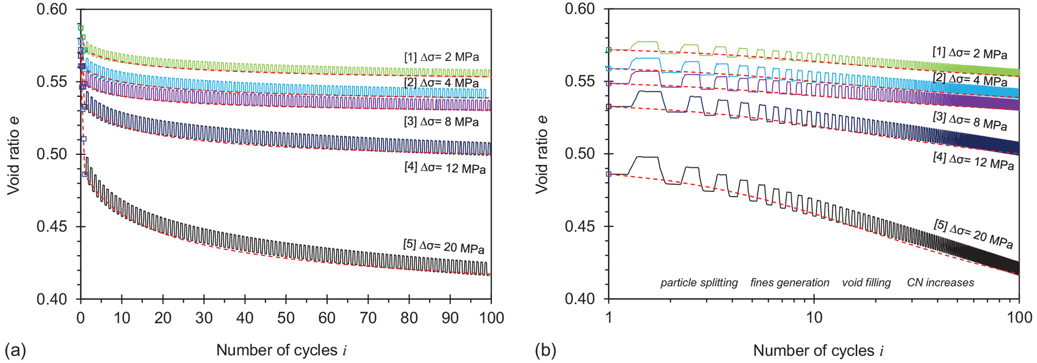
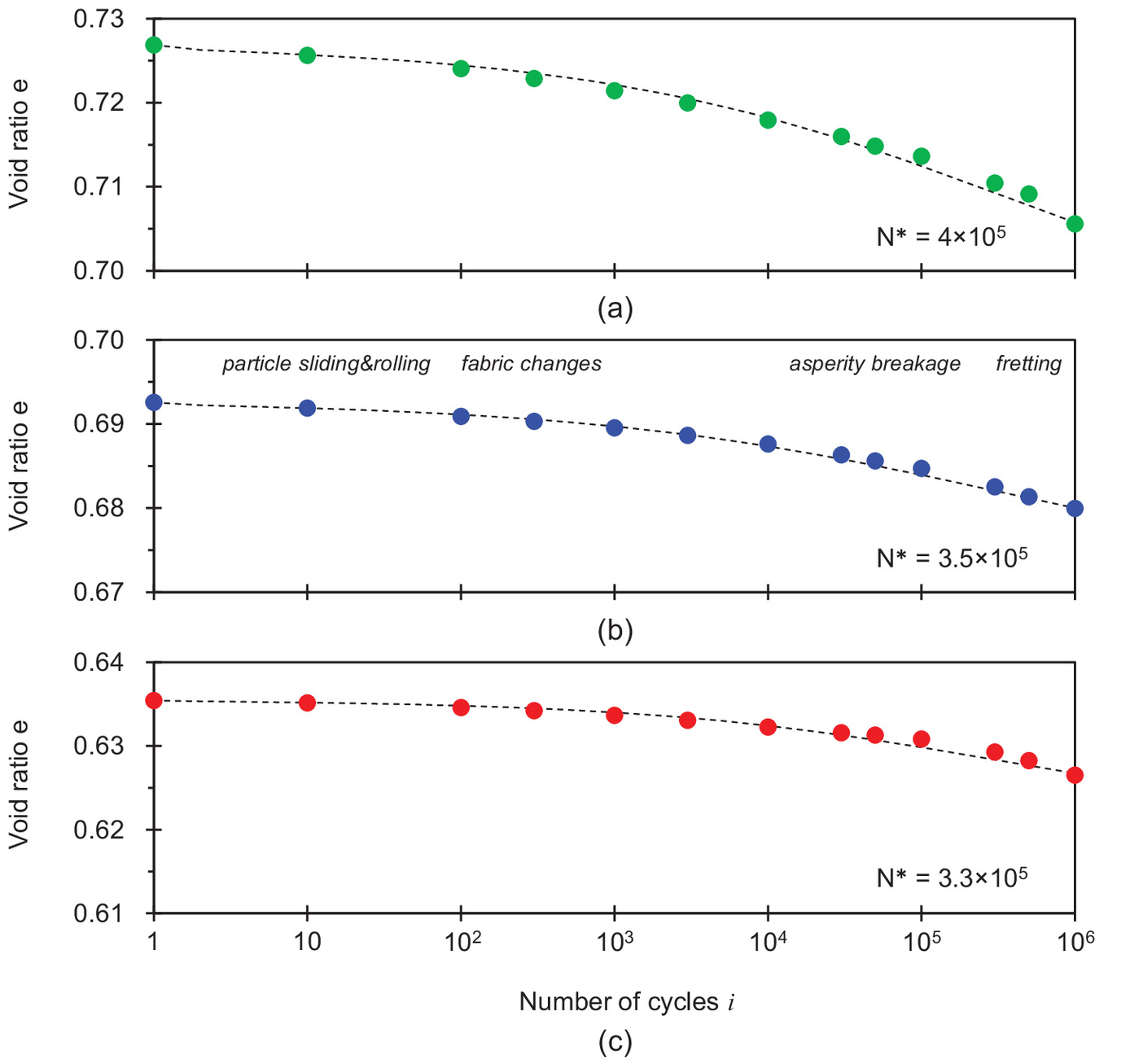
Fig. 7 shows the change in the void ratio versus the number of cycles for the three KAUST 20/30 sand specimens subjected to low-stress cycles. The complementary analogous study conducted with Ottawa 20/30 sands exhibits very similar trends (Fig. S1 ).
The complete dataset for high- and low-stress cycles is plotted in terms of the cumulative volumetric strain in Figs. 8(a and b); for completeness, volumetric strain data extracted from published studies are superimposed on Fig. 8(b). Both high- and low-stress data deviate from the initial linear trends (in scale) once the number of cycles exceeds a “tipping point.” A change in trends hints to the emergence of a new deformation mechanism apparently associated with contact fatigue.
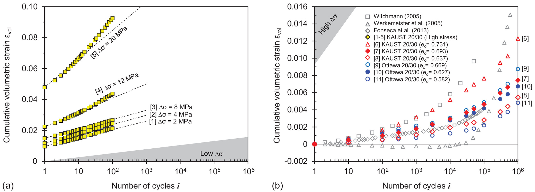
Terminal void ratio. A soil will evolve towards a stable asymptotic terminal void ratio as when subjected to repetitive loading (D’Appolonia and D’Appolonia 1967; Narsilio and Santamarina 2008). The terminal void ratio can be inferred by fitting void ratio trends using asymptotically correct functions. Previous studies show that a modified hyperbolic function properly matches volumetric changes under -repetitive loading [modified from Chong and Santamarina (2016)]:where the void ratio after the th cycle is a function of the void ratio after the first cycle and the terminal void ratio as . The exponent is . Half of the asymptotic contraction takes place when , i.e., immediately after the characteristic cycle number . Eq. (1) fits both high- and low-stress data well. Model parameters listed in Table 2 show that both the terminal void ratio and the characteristic cycle number decrease as the peak stress increases.
(1)
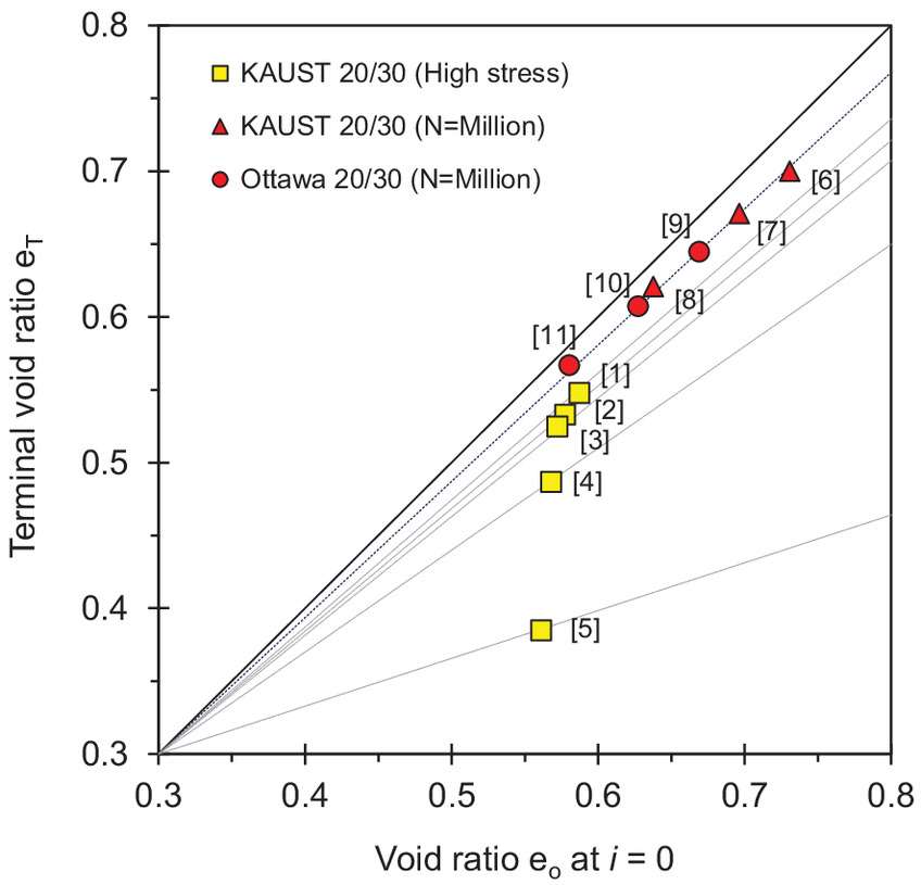
Fig. 9 presents the terminal void ratio against the initial void ratio at for all specimens tested in this study. The terminal void ratio for low-stress cycles varies with the initial void ratio (red circles and triangles, ). The proportionality between and for low-stress cycles suggests that sand specimens retain memory of their initial fabric even after a very large number of cycles. On the other hand, the terminal void ratio for high-stress cycles depends on the peak stress due to crushing-dependent densification.
Time-stepping numerical simulations are expensive and subject to error accumulation. Instead, robust empirical functions that satisfy asymptotic conditions—such as Eq. (1)—can be combined with constitutive models to ensure equilibrium and compatibility in efficient hybrid numerical simulators (Suiker and de Borst 2003; Niemunis et al. 2005; François et al. 2010; Pasten et al. 2014; Masin 2021).
Maximum change in relative density . The ratio between the asymptotic contraction and the extreme void ratio range for a given sand can help us estimate the maximum change in relative density at with respect to the initial relative density at during repetitive loading:
(2)
(3)
Data normalization with respect to index properties allows us to superimpose data for different sands and test conditions. Fig. 10 presents versus data: (1) all specimens tested in this study under low- and high-stress cycles; and (2) data gathered under low-stress cycles in this and previous studies. As the terminal densities for high-stress cycles and 25 MPa result in , the predicted asymptotic relative density will exceed . The maximum possible change in relative density corresponds to a very loose specimen subjected to and reaching , so the maximum possible change in relative density is [cutoff in Fig. 10(a)].
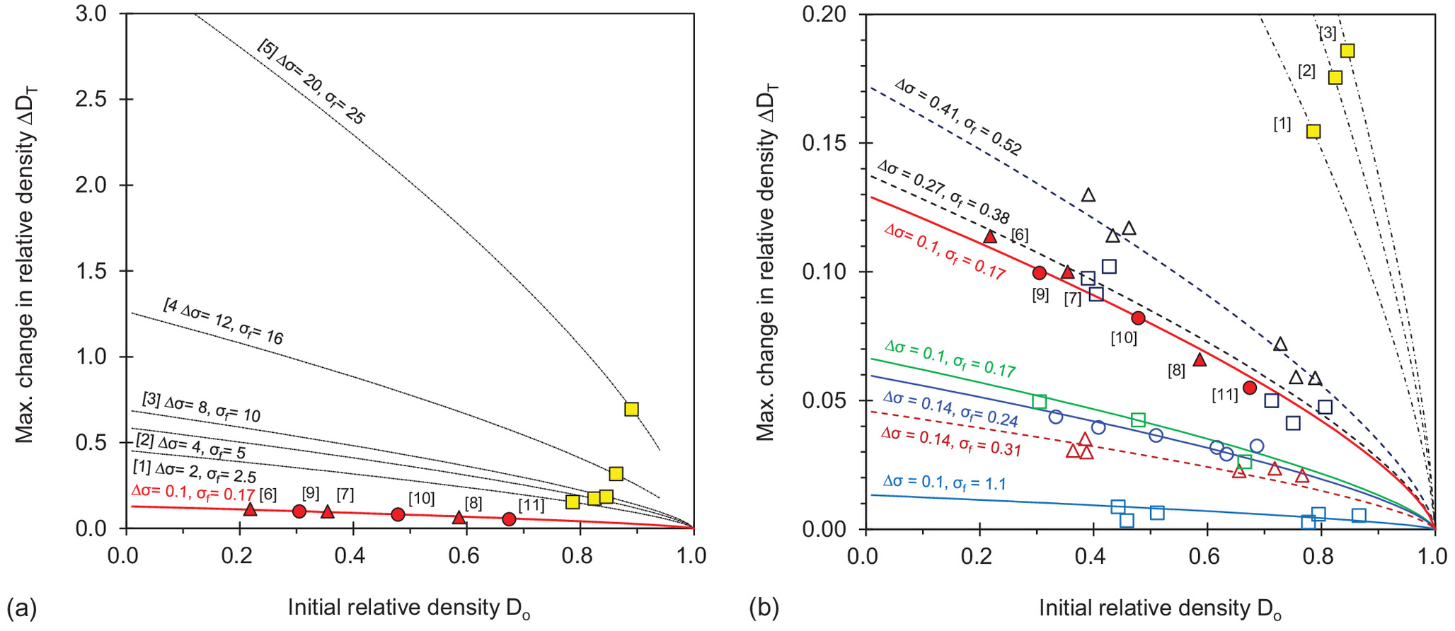
The following curve-fitting function satisfies the data and allows us to predict the maximum change in relative density as a function of the stress amplitude and the initial relative density :
(4)
The exponent determines the function curvature; we adopt in all cases to limit the number of degrees of freedom during curve fitting. The fitted parameter increases with peak cyclic stress from for to for . Fig. S2 shows a trend between fitted values and the maximum stress . The data spread is in part due to the emergence of tipping points and underlying differences in grain degradation with .
The settlement caused by repetitive loads is the depth integral of vertical strain . Then, the anticipated maximum change in relative density can be used to obtain first-order estimates of the maximum settlement a geosystem may experience during repetitive loading.
Shear Wave Velocity
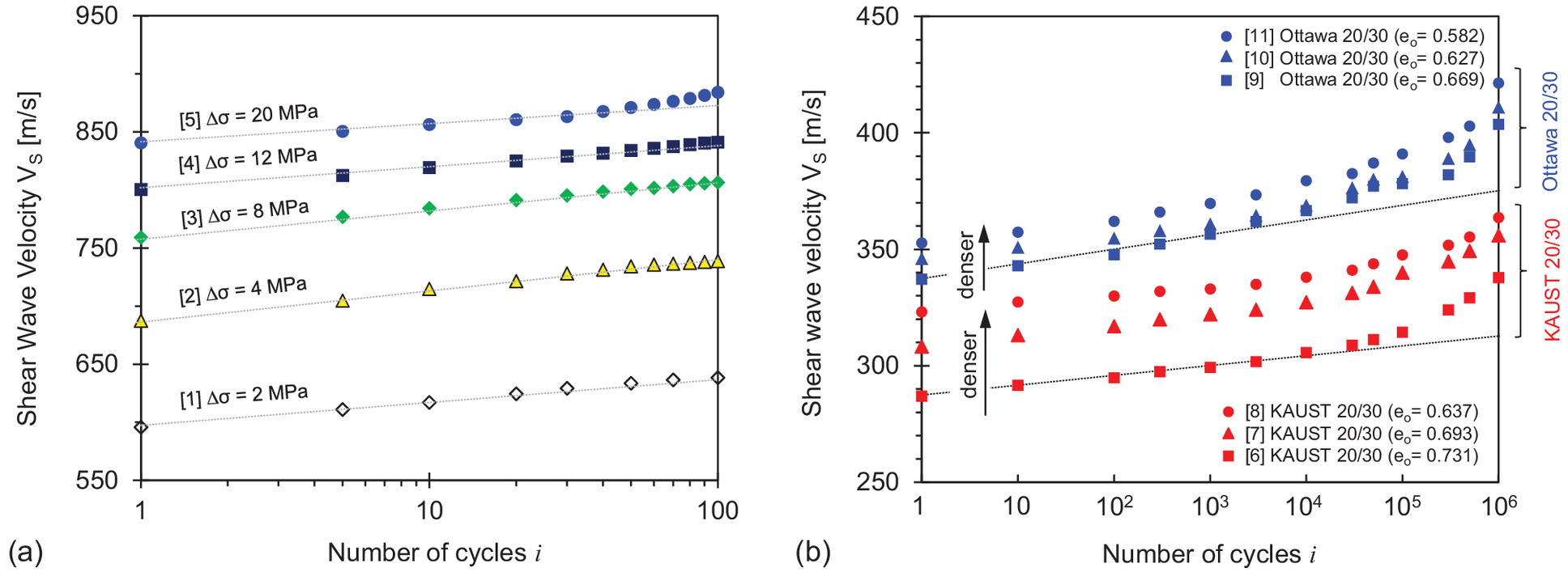
Fig. 11 presents shear wave signal cascades recorded throughout the loading history for high- and low-stress tests. Trends in shear wave velocity as a function of stress capture both contact behavior and fabric changes. The first arrival times decrease during the initial static loading stage in both cases. We pick first arrivals from amplified signals and disregard near-field effects [Criteria in Lee and Santamarina (2005)]. There are minor changes in travel time and wave form during repetitive loading cycles; thus, we use CODA wave analysis to determine accurate changes in travel times for different cycles in comparison with the signal at (Snieder 2006; Dai et al. 2013).
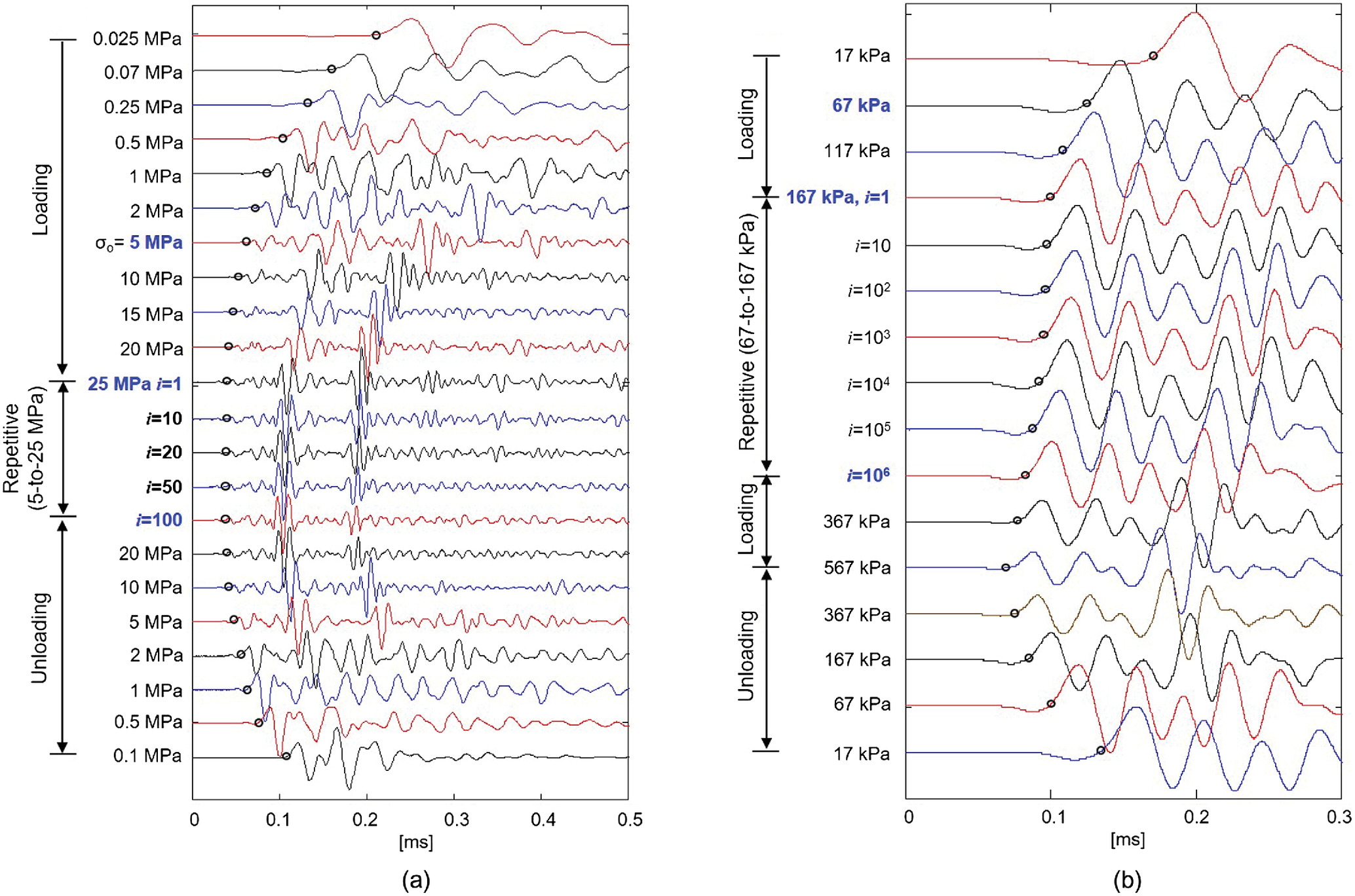
The shear wave velocity is a function of the mean effective stress in the polarization plane (Roesler 1979; Yu and Richart 1984; Santamarina et al. 2001). Values in Fig. 12 measured during static and repetitive loading stages exhibit a linear trend with stress in log–log scale; thereforewhere the factor is the shear wave velocity at 1 kPa, and the exponent represents the stress sensitivity of the shear wave velocity. The and values fitted to static loading trends in this study satisfy the inverse relationship observed for all soils (Cha et al. 2014).
(5)

High-stress data in Fig. 12(a) show a higher factor and a lower exponent when the stress level exceeds the yield stress . Furthermore, data in Fig. 12(b) show that sand specimens become stiffer, and the soil fabric becomes less sensitive to stress changes after low-stress cycles (higher factor and a lower exponent). Apparently, particle crushing and contact fretting enhance contacts, interparticle coordination, and fabric stability.
Finally, the shear wave velocity evolves linearly with during early loading cycles for both high- and low-stress tests (Fig. 13). However, shear wave velocity trends rise above the linear trend either due to high-stress [Fig. 13(a); Test 5 for after ] or a high number of cycles [Fig. 13(b) for ]. These observations suggest the emergence of grain degradation and pore filling associated with grain crushing, enhanced particle contacts, contact fretting, and asperity breakage as observed in terms of grain size (Fig. 2) and shape (Figs. 3 and 4), and in agreement with volume changes (Fig. 8).
Small Strain Shear Modulus versus Resilient Constrained Modulus
Pavement deformation and rutting reflects the evolution of vertical strains versus the number of load applications (Monismith 2004). The applied cyclic stress amplitude and the recoverable vertical strain define the resilient modulus (NCHRP 2004). In view of nondestructive pavement characterization, one may wonder about the relationship between the resilient modulus and the maximum stiffness inferred from elastic wave velocity measurements. Previous studies show that the stiffness ratio is about to 0.8 (Davich et al. 2004; Schuettpelz et al. 2010).
Similar concepts can be extended to all foundation systems subjected to repetitive loads. We investigate the ratio between the resilient constrained modulus extracted from 1D oedometric data and the maximum shear modulus computed from density and shear wave velocity . We compute the resilient constrained modulus as the ratio between the stress amplitude and the peak-to-peak strain in the th cycle where superscripts correspond to = loading when and = unloading at .
Fig. 14 shows the evolution of the stiffness ratio versus the number of cycles for high-stress and low-stress tests; for comparison, Fig. 14(b) presents previously published data. The stiffness ratio ranges between , and increases with the number of cycles, and higher ratios correspond to higher peak cyclic stress and lower densities.
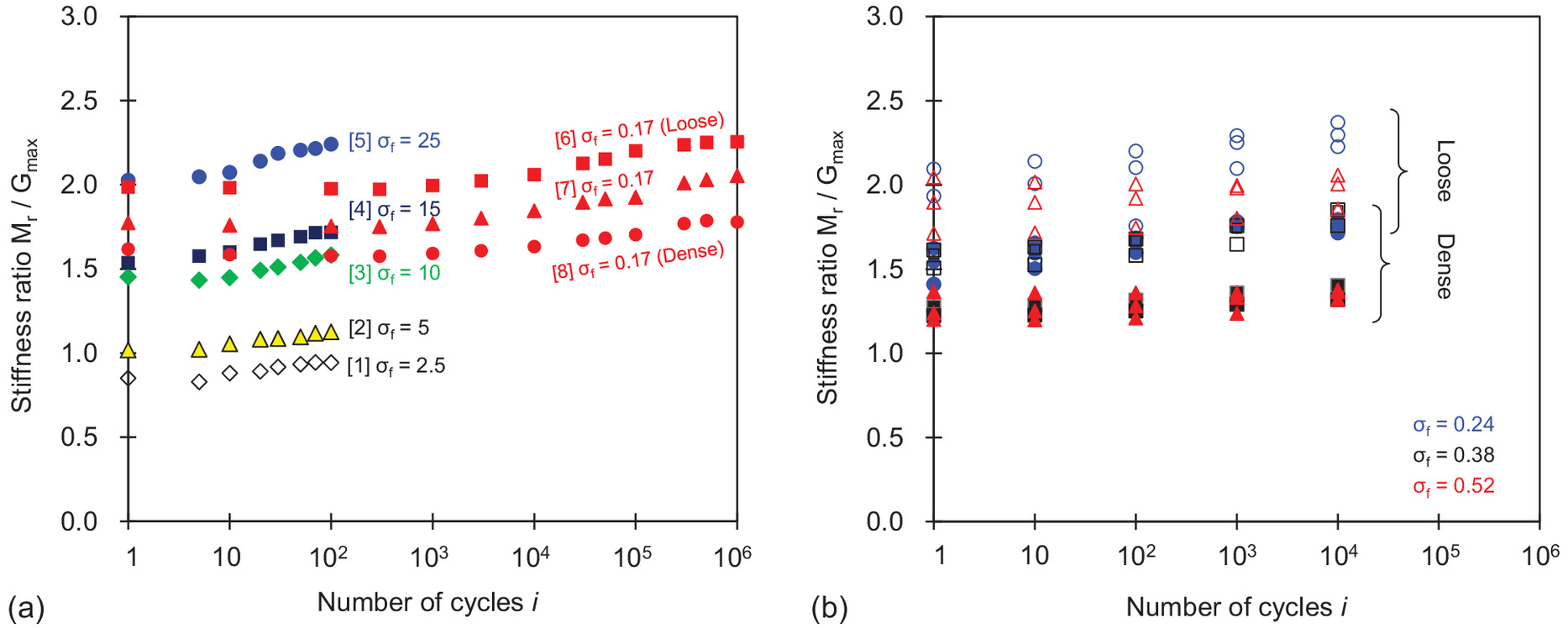
The peak-to-peak strain level is -to- in high-stress cycles, -to- in low-stress-stress cycle tests, and about in wave propagation measurements. Therefore, the resilient constrained modulus and the small-strain shear modulus involve different values of Poisson’s ratio. Similarly, the relationship between published values reported above and measured in this study require an intermediate-strain Poisson value to relate and , and a small-strain Poisson value to link to :
(6)
For and , the ratio is in agreement with the data.
Tipping Points: Deformation Mechanisms
While the modified hyperbolic function in Eq. (1) fits volumetric data well, “tipping points” are apparent in volumetric strain (Fig. 8) and shear wave velocity trends (Fig. 13) versus the number of cycles in logarithmic scale . Deviations become apparent within the first 20–30 cycles when the maximum stress exceeds the yield stress , or after cycles when the maximum cyclic stress (Refer to Wöhler’s curve; inset in Fig. 2).
Grain size distributions, optical photographs, and SEM images suggest different underlying mechanisms. High-stress cycles can produce fines that fill voids and participate in subsequent crushing events to produce even finer particles (Level III damage; Mesri and Vardhanabhuti 2009). On the other hand, sand contraction under a large number of low-stress cycles starts with the buckling of unstable granular columns together with particle sliding and rolling (Lambe and Whitman 1969; Omidvar et al. 2012); then, stress concentration at interparticle contacts leads to fatigue-induced asperity breakage and contact fretting (Djordjevic and Morrison 2006; Sadrekarimi and Olson 2010; Radjai et al. 1998).
Conclusions
This study explored the response of sands subjected to repetitive loading at both ends of the Wöhler’s curve, i.e., at a small number of high-stress cycles and for large number of low-stress cycles. Salient conclusions follows:
•
Higher stress cycles produce more fines. Particle degradation mechanisms vary with the maximum stress level. Sand particles subjected to high-stress cycles tend to split along cleavage planes to produce platy particles; the finer particles are flatter and more angular. On the other hand, surface abrasion, asperity breakage, and fretting prevail when sand grains experience a large number of low-stress cycles.
•
Sands subjected to repetitive loading reach asymptotic terminal void ratios . Its value is recovered by fitting the void ratio evolution versus the number of cycles using asymptotically correct functions. A modified hyperbolic function fits both high- and low-stress data well.
•
The empirical hyperbolic function used in this study adequately captures the evolving volumetric and stiffness response with the number of cycles. The use of such empirical functions within a hybrid numerical approach reduces numerical error and allows for efficient simulations that track the plastic strain accumulation during repetitive loading cycles.
•
The terminal void ratio for high-stress cycles depends on the peak cyclic stress due to crushing-dependent densification, and it can be smaller than when the peak cyclic stress approaches or exceeds the sand yield stress (measured in monotonic loading). On the other hand, the soil retains memory of the initial fabric even after a very large number of low-stress cycles, and the terminal void ratio for low-stress cycles correlates with the initial void ratio .
•
The change in void ratio from the initial state to the terminal void ratio () can be normalized by () to compare data for different sands and test conditions. Data show that the maximum change in relative density is a function of the sand initial relative density , the peak cyclic stress , and the stress amplitude . These results lead to simple yet robust strategies to estimate the maximum settlement for first-order engineering analyses.
•
Detailed analyses of volumetric and stiffness trends reveal tipping points and deviations from initial trends. In agreement with Wöhler’s fatigue, tipping points occur at a small number of high-stress cycles (as small as cycles when ) or after a large number of small-stress cycles ( cycles when ). Loosely packed sands experience tipping points at a lower number of cycles than dense sands due to higher contact forces for lower interparticle coordination.
•
The small-strain stiffness in monotonic loading increases with confinement and density. During repetitive loading, sands stiffen with the number of cycles to reflect increased interparticle coordination following crushing, as well as contact flattening due to asperity breakage and fretting.
•
The resilient constrained modulus evolves more rapidly than the shear modulus particularly during the earlier cycles when fabric changes are most pronounced; consequently, the stiffness ratio increases with the number of cycles. The stiffness ratio varies between for high-stress cycles and between for low-stress cycles. These values reflect the different strain levels involved in resilient modulus and wave velocity measurements and cannot be anticipated from theory of elasticity using a single Poisson’s ratio. The strong correlation between resilient modulus and shear modulus suggest the possible application of geophysical methods based on shear wave propagation to monitor geosystems subjected to repetitive loading cycles.
•
Repetitive loading studies under zero-lateral strain conditions allow us to anticipate the maximum change in relative density and the potential settlement a layer may experience when subjected to repetitive mechanical loads. Finally, 1D loading test results can be used to estimate the resilient constrained modulus for pavement design guideline.
Supplemental Materials
File (supplemental materials_jggefk.gteng-11153_park.pdf)
- Download
- 355.70 KB
Data Availability Statement
All data, models, and code generated or used during the study appear in the published article.
Acknowledgments
Support for this research was provided by the KAUST Endowment at King Abdullah University of Science and Technology. Gabrielle E. Abelskamp edited the manuscript.
References
Cha, M., J. C. Santamarina, H. S. Kim, and G. C. Cho. 2014. “Small-strain stiffness, shear-wave velocity, and soil compressibility.” J. Geotech. Geoenviron. Eng. 140 (10): 06014011. https://doi.org/10.1061/(ASCE)GT.1943-5606.0001157.
Cho, G. C., J. Dodds, and J. C. Santamarina. 2006. “Particle shape effects on packing density, stiffness, and strength: Natural and crushed sands.” J. Geotech. Geoenviron. Eng. 132 (5): 591–602. https://doi.org/10.1061/(ASCE)1090-0241(2006)132:5(591).
Chong, S. H., and J. C. Santamarina. 2016. “Sands subjected to vertical repetitive loading under zero lateral strain: Accumulation models, terminal densities, and settlement.” Can. Geotech. J. 53 (12): 2039–2046. https://doi.org/10.1139/cgj-2016-0032.
Coop, M. R., K. K. Sorensen, and T. B. Freitas. 2004. “Particle breakage during shearing of a carbonate sand.” Géotechnique 54 (3): 157–163. https://doi.org/10.1680/geot.2004.54.3.157.
da Fonseca, A. V., S. Rios, M. F. Amaral, and F. Panico. 2013. “Fatigue cyclic tests on artificially cemented soil.” Geotech. Test. J. 36 (2): 227–235.
Dai, S., F. Wuttke, and J. C. Santamarina. 2013. “Coda wave analysis to monitor processes in soils.” J. Geotech. Geoenviron. Eng. 139 (9): 1504–1511. https://doi.org/10.1061/(ASCE)GT.1943-5606.0000872.
D’Appolonia, D. J., and E. E. D’Appolonia. 1967. “Determination of the maximum density of cohesionless soils.” In Vol. 1 of Proc., 3rd Asian Regional Conf. on Soil Mechanics and Foundation Engineering, 266–268. Jerusalem, Israel: Jerusalem Academic Press.
Davich, P., J. Labuz, B. Guzina, and A. Drescher. 2004. Small strain and resilient modulus testing of granular soils. Minneapolis: Univ. of Minnesota.
Djordjevic, N., and R. Morrison. 2006. “Exploratory modelling of grinding pressure within a compressed particle bed.” Miner. Eng. 19 (10): 995–1004. https://doi.org/10.1016/j.mineng.2006.05.008.
Feda, J. 2002. “Notes on the effect of grain crushing on the granular soil behavior.” Eng. Geol. 63 (1): 93–98. https://doi.org/10.1016/S0013-7952(01)00072-2.
François, S., C. Karg, W. Haegeman, and G. Degrande. 2010. “A numerical model for foundation settlements due to deformation accumulation in granular soils under repeated small amplitude dynamic loading.” Int. J. Numer. Anal. Methods Geomech. 34 (3): 273–296. https://doi.org/10.1002/nag.807.
Guimaraes, M. S., J. R. Valdes, A. M. Palomino, and J. C. Santamarina. 2007. “Aggregate production: Fines generation during rock crushing.” Int. J. Miner. Process. 81 (4): 237–247. https://doi.org/10.1016/j.minpro.2006.08.004.
Hafez, A., Q. Liu, T. Finkbeiner, R. A. Alouhali, T. E. Moellendick, and J. C. Santamarina. 2021. “The effect of particle shape on discharge and clogging.” Sci. Rep. 11 (1): 1–11. https://doi.org/10.1038/s41598-021-82744-w.
Helland, P. E., P. H. Huang, and R. F. Diffendal. 1997. “SEM analysis of quartz sand grain surface textures indicates alluvial/colluvial origin of the Quaternary ‘glacial’ boulder clays at Huangshan (Yellow Mountain), East-Central China.” Quat. Res. 48 (2): 177–186. https://doi.org/10.1006/qres.1997.1916.
Indraratna, B., D. Ionescu, H. D. Christie, and R. N. Choudhury. 1997. “Compression and degradation of railway ballast under one-dimensional loading.” Aust. Geomech. J. 32 (4): 48–61.
Indraratna, B., H. Khabbaz, and J. Lackenby. 2003. “Behaviour of railway ballast under dynamic loads based on large-scale triaxial testing.” In AusRAIL PLUS 2003. Washington, DC: National Academies.
Indraratna, B., H. Khabbaz, W. Salim, and D. Christie. 2006. “Geotechnical properties of ballast and the role of geosynthetics in rail track stabilisation.” Proc. Inst. Civ. Eng. Ground Improv. 10 (3): 91–101. https://doi.org/10.1680/grim.2006.10.3.91.
Indraratna, B., and S. Nimbalkar. 2013. “Stress-strain degradation response of railway ballast stabilized with geosynthetics.” J. Geotech. Geoenviron. Eng. 139 (5): 684–700. https://doi.org/10.1061/(ASCE)GT.1943-5606.0000758.
Krumbein, W. C., and L. L. Sloss. 1963. Stratigraphy and sedimentation. 2nd ed. San Francisco: W. H. Freeman and Company.
Lade, P. V., and J. A. Yamamuro. 1996. “Undrained sand behavior in axisymmetric tests at high pressures.” J. Geotech. Eng. 122 (2): 120–129. https://doi.org/10.1061/(ASCE)0733-9410(1996)122:2(120).
Lambe, T. W., and R. V. Whitman. 1969. “Soil mechanics.” In Series in soil engineering. New York: Wiley.
Lee, J. S., and J. C. Santamarina. 2005. “Bender elements: Performance and signal interpretation.” J. Geotech. Geoenviron. Eng. 131 (9): 1063–1070. https://doi.org/10.1061/(ASCE)1090-0241(2005)131:9(1063).
Lee, K. L., and I. Farhoomand. 1967. “Compressibility and crushing of granular soil in anisotropic triaxial compression.” Can. Geotech. J. 4 (1): 68–86. https://doi.org/10.1139/t67-012.
Martinelli, G., P. Plescia, E. Tempesta, E. Paris, and F. Gallucci. 2020. “Fracture analysis of -quartz crystals subjected to shear stress.” Minerals 10 (10): 870. https://doi.org/10.3390/min10100870.
Masin, D. 2021. “Modelling non-linearity, small-strain stiffness and cyclic loading.” In Alert doctoral school 2021 constitutive modelling in geomaterials, edited by C. Tamagnini and D. Masin, 89–119. Prague, Czechia: Charles Univ.
McDowell, G. R. 1999. “Micromechanics of clastic soil.” In Proc., Int. Workshop on Soil Crushability, 138–157. Yamaguchi, Japan: Yamaguchi Univ.
Mesri, G., and B. Vardhanabhuti. 2009. “Compression of granular materials.” Can. Geotech. J. 46 (4): 369–392. https://doi.org/10.1139/T08-123.
Monismith, C. L. 2004. “Evolution of long-lasting asphalt pavement design methodology: A perspective.” In Proc., Int. Symp. of Design and Construction of Long Lasting Asphalt Pavements. Auburn, AL: Auburn Univ.
Narsilio, A., and J. C. Santamarina. 2008. “Terminal densities.” Géotechnique 58 (8): 669–674.
NCHRP (National Cooperative Highway Research Program). 2004. Guide for mechanistic-empirical design of new and rehabilitated pavement structures. Washington, DC: NCHRP.
Niemunis, A., T. Wichtmann, and T. Triantafyllidis. 2005. “A high-cycle accumulation model for sand.” Comput. Geotech. 32 (4): 245–263. https://doi.org/10.1016/j.compgeo.2005.03.002.
Okochi, Y., and F. Tatsuoka. 1984. “Some factors affecting ko values of sand measured in triaxial cell.” Soils Found. 24 (3): 52–68. https://doi.org/10.3208/sandf1972.24.3_52.
Omidvar, M., M. Iskander, and S. Bless. 2012. “Stress-strain behavior of sand at high strain rates.” Int. J. Impact Eng. 49 (Nov): 192–213. https://doi.org/10.1016/j.ijimpeng.2012.03.004.
Park, J., and J. C. Santamarina. 2019. “Sand response to a large number of loading cycles under zero-lateral strain conditions: Evolution of void ratio and small strain stiffness.” Géotechnique 69 (6): 501–513. https://doi.org/10.1680/jgeot.17.P.124.
Pasten, C., H. Shin, and J. C. Santamarina. 2014. “Long-term foundation response to repetitive loading.” J. Geotech. Geoenviron. Eng. 140 (4): 04013036. https://doi.org/10.1061/(ASCE)GT.1943-5606.0001052.
Radjai, F., D. E. Wolf, M. Jean, and J. J. Moreau. 1998. “Bimodal character of stress transmission in granular packings.” Phys. Rev. Lett. 80 (1): 61–64. https://doi.org/10.1103/PhysRevLett.80.61.
Roesler, S. K. 1979. “Anisotropic shear modulus due to stress anisotropy.” J. Geotech. Eng. 105 (7): 871–880. https://doi.org/10.1061/AJGEB6.0000835.
Sadrekarimi, A., and S. M. Olson. 2010. “Particle damage observed in ring shear tests on sands.” Can. Geotech. J. 47 (5): 497–515. https://doi.org/10.1139/T09-117.
Santamarina, J. C., and D. Fratta. 2005. Discrete signals and inverse problems: An introduction for engineers and scientists. New York: Wiley.
Santamarina, J. C., K. A. Klein, and M. A. Fam. 2001. Soils and waves: Particulate materials behavior, characterization and process monitoring. New York: Wiley.
Schuettpelz, C. C., D. Fratta, and T. B. Edil. 2010. “Mechanistic corrections for determining the resilient modulus of base course materials based on elastic wave measurements.” J. Geotech. Geoenviron. Eng. 136 (8): 1086–1094. https://doi.org/10.1061/(ASCE)GT.1943-5606.0000329.
Snieder, R. 2006. “The theory of coda wave interferometry.” Pure Appl. Geophys. 163 (2–3): 455–473. https://doi.org/10.1007/s00024-005-0026-6.
Suiker, A. S., E. T. Selig, and R. Frenkel. 2005. “Static and cyclic triaxial testing of ballast and subballast.” J. Geotech. Geoenviron. Eng. 131 (6): 771–782. https://doi.org/10.1061/(ASCE)1090-0241(2005)131:6(771).
Suiker, A. S. J., and R. de Borst. 2003. “A numerical model for the cyclic deterioration of railway tracks.” Int. J. Numer. Methods Eng. 57 (4): 441–470. https://doi.org/10.1002/nme.683.
Uygar, E., and A. G. Doven. 2006. “Monotonic and cyclic oedometer tests on sand at high stress levels.” Granular Matter 8 (1): 19–26. https://doi.org/10.1007/s10035-005-0216-z.
Valdes, J. R., and J. C. Santamarina. 2006. “Particle clogging in radial flow: Microscale mechanisms.” Soc. Pet. Eng. J. 11 (2): 193–198. https://doi.org/10.2118/88819-PA.
Valdes, J. R., and J. C. Santamarina. 2008. “Clogging: Bridge formation and vibration-based destabilization.” Can. Geotech. J. 45 (2): 177–184. https://doi.org/10.1139/T07-088.
Werkmeister, S. 2003. “Permanent deformation behaviour of unbound granular materials in pavement constructions.” Ph.D. thesis, Dept. of Civil Engineering, Technischen Universität.
Werkmeister, S., A. R. Dawson, and F. Wellner. 2005. “Permanent deformation behaviour of granular materials.” Road Mater. Pavement Des. 6 (1): 31–51. https://doi.org/10.1080/14680629.2005.9689998.
Wichtmann, T. 2005. “Explicit accumulation model for non-cohesive soils under cyclic loading.” Ph.D. thesis, Institute for Soil Mechanics and Foundation Engineering, Ruhr Univ. Bochum.
Yu, P., and F. E. Richart Jr. 1984. “Stress ratio effects on shear modulus of dry sands.” J. Geotech. Eng. 110 (3): 331–345. https://doi.org/10.1061/(ASCE)0733-9410(1984)110:3(331).
Zhu, Z., F. Zhang, J. C. Dupla, J. Canou, and E. Foerster. 2020. “Investigation on the undrained shear strength of loose sand with added materials at various mean diameter ratios.” Soil Dyn. Earthquake Eng. 137 (Oct): 106276. https://doi.org/10.1016/j.soildyn.2020.106276.
Zhu, Z., F. Zhang, J. C. Dupla, J. Canou, E. Foerster, and Q. Peng. 2021. “Assessment of tamping-based specimen preparation methods on static liquefaction of loose silty sand.” Soil Dyn. Earthquake Eng. 143 (Apr): 106592. https://doi.org/10.1016/j.soildyn.2021.106592.
Information & Authors
Information
Published In

Journal of Geotechnical and Geoenvironmental Engineering
Volume 149 • Issue 11 • November 2023
Copyright
This work is made available under the terms of the Creative Commons Attribution 4.0 International license, https://creativecommons.org/licenses/by/4.0/.
History
Received: Jul 3, 2022
Accepted: Mar 31, 2023
Published online: Sep 14, 2023
Published in print: Nov 1, 2023
Discussion open until: Feb 14, 2024
ASCE Technical Topics:
- Clays
- Continuum mechanics
- Data analysis
- Design (by type)
- Dynamics (solid mechanics)
- Engineering fundamentals
- Engineering mechanics
- Fatigue (material)
- Geomechanics
- Geotechnical engineering
- Granular soils
- Load factors
- Material mechanics
- Material properties
- Materials engineering
- Mechanical properties
- Methodology (by type)
- Research methods (by type)
- Rock mechanics
- Seismic waves
- Shear modulus
- Shear waves
- Soil mechanics
- Soils (by type)
- Solid mechanics
- Stress (by type)
- Structural analysis
- Structural design
- Structural engineering
- Void ratio
- Voids
- Waves (mechanics)
- Yield stress
Authors
Metrics & Citations
Metrics
Citations
Download citation
If you have the appropriate software installed, you can download article citation data to the citation manager of your choice. Simply select your manager software from the list below and click Download.
Cited by
- Carlos D. Rodriguez-Hernandez, Junghee Park, Heriberto Echezuria, J. Carlos Santamarina, Volume Contraction and Reduction in Hydraulic Conductivity during Particle Crushing, Journal of Geotechnical and Geoenvironmental Engineering, 10.1061/JGGEFK.GTENG-12234, 150, 6, (2024).