Optimized Hybrid Carbon-Glass Textile-Reinforced Mortar for Flexural and Shear Strengthening of RC Members
Publication: Journal of Composites for Construction
Volume 28, Issue 1
Abstract
The open mesh textile reinforcements used today in textile-reinforced mortar (TRM) strengthening applications are composed of identical fiber rovings in both orthogonal directions, regardless of the type of application. However, for reinforced concrete (RC) members, such as beams and columns, where fibers are utilized in one main direction, such textile geometry can lead to ineffective and excessive use of raw materials and, therefore, uneconomic design. This paper experimentally investigates the use of hybrid textile reinforcement for flexural and shear strengthening in 22 RC beams. Four types of hybrid textiles were designed and manufactured to allow for the environmentally friendly and cost-efficient use of the fibers. Expensive high-strength carbon and weaker glass fibers were used in the main and secondary directions, respectively. Hybrid carbon–glass textiles, which are composed of weaker glass fiber rovings with larger spacings in the secondary direction, showed similar effectiveness with the standard carbon textiles with 50%–50% weight distribution per direction. A cost estimation revealed that massive savings on raw materials can be achieved when hybrid layouts are used instead of conventional textiles. Therefore, the results of this paper could provide a new scope for the optimization of current TRM systems for various retrofitting applications and might assist in the development of a more economical, environmentally friendly, and balanced design of textile reinforcements.
Introduction and Background
Structural retrofitting of existing structures is becoming more important due to: (1) their aging and degradation of the material’s mechanical properties; (2) the accumulation of damage from previous events (e.g., moderate earthquakes and fires); (3) their poor initial design combined with the requirements to comply with modern standards (e.g., Eurocodes); or (4) any structural interventions that result in structural members of inadequate resistance to withstand the redistributed forces. In addition to structural upgrading, energy retrofitting of low energy performance buildings is becoming a key measure to cope with climate change (e.g., the Renovation Wave building initiative as a part of the European Green Deal). Therefore, structural retrofitting methods should be selected to promote sustainability, resilience, cost-effectiveness, and circularity of materials when possible. Therefore, textile-reinforced mortar (TRM) was introduced in the early twenty-first century as an inorganic matrix composite material that was suitable for structural retrofitting applications.
In addition, TRM is known as fabric-reinforced cementitious matrix (FRCM) and belongs to a relatively new generation of composite materials. It was introduced approximately two decades ago (Brückner et al. 2006; Triantafillou et al. 2006; Bournas et al. 2007) and has been used in a wide range of applications in strengthening and seismic retrofitting of reinforced concrete (RC) (e.g., Awani et al. 2017; Koutas et al. 2019; Gkournelos et al. 2021) and masonry structures (e.g., Kariou et al. 2018; Kouris and Triantafillou 2018; Pohoryles and Bournas 2020; Filippou et al. 2022; Gkournelos et al. 2022b).
TRMs were originally developed as an alternative to the well-known fiber-reinforced polymer (FRP) composites to overcome some of their drawbacks. Compared with FRPs, TRM systems: (1) have better resistance at high temperatures or under fire conditions (Tetta and Bournas 2016; Raoof and Bournas 2017; Triantafillou et al. 2017; Sui et al. 2020; Cerniauskas et al. 2020); (2) cost less due to the lower cost of the matrix material; (3) can be applied under low temperature conditions and to wet surfaces; and (4) are air permeable, which allows the structural elements to “breathe”. Research studies that focused on direct comparisons between FRP and TRM systems have demonstrated that TRMs perform comparably with FRPs provided that a good bond between the matrix, fiber, and substrate is achieved (Bournas et al. 2007; Al-Salloum et al. 2011; Tetta et al. 2015; Raoof et al. 2017).
An additional benefit of TRMs is that they can be easily integrated with standard thermal insulation systems. Therefore, they could become a holistic and cost-efficient repair solution to improve the structural behavior and the energy consumption of existing buildings (e.g., Triantafillou et al. 2017; Bournas 2018; Gkournelos et al. 2019; Pohoryles et al. 2020; Baek et al. 2022; Furtado et al. 2022).
A TRM system consists of two parts: (1) the textile reinforcement; and (2) the mortar that serves as the matrix of the composite and the binding material between the TRM overlay and the substrate. Typically, cement-based mortars are used as inorganic matrix materials, which are sometimes mixed with short polypropylene fibers to control plastic shrinkage. In addition, mortars based on lime or alkali-activated materials (e.g., geopolymers) can be used to overcome the compatibility issues (i.e., in cultural heritage) or due to environmental issues that are associated with the carbon footprint that is generated during the production of cementitious materials (e.g., Dalalbashi et al. 2019; Signorini et al. 2019; Longo et al. 2020; Arce et al. 2022; Skyrianou et al. 2022; Cholostiakow et al. 2023). Limited experimental studies (D’Ambrisi and Focacci 2011; Elsanadedy et al. 2013; Koutas and Papakonstantinou 2021) have shown that different mortar types can have a strong influence on the flexural capacity of retrofitted beams and even alter the failure modes.
In contrast to FRP systems, where unidirectional or bidirectional fabrics with continuous fibers are used, the fabrics in TRM systems are composed of continuous fibers in at least two directions with perforations to enhance the bond between the matrix and the fibers. Therefore, in TRM systems, open mesh fabrics are used, which are composed of fiber rovings at certain spaces. Each roving consists of hundreds of high-strength filaments made typically from carbon, glass, polyparaphenylene benzobisoxazole, or basalt. Recently, fabrics that are made of natural fibers have been studied as alternative low-cost and ecofriendly solutions (e.g., Ferrara et al. 2020; Gkournelos et al. 2022a; Trochoutsou et al. 2022). It is assumed that fibers in the main direction of the textile, called the warp direction, carry the tensile stresses and the fibers in the secondary direction, called the weft direction, contribute to the structural stability of the textile during application and to the development of a mechanical interlock mechanism.
Today, many TRM systems are commercially available; however, they have not been standardized. In addition, an optimized design of the textile reinforcement layout per application needs to be reached. With a few exceptions, most commercially available open mesh textiles are composed of fiber rovings of the same material in two orthogonal directions with a 50%–50% weight distribution in the warp and weft directions. These balanced textiles could be suitable for applications where structural members are subjected to biaxial stresses and both directions are effectively utilized, such as unreinforced masonry walls, masonry infill walls in RC frames, or two-way RC slabs (e.g., Koutas et al. 2014; Koutas and Bournas 2017, 2019). However, for applications where the fibers work in one of the directions, for instance, in beams or columns that are subjected to bending and shear, such a design becomes uneconomical because the warp and the weft fibers will not contribute equally to the additional capacity that is offered by the TRM overlay. Therefore, most commercially available textiles are general-purpose textiles that have not been optimized for specific applications.
A major barrier to the development of a more effective TRM design is the lack of a proper understanding of how the textile geometry can alter the performance of the TRM system. In addition, the high cost of high-strength materials, such as carbon fibers, often prevents designers from choosing TRMs as a preferable repair solution. A considerable amount of research has been carried out to study the performance of different types of textiles. However, to the best of the authors’ knowledge, no comprehensive research study has focused on the effect of the textile layout on the TRM performance. In particular, no experimental evidence exists on the isolated effect of the fiber material (e.g., carbon versus glass) or the textile geometry, such as the roving spacing (e.g., small versus large mesh size) on the effectiveness of the TRM for the same materials’ weight per direction. A single experimental study (Tetta et al. 2018a) indicated that carbon fiber textiles with different geometries could perform differently in beam elements with TRM jackets. Therefore, the contribution of the textile along their warp and weft directions can vary with the textiles’ geometry and warrants further investigation.
A rational solution to address this issue is to use an optimized TRM design when strengthening linear RC elements (e.g., beams and columns), which are composed of different fibers in each orthogonal direction. There are stronger fibers (e.g., carbon) in the warp direction and weaker fibers (e.g., glass and polypropylene) in the secondary weft direction. Recent studies explored the use of these hybrid carbon–glass fiber textiles for TRM strengthening applications on concrete substrates (e.g., Ebead et al. 2017; Liu et al. 2017; Akbari Hadad et al. 2018; Elghazy et al. 2018a, b; Signorini et al. 2019; Hadad et al. 2020); however, none discussed the effect of the textiles’ geometry on various strengthening configurations. Therefore, no practical conclusion on the design could be formed.
Although the textile reinforcement industry is quite young (since the early 2000s), the versatility and performance of TRM systems has been quickly recognized by the research community and industry. Recently, a large number of research studies have been carried out and a few design guidelines are now available [e.g., ACI 549.4R-13 (ACI 2013), RILEM TC 234-DUC (RILEM 2016), fib bulletin 103 (fib 2022), and CNR-DT 215/2018 (NRC 2018)]. Moreover, the first real-world TRM applications have recently been documented (Bournas 2016). Precise global market data is not available; the fast pace of the research and the increasing number of TRM systems that are offered in the market indicate that the potential of this field is vast and will keep growing in the future. The TRM industry is developing rapidly, with new products and solutions being proposed, which include different types of textiles and binders or, as mentioned previously, integrated structural and thermal retrofitting systems. Therefore, optimized and more effective TRM systems could be in demand.
However, the role of the textiles’ layout is not well understood, and most of the TRM systems currently available in the market are composed of general-purpose textiles that are not optimized for certain strengthening applications. This paper goes beyond the current state-of-the-art and, for the first time, investigates the effectiveness of various hybrid textile geometries as a TRM retrofitting system for concrete beam elements, to the best of the authors’ knowledge. Four fit-to-purpose carbon–glass hybrid textile meshes are manufactured by an industrial textile company to develop more cost-efficient flexural and shear strengthening solutions for RC beams. In total, 22 half-scale rectangular RC beams strengthened with various hybrid TRM configurations are tested to determine the effect of the textile layout on the strengthening performance of the TRM system. This hybrid solution could provide a comparable strengthening capacity as the standard textiles and dramatically reduce the costs of the textile fabric. The findings of this paper are timely and could contribute to the development of more optimized strengthening solutions for deteriorated building stock.
Experimental Program
Test Specimens and Investigated Parameters
All tested specimens are listed in Table 1. Specimens are grouped into two series:(1) FL; and (2) SH, which correspond to flexure and shear tests, respectively. The first 11 beams were designed to fail in bending (FL_Series), and the remaining 11 were designed to fail in shear (SH_Series). All 22 beams had the same geometry (102 × 203 × 1,675 mm) (width × height × length), with an effective depth of 177 mm. In each group, one beam was tested without strengthening and was a reference specimen, and 10 were tested after they were retrofitted with different strengthening configurations. In each series, two beams were strengthened with a commercial nonhybrid carbon fiber textile (one and three layers, respectively), which has been extensively used in previous research studies by the authors (Tetta et al. 2015, 2018a; Tetta and Bournas 2016; Raoof et al. 2017) and served as conventionally strengthened reference specimens. In the other elements, various hybrid textile layouts were applied. Of note, the results for three out of the 11 beams per testing series (one reference and two beams with the commercial textile) were previously published by Tetta et al. (2015) and Raoof et al. (2017). The hybrid textiles were composed of carbon and glass fiber rovings in the main (warp) and secondary (weft) directions, respectively. The quantity of carbon fibers in the warp direction remained constant in all the retrofitted beams; therefore, the individual contribution of the secondary direction could be analyzed. The main investigated parameters were the same for both testing groups and included: (1) the number of TRM layers; and (2) the textile geometry with a specific focus on the role of the spacing of the fiber rovings in both orthogonal directions. The labeling of the beams referred to the strengthening layout and type of test. For instance, the control beam that was designed to fail in flexure or shear and without any retrofitting was CON, the specimen that was strengthened in flexure with one layer of the commercial textile was M1_C, and the beam that was strengthened in shear with three layers of the H10 × 20 hybrid textile was SH_H10 × 20_3. Where H = hybrid and was followed by the size of the grid and the number of textile layers. The size of the grid was determined by the spacing of the carbon fiber rovings in the main direction and the spacing of the glass fiber rovings in the secondary direction. Therefore, the reinforcement ratio in the main direction remained constant for the specimen groups with the same number of TRM layers (Table 1), which allowed for a direct comparison of specimens with different textile geometries.
| Specimen | Textile reinforcement ratio [ρf (%)] | Concrete compressive strength [fc (MPa)] | Mortar compressive strength [fmc (MPa)] | Mortar flexural strength [fmt,fl (MPa)] |
|---|---|---|---|---|
| FL_Series (flexural strengthening) | ||||
| CONa | — | 21.7 | — | — |
| M1_Ca | 0.048 | 19.9 | 39.2 | 9.8 |
| M3_Ca | 0.143 | 19.9 | 39.2 | 9.8 |
| FL_H10 × 20_1 | 0.048 | 21.5 | 35.6 | 8.1 |
| FL_H10 × 20_3 | 0.143 | 21.5 | 35.6 | 8.1 |
| FL_H10 × 40_1 | 0.048 | 21.5 | 35.6 | 8.1 |
| FL_H10 × 40_3 | 0.143 | 21.5 | 35.6 | 8.1 |
| FL_H20 × 20_1 | 0.048 | 20.8 | 37.3 | 8.7 |
| FL_H20 × 20_3 | 0.143 | 20.8 | 37.3 | 8.7 |
| FL_H20 × 40_1 | 0.048 | 20.8 | 37.3 | 8.7 |
| FL_H20 × 40_3 | 0.143 | 20.8 | 37.3 | 8.7 |
| SH_Series (shear strengthening) | ||||
| CONb | — | 21.6 | — | — |
| UW_M1b | 0.19 | 23.8 | 31.1 | 10.3 |
| UW_M3b | 0.56 | 22.6 | 26.9 | 8.64 |
| SH_H10 × 20_1 | 0.19 | 21.4 | 46.6 | 9.46 |
| SH_H10 × 20_3 | 0.56 | 21.4 | 46.6 | 9.46 |
| SH_H10 × 40_1 | 0.19 | 21.4 | 46.6 | 9.46 |
| SH_H10 × 40_3 | 0.56 | 21.4 | 46.6 | 9.46 |
| SH_H20 × 20_1 | 0.19 | 20.1 | 32.8 | 7.80 |
| SH_H20 × 20_3 | 0.56 | 20.1 | 32.8 | 7.80 |
| SH_H20 × 40_1 | 0.19 | 20.1 | 32.8 | 7.80 |
| SH_H20 × 40_3 | 0.56 | 20.1 | 32.8 | 7.80 |
Flexure-Critical Specimens (FL_Series)
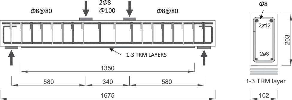
The geometry and layouts of the steel and TRM reinforcements for the beams that were tested in bending are shown in Fig. 1. All beams were designed with a low longitudinal reinforcement ratio (ρs = 0.56%) to simulate flexural-deficient beams. The longitudinal steel reinforcement consisted of two 8 mm deformed steel bars in the tension zone and two 12 mm deformed steel bars in the compression zone. The shear reinforcement was composed of 8 mm steel stirrups at 80 mm spacing in the shear span regions and two 8 mm stirrups in the shear-free zone. The design of the beams ensured flexural failure up to a sevenfold enhancement in the flexural capacity of the beam after strengthening. The TRM retrofitting overlay consisted of one or three layers of textile mesh reinforcement that was embedded in the cementitious matrix. The bonded length of the composite layers was 1,350 mm, and their width was equal to the width of the beam. Of note, apart from the TRM–concrete interface bond, no additional anchorage was provided in the TRM composites.
Shear-Critical Specimens (SH_Series)
The geometry and layout of the steel and TRM reinforcements for the beams that were tested in shear are shown in Fig. 2. The longitudinal steel reinforcement consisted of two 16 mm steel bars in the tension and two 10 mm bars in the compression zone. The shorter shear span, which was designed to fail in shear, had no shear reinforcement. The remaining beam length was reinforced in shear with 8 mm steel stirrups at 75 mm spacings.
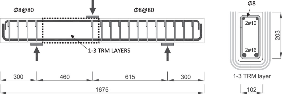
The beams were strengthened with three-sided TRM jackets (U-jackets), as previous tests showed that this strengthening layout was practical and effectively utilized the potential of TRM reinforcement (Tetta et al. 2015). Similar to the FL Series, in the SH Series, the TRM was applied in one or three layers. However, only the 460 mm shear span between the loading and bearing plates was strengthened, as shown by the dotted region in Fig. 2.
Materials
Concrete and Steel Reinforcement
The concrete compressive and splitting tensile strengths were determined with standard 150 × 300 concrete cylinders on the day of testing and are summarized in Table 1. Ribbed steel rebars were used as internal flexural and shear reinforcements. The mechanical properties were obtained from tensile tests on three bar samples for each diameter and are presented in Table 2.
| Rebar diameter (mm) | Yield stress [fy (MPa)] | Ultimate strength [fu (MPa)] | Ultimate strain [ɛy (%)] |
|---|---|---|---|
| 8 | 569 | 631 | 7.9 |
| 10 | 552 | 593 | 8.4 |
| 12 | 561 | 637 | 12.8 |
| 16 | 547 | 602 | 9.9 |
Strengthening Materials
Textile Reinforcement and Matrix Properties
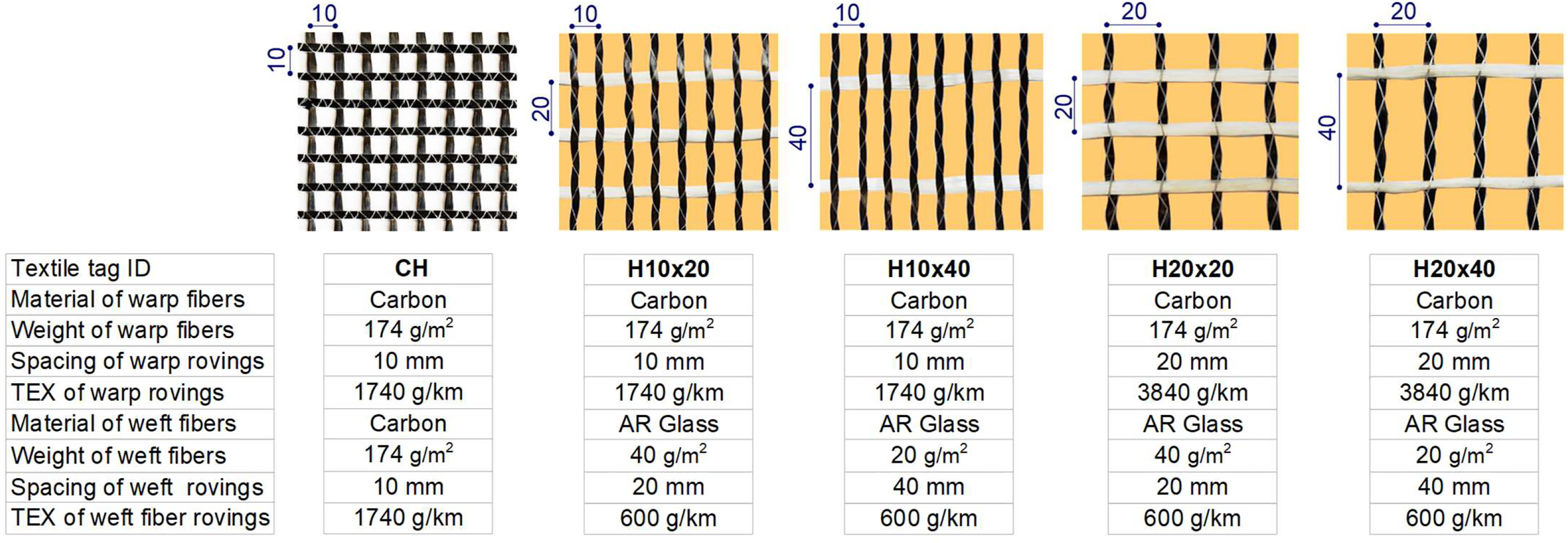
The geometry and properties of all five textiles are shown in Fig. 3. The first textile (CH) was a commercial uncoated carbon textile that is available in the market and served as a reference. The remaining four hybrid textiles were designed with the same amount of carbon fibers in the warp direction (174 g/m2). However, the warp direction fiber rovings were distributed at two different spacings (e.g., 10 and 20 mm spacing denoted by H10 and H20, respectively). Therefore, the TEX (gramms per running kilometer per fiber roving) of the warp fiber rovings was 1,740 g/km for H10 textiles and 3,840 g/km for H20 textiles, because the latter had two times more fibers per roving. The glass fiber rovings in the secondary direction were composed of the same TEX (600 g/km). However, they were distributed at two different spacings (20 and 40 mm denoted by ×20 and ×40, respectively). Therefore, the weight of glass fibers per direction was 40 g/m2 for ×20 textiles and 20 g/m2 for ×40. Polypropylene fibers were used to stitch the fiber rovings in place and underwent a standard thermosetting procedure. All textiles were uncoated. Of note, all hybrid textiles were manufactured by a UK industrial firm under the guidance of the first and third authors and followed specific instructions. The firm could fabricate two-dimensional open mesh textiles with its existing facilities and standard equipment without any major modifications. Therefore, such amendments to the textiles’ structure could be easily implemented by other technical textiles manufacturers. To date, no manufacturing-related limitations on the use of hybrid textiles exist; therefore, introducing novel and optimized textiles is technically feasible.
The main mechanical properties of the reference and hybrid textiles in the main (warp) direction were determined experimentally and are presented in Table 3. The tensile strength, strain, and elastic modulus for each textile were determined on three 50 × 500 mm bare textile samples.
| Textile | Tensile strengtha [ftu (MPa)] | Ultimate tensile straina [ɛtu (%)] | Modulus of elasticitya [Ef,exp (GPa)] |
|---|---|---|---|
| CH | 1,465.1 (95) | 0.792 (0.05) | 175.7 (21) |
| H10 × 20 | 1,456.0 (111) | 0.700 (0.04) | 208.0 (18) |
| H10 × 40 | 1,340.1 (95) | 0.652 (0.06) | 205.5 (20) |
| H20 × 20 | 1,549.3 (120) | 0.817 (0.05) | 189.6 (19) |
| H20 × 40 | 1,562.1 (123) | 0.934 (0.07) | 167.2 (13) |
a
Standard deviation in parenthesis.
The mortar that was used in the TRM composite served as the matrix material and acted as the adhesive between the TRM composite and the concrete substrate. The mortar consisted of two components: (1) the dry component (called the dry binder); and (2) water. The components were mixed at a ratio of 0.23:1.00 (water:dry binder ratio) to achieve good workability. According to the manufacturer’s datasheets, the dry binder consisted of ordinary Portland cement and polymers (as dry powder) at a ratio of 8:1 by weight. There was no activation of any component before mixing. The flexural and compressive strengths of the mortar were tested on the same day as the beams with standard 40 × 40 × 160 mm prisms that conformed to EN 1015-11 (CEN 2019). The main results are listed in Table 1.
Composite Material Properties
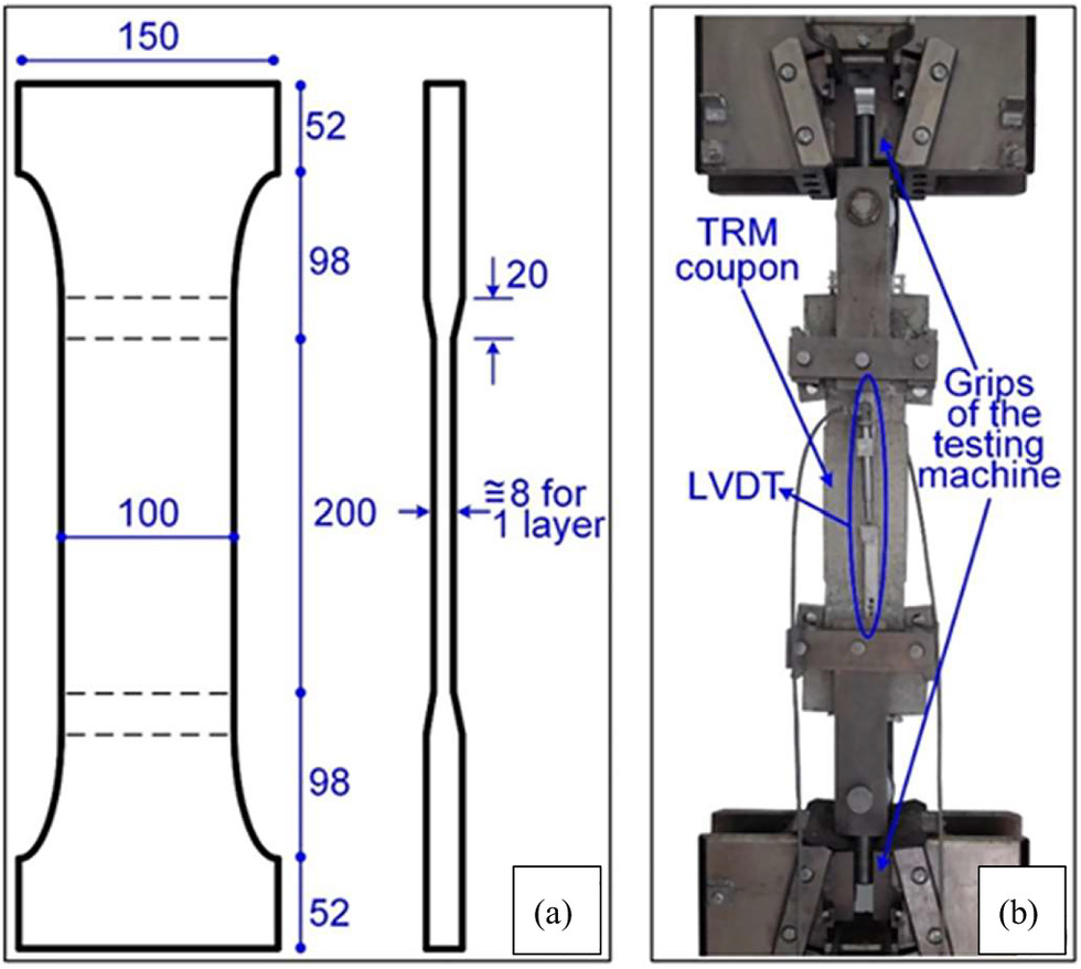
The mechanical characteristics of the TRM composite for all textile layouts were determined experimentally on coupon specimens [Fig. 4(a)]. Two specimens per strengthening layout were tested to account for the material’s variability. Each specimen was composed of one TRM layer. Two TRM layers were only placed in the end regions to promote failure in the middle region. In the end regions, textiles were coated with epoxy resin for extra bonding. The strain in the coupons was measured with two linear variable differential transformers (LVDTs) that were fixed in the center of the specimen at 200 mm base length [Fig. 4(b)]. Among various test methods that were suitable to determine the tensile properties of the TRM composites, the curved flange method was selected in this paper, with coupon specimens that had dumbbell geometry [Fig. 4(a)]. More details on the various tensile test setups and their effect on the results are provided by D’Antino and Papanicolaou (2018) and Focacci et al. (2022).
The stress–strain curves and the main test results for all coupon samples are shown in Fig. 5. The samples that were subjected to uniaxial tension showed a response that was typical for TRM composites: (1) a stiff elastic response during the initial stage of loading until cracking in the mortar; and (2) a macroscopically linear response with reduced stiffness due to the development of cracks in the mortar until brittle failure occurred. The coupons failed due to the fibers’ rupture in the central region of the specimens, which was within the gauge length.
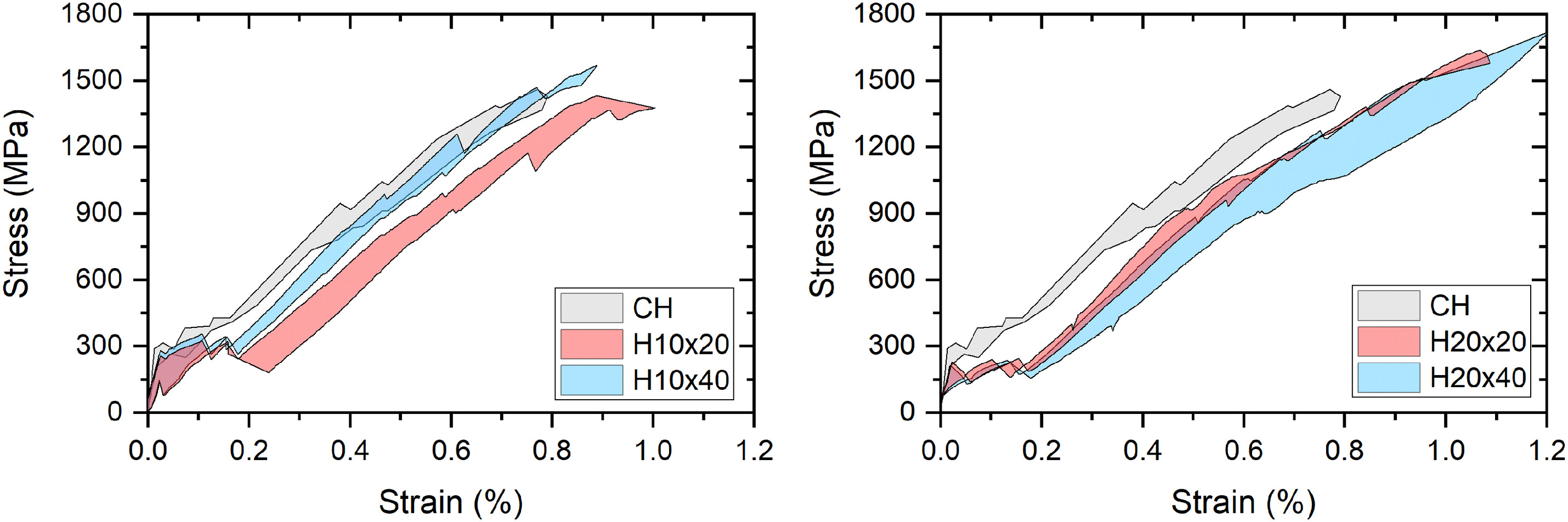
Table 4 reports the mean values of the ultimate tensile stress (ffu), ultimate strain (ɛfu), and modulus of elasticity (Ef,exp). The ultimate tensile stress that corresponded to the TRM tensile strength was calculated by dividing the recorded peak load by the area of the textile’s fibers in the loading direction. The ultimate strain corresponded to the ultimate stress. Finally, the modulus of elasticity was determined as the secant modulus of the stress–strain curve during the second stage of the coupon’s response, which was equal to the slope of the line that connected the point of first cracking with the point of ultimate stress (Raoof et al. 2017).
| Composite material | Tensile strengtha [ffu (MPa)] | Ultimate tensile straina [ɛfu (%)] | Modulus of elasticitya [Ef,exp (GPa)] |
|---|---|---|---|
| CH | 1,417.9 (86) | 0.784 (0.13) | 168.7 (5) |
| H10 × 20 | 1,404.7 (126) | 0.946 (0.12) | 161.6 (10) |
| H10 × 40 | 1,523.7 (149) | 0.873 (0.08) | 175.7 (10) |
| H20 × 20 | 1,564.5 (139) | 0.996 (0.07) | 165.9 (7) |
| H20 × 40 | 1,610.7 (155) | 1.082 (0.13) | 159.0 (12) |
a
Standard deviation in parenthesis.
Strengthening Procedure
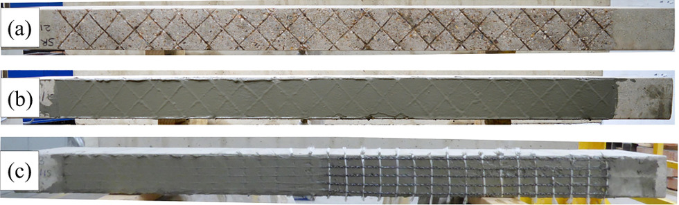
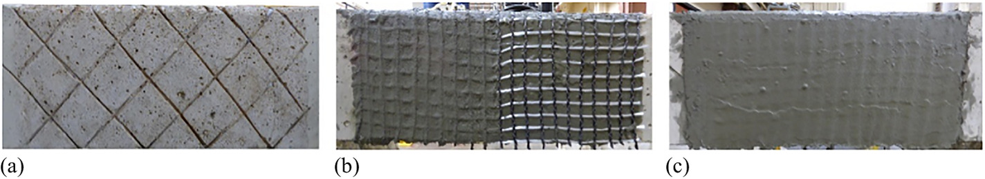
To enhance the bond between the concrete and TRM layers, the concrete surfaces were roughened by cutting 3 mm grooves on a 50 mm grid [Figs. 6(a) and 7(a)]. Subsequently, dust and debris were cleaned from the concrete with compressed air. Before the first layer of mortar was applied, the concrete surfaces were dampened with water. For the flexural strengthening that used the hybrid textiles, the grids were applied to the bottom surface of the beam and pressed into the mortar layer [Fig. 6(b)]; therefore, the primary carbon rovings were parallel to the beam axis, and the secondary glass rovings were perpendicular to the beam’s axis. Before shear strengthening, the bottom corners of the beam were rounded to a radius of 15 mm to avoid tensile stress concentration in the TRM and prevent premature of the textile's fibers. In the U-shaped shear strengthening, the carbon rovings were oriented in the direction of the steel stirrups; therefore, the secondary glass fiber rovings were placed along the beam’s axis [Fig. 7(b)]. The application of the following layers (up to three layers) was carried out in similar steps. When the final textile layer was in place, a thin finish layer of mortar was applied [Figs. 6(c) and 7(c)]. The approximate thickness of each TRM layer was 2–3 mm.
Test Setup and Instrumentation
All specimens were tested in a stiff steel reaction frame as simply supported beams. To improve the load distribution, 100 × 100 × 25 mm steel plates were used as the loading and bearing plates.
The beams that were designed to fail in flexure were tested in a four-point bending configuration with a constant bending moment zone of 340 mm and two shear spans of 580 mm, which led to a total clear span of 1,500 mm (Fig. 1). The load was applied through a stiff steel spread beam that was placed on the rollers, at a constant displacement rate of 1 mm/min. The vertical displacement of the beams was measured by two LVDTs that were fixed at the beam’s midspan (one on each side).
The beams that were designed to fail in shear were tested in a three-point bending configuration with a test span length of 460 mm and a nontest span of 615 mm (Fig. 2). Therefore, the resultant shear span-to-depth ratio was 2.6 for the test span. The load was applied to the beam with a hydraulic jack at a constant displacement rate of 0.2 mm/min. The vertical displacement was measured by an LVDT that was fixed onto the beam under the load point.
The load in both test groups was measured by a load cell that was installed in a hydraulic jack. The load and the displacements were recorded at a 4 Hz sampling rate for both testing groups and collected with a fully integrated data acquisition system. The data from the LVDT readings were used to plot the load–displacement curves for all tested beams.
Experimental Results
FL_Series Beams
The main results for the tests on the flexure-critical beams are summarized in Table 5. The reported experimental values included experimental load and midspan deflection values reported at cracking (Pcr, δcr), yielding (Py, δy), and at the peak load (Pmax, δmax). In addition, the contribution of the TRM strengthening (ΔPmax) is reported along with the percentage increase in the flexural capacity with respect to the control specimen. Finally, the observed failure modes are listed in the final column of Table 5.
| Specimen | Load at (kN) | Deflection at (mm) | ΔPmax (kN) | ΔPmax/Pmax,con (%) | Failure mode | ||||
|---|---|---|---|---|---|---|---|---|---|
| Pcr | Py | Pmax | δcr | δy | δmax | ||||
| CONa | 9.8 | 30.1 | 34.6 | 1.0 | 6.1 | 30.0 | — | — | SY/CC |
| M1_Ca | 10.0 | 35.6 | 39.0 | 1.0 | 7.3 | 13.2 | 4.4 | 12.7 | S |
| M3_Ca | 12.8 | 43.0 | 55.3 | 1.0 | 7.6 | 14.7 | 20.7 | 59.8 | D |
| FL_H10 × 20_1 | 7.6 | 34.0 | 39.4 | 0.4 | 6.6 | 13.6 | 4.8 | 13.9 | S |
| FL_H10 × 20_3 | 12.0 | 41.4 | 56.2 | 0.9 | 7.2 | 15.8 | 21.6 | 62.4 | D |
| FL_H10 × 40_1 | 8.2 | 34.6 | 39.2 | 0.5 | 6.4 | 13.9 | 4.6 | 13.3 | S |
| FL_H10 × 40_3 | 10.7 | 40.0 | 55.9 | 0.7 | 7.0 | 15.76 | 21.3 | 61.6 | D |
| FL_H20 × 20_1 | 6.1 | 36.5 | 38.6 | 0.4 | 7.2 | 11.9 | 4 | 11.6 | S |
| FL_H20 × 20_3 | 13.5 | 47.0 | 54.2 | 1.0 | 8.0 | 12.0 | 19.6 | 56.6 | DS |
| FL_H20 × 40_1 | 7.0 | 36.5 | 37.9 | 0.4 | 7.3 | 11.23 | 3.3 | 9.5 | S |
| FL_H20 × 40_3 | 10.9 | 47.6 | 53.0 | 0.7 | 8.5 | 11.8 | 18.4 | 53.2 | DS |
Note: SY/CC = yielding of steel reinforcement followed by concrete crushing; S = slippage and partial rupture of the fibers through the mortar; D = TRM debonding from concrete substrate; and DS = debonding of TRM from concrete substrate, followed by slippage of the fibers.
a
Specimens presented in Raoof et al. (2017).
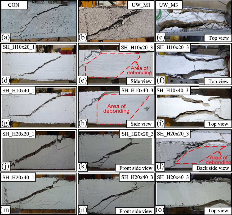
Failure Modes
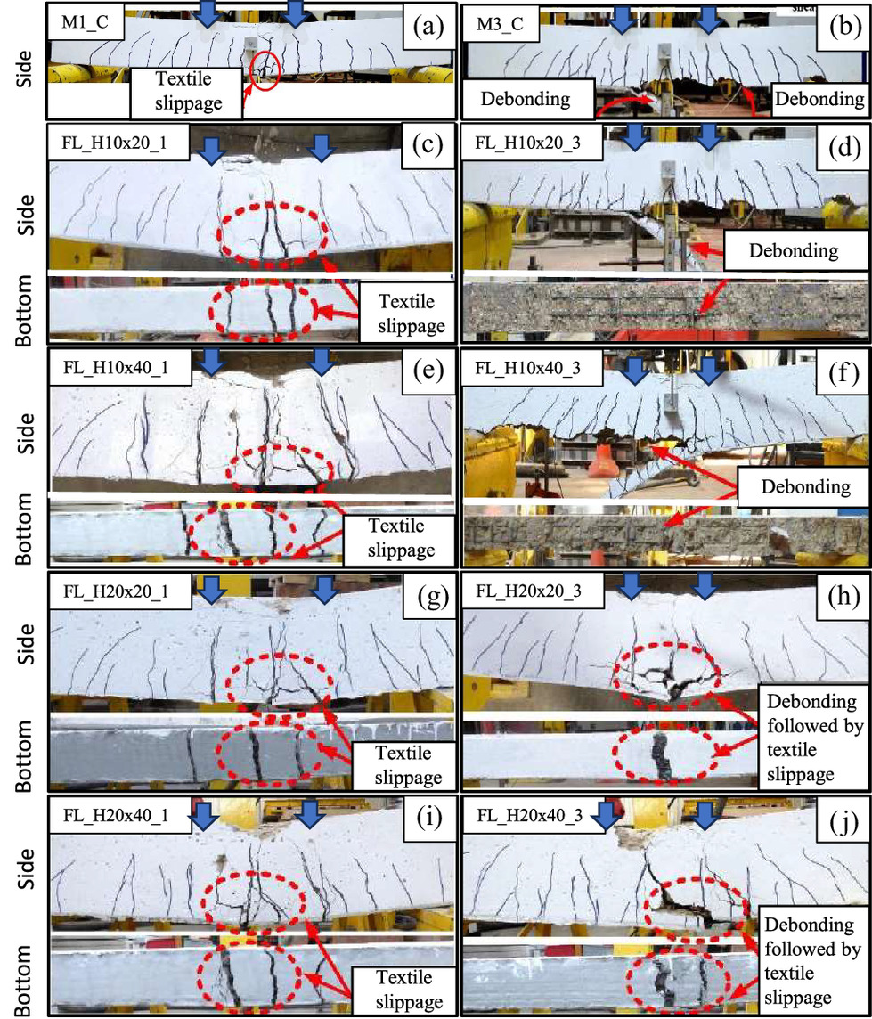
All beams failed according to their design, for instance, in a flexural manner. No shear damage was observed in any of the beams apart from some minor inclined cracks near the supports during the final loading stages. The control specimen (CON) failure mode was typical for under-reinforced concrete beams, which included yielding in the main tensile steel reinforcement followed by crushing of the concrete in the compression zone. The failure modes for the retrofitted RC members are shown in Fig. 8. The beams with one TRM layer failed due to localized damage due to the fibers’ slippage within the mortar in the cracked sections, as shown in Fig. 8. In these beams, the slippage in the fibers was gradual (telescopic failure). It progressed with the development of flexural cracks, which resulted in a pseudo-ductile structural response. In the beams with three TRM layers, the failure shifted from the textile–mortar interface to the concrete substrate. The typical observed failure was the debonding of the TRM layers from the beam together with the adjacent concrete cover, as shown in Fig. 8, which indicated that the textile reinforcement was utilized to a higher degree. Of note, the beams that were strengthened with three layers of textiles with larger grid spacing (FL_20 × 20_3 and FL_20 × 40_3) showed a mixed type of failure that involved fiber slippage (slippage of fibers within the mortar) and the debonding mechanisms (debonding from the concrete substrate where part of the concrete cover remained attached to the TRM jacket), which indicated that textiles geometry could affect the failure mode.
Load–Deflection Response
The load–deflection curves for all tested beams are shown in Fig. 9. Each graph contains the control specimens and the results for two beams with hybrid textiles that had two different secondary roving configurations. Therefore, the effect of the secondary reinforcement on the overall response can be seen. The response of the beams was typical for TRM-strengthened RC beams. Three visible stages were distinguished: (1) initial elastic response of uncracked beam; (2) response of cracked section; and (3) postyielding response up to failure. These stages are represented by the ascending curves with a decreasing slope [Fig. 9(a)].
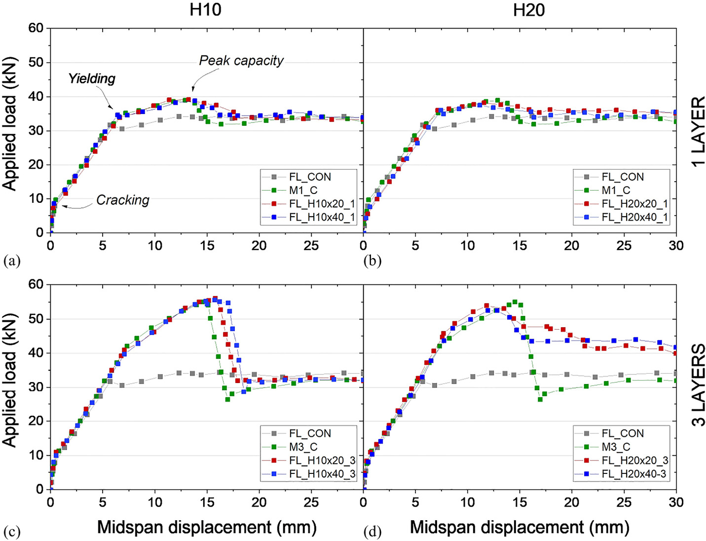
The addition of TRM could alter the onset of these stages. Therefore, slightly higher load values could be attained at cracking, yielding, and failure compared with CON, and this increase was more pronounced for the beams with an increased number of TRM layers (Table 5). The contribution of the TRM to the overall flexural behavior is observed after yielding in the main steel reinforcement. The lowest and highest load increase was recorded for FL_H20 × 40_1 and FL_H10 × 20_3, which developed maximum loads that were 9.5% and 62.4% higher than the control beam, respectively. The load increase recorded for all TRM-strengthened beams was from 9.5% to 13.9% and 56.6% to 62.4% for one and three layers, respectively.
The different textile geometries that were used did not significantly affect the stiffness or the deflection capacities of the repaired beams. Similar load paths were observed for the members with a standard 10 × 10 mm carbon mesh and hybrid carbon–glass mesh until the ultimate load was reached. This confirmed that the secondary transversal textile rovings did not contribute to the flexural strength of the beams, and a similar response could be achieved when weaker and cheaper fibers were used. However, the size of the grid spacing might affect the postpeak behavior slightly. This was demonstrated by comparing M3_C, FL_H20 × 20_3, and FL_H20 × 40_3 [Fig. 9(d)]. More discussion on the test results is presented in the “Discussion and Recommendations for Textile Optimization” section.
SH_Series Beams
The key results for the beams that were designed to fail in shear are listed in Table 6. The experimental data reported the peak load (Pmax), corresponding shear load at the test span (Vmax), and maximum deflection under the loading point at the peak load (δmax). The contribution of the TRM shear reinforcement for each beam was calculated as the difference between the shear capacity of the retrofitted beams and the control beam. Similar to the FL_Series beams, the efficiency of the strengthening was determined as the relative increase in the shear load capacity (ΔVmax) with respect to the control beam.
| Specimen | Pmax (kN) | Vmax (kN) | δmax (mm) | Vf = ΔVmax (kN) | ΔVmax/Vmax,con (%) | Failure mode |
|---|---|---|---|---|---|---|
| CONa | 51.8 | 29.7 | 2.3 | — | — | DTC |
| UW_M1a | 78.2 | 44.8 | 3.1 | 15.1 | 50.8 | S |
| UW_M3a | 131.1 | 75.1 | 5.5 | 45.4 | 152.9 | D |
| SH_H10 × 20_1 | 76.4 | 43.8 | 3.2 | 14.1 | 47.5 | S |
| SH_H10 × 20_3 | 132.9 | 76.1 | 5.3 | 46.4 | 156.2 | D |
| SH_H10 × 40_1 | 74.1 | 42.5 | 2.9 | 12.8 | 43.1 | S |
| SH_H10 × 40_3 | 137.4 | 78.7 | 5.5 | 49 | 165.0 | D |
| SH_H20 × 20_1 | 69.1 | 39.6 | 2.6 | 9.9 | 33.3 | S |
| SH_H20 × 20_3 | 123.1 | 70.5 | 4.4 | 40.8 | 137.4 | DS |
| SH_H20 × 40_1 | 72.0 | 41.2 | 3.5 | 11.5 | 38.7 | S |
| SH_H20 × 40_3 | 118.4 | 67.8 | 5.1 | 38.1 | 128.3 | DS |
Note: DTC = diagonal tensile crack; S = slippage and partial rupture of the fibers through the mortar; D = TRM debonding from concrete substrate; and DS = debonding of TRM from concrete substrate, followed by slippage in the fibers.
a
Specimen presented in Tetta et al. (2015).
Failure Modes
The damage patterns for all beams are shown in Fig. 10. All SH_Series beams failed in shear as expected from their design. The reference CON failed after a typical diagonal shear crack across the test shear span [Fig. 10(a)] developed. Due to the dowel action that was provided by the 16 mm rebars, the beam did not fail abruptly but exhibited a more ductile postpeak response. The members with additional TRM jackets showed better response, which confirmed the effectiveness of the U-shaped jacketing. The failure of the beams with one TRM layer was more gradual compared with the beams with three layers. This was associated with two local phenomena that occurred in the TRM jacket: (1) slippage in the vertical fiber rovings through the mortar; and (2) partial rupture of the fibers that crossed the shear crack. This failure was seen in all members that were retrofitted with one TRM layer [Fig. 10(b, d, g, j, and m)]. The failure of the beams that received three TRM layers was abrupt, with debonding in a large part of the side concrete cover [Fig. 10(c, e, h, l, and o)]. However, Specimens F20 × 20_3 and F20 × 40_3, which had larger textile grids, exhibited a mixed type of failure. The TRM jacket was partially debonded on one side [Figs. 10(l and o)], and the damage to the jacket due to the slippage and partial rupture of the fibers was observed on the other side of the beam [Fig. 10(k and n)]. The asymmetric behavior could be attributed to imperfections that were imposed during the application of the strengthening. In summary, the experimental observations confirmed that the hybrid configuration of carbon and glass rovings produced similar shear cracking patterns as the standard 10 × 10 mm carbon grids when one TRM was used. When three TRM layers were used, only the H10 specimens exhibited similar failure modes with the reference 10 × 10 carbon grids and the H20 specimens produced mixed types of failure.
Load–Deflection Response
The load–deflection curves for all beams designed to fail in shear are shown in Fig. 11; the graphs are arranged in the same manner as for the FL_Series. The load ascending was near linear until the development of the main shear crack in the test shear span, which initiated the failure. All specimens showed a similar load path except for SH_H20 × 20_3, which showed slightly stiffer behavior. This could be attributed to the materials’ natural variability, which led to a steeper shear crack on the opposite side of the beam [Fig. 10(l)] and triggered a slightly stiffer response. In addition, the U-shaped TRM jacketing allowed the maximum deflection at the peak load to increase (Fig. 11 and Table 6).
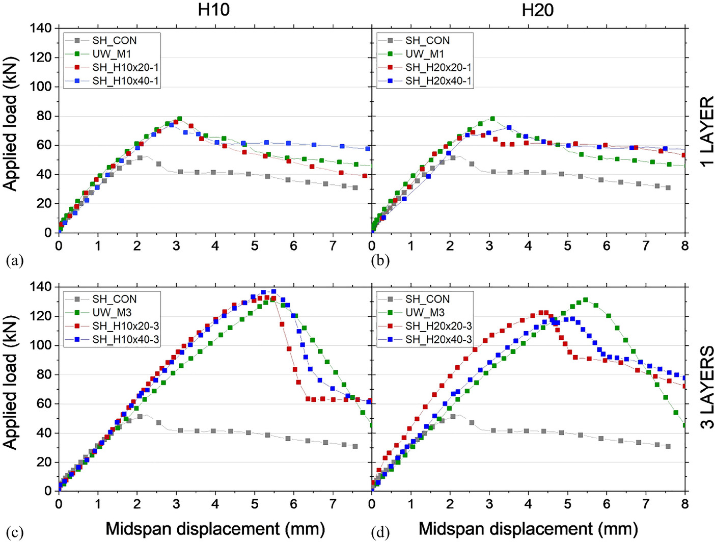
Even one layer of U-shaped TRM jacketing could provide a reasonable strength increase of up to approximately 50% compared with the control beam CON. The biggest gain in shear load capacity (up to 165%) was achieved when three layers of a hybrid 10 × 40 mm grid were used. The gain was slightly less for the standard 10 × 10 mm carbon mesh (approximately 153%). The results indicated that similar capacities and deformation levels could be observed regardless of the type and spacing of the secondary textile rovings. Therefore, the rovings that ran parallel to the beam’s axis (weft direction) had a negligible contribution to shear. Almost the entire shear contribution relied on warp textile rovings that were perpendicular to the beam’s axis, as shown in the comparisons in Fig. 11(a–d). However, maintaining the amount of textile fibers in the main resisting direction (vertical) but at an increased spacing restrained the shear crack from opening in the beams with three TRM layers. This led to a slightly lower maximum load capacity, as shown by SH_H20 × 20_3 and SH_H20 × 20_3 in Fig. 11(d). A more detailed discussion is provided in the “Discussion and Recommendations for Textile Optimization” section.
Discussion and Recommendations for Textile Optimization
Based on the test results that were presented in the previous sections, a discussion on the role of the investigated parameters is presented in this section. The discussion is carried out in terms of the effect of each parameter on several aspects of the structural behavior of the retrofitted beams, with a focus on the increase in the ultimate flexural and shear capacity. First, the effect of a number of TRM layers is discussed, followed by the effect of the different textile geometries. Finally, a set of preliminary recommendations on the optimization of textiles is provided.
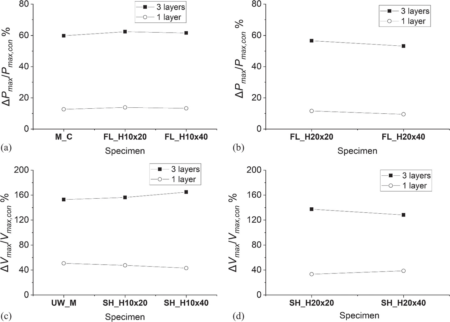
Effect of Number of Layers
The number of TRM strengthening layers was examined for the different textiles that were used for flexural and shear strengthening. Fig. 12(a and b) show the capacity increase (with respect to the control specimens) for the specimens that were strengthened in flexure and shear, respectively, grouped by the number of TRM layers. Fig. 12(c) shows the effect of the number of layers on the ultimate capacity increase for each different textile, grouped by the type of test (flexure or shear). For example, the 4.7 effectiveness ratio for the CH textile in flexure tests [Fig. 12(c)] is the ratio of ΔPmax between specimens M3_C and M1_C; for instance, 20.7 to 4.4 kN (Table 5). Therefore, for a directly proportional effect of the number of layers, the effectiveness ratio between three layers and one layer should be three.
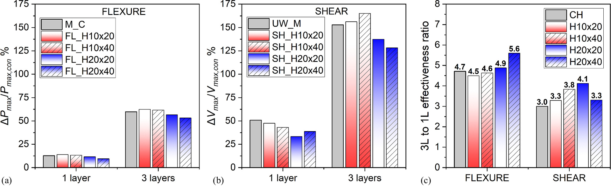
Therefore, for the flexural and shear tests, the strengthening effectiveness was not directly proportional to the number of layers. Specifically, when textiles without coatings (dry fibers) were used, the effectiveness of a one-layer TRM system was very limited. This was because of slippage between the fiber rovings and the mortar (localized failure mode). However, when the number of textile layers was tripled, the failure mechanism changed to debonding from the concrete substrate. The change in the failure mechanism resulted in superior performance and, therefore, a nonproportional increase in the capacity (more than three times). This phenomenon, which was attributed to the improved mechanical interlock that was achieved with more than two layers of textile reinforcement, has been observed in previous studies conducted by the authors (Tetta et al. 2015; Raoof et al. 2017). Therefore, the hybrid textile layouts investigated in this paper did not have any particular influence on the utilization of the fibers when three layers were applied and could successfully reproduce the behavior of conventional textiles.
Effect of Textile Geometry
Previous studies by the authors (Tetta et al. 2018a, b) evidenced that textile geometry altered the bond at the textile–mortar interface, which affected the overall performance of TRM strengthening. In an attempt to explore this aspect further, several mesh configurations were designed to investigate how the spacing of the fibers in the warp and weft direction could change the contribution of the TRM to the flexural and shear capacity of the RC beams. Fig. 13 shows the mesh pattern and textile geometry of all four textiles used in this paper. Of note, the contributions of the warp and weft fibers are discussed separately for the given roving spacing in the following sections.
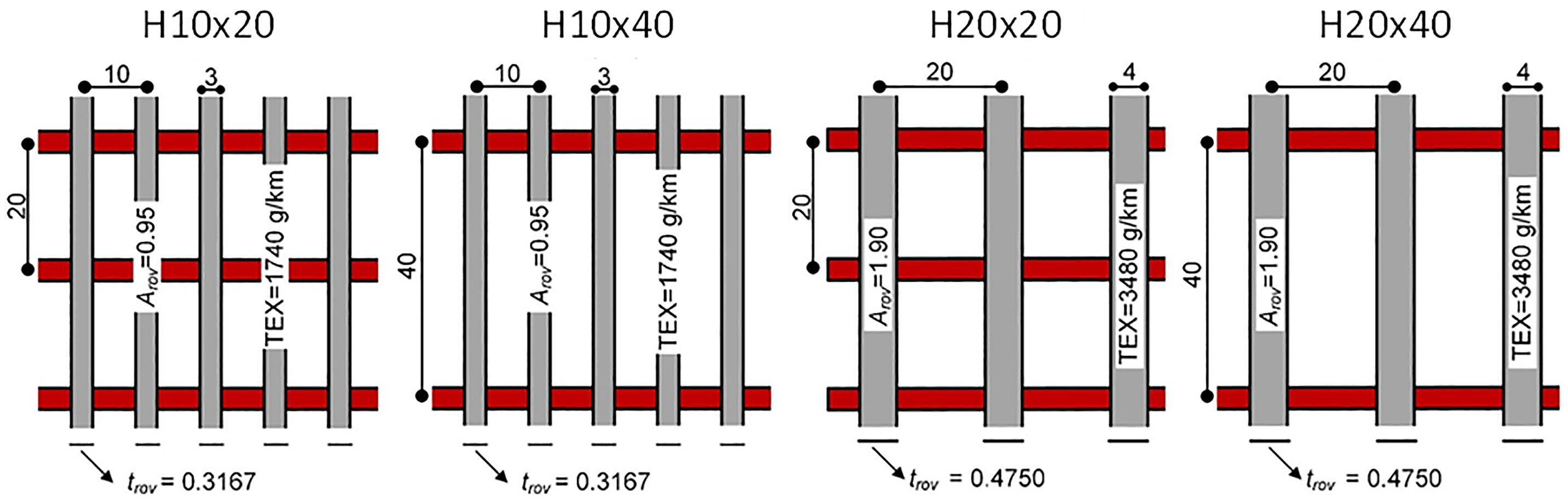
Spacing of Carbon Fiber Rovings in the Main (Warp) Direction
The main (warp) direction of the hybrid textiles that were used in this paper were composed of carbon fiber rovings, which were uniformly distributed in Groups H10 and H20, which had spacings between the carbon fiber rovings of 10 and 20 mm, respectively. The total area of fibers in the main direction of both textile groups was held constant by simply adjusting the area of the fibers in each roving. As shown in Fig. 3, the rovings in the H20 textiles had double the amount of fibers compared with the H10 textiles; therefore, all the textiles had the same equivalent thickness in the main direction of loading.
Fig. 14 shows the drop in the TRM strengthening effectiveness that was due to the configuration of the warp rovings. Without any exceptions, the strengthening effectiveness dropped when the warp spacing increased from 10 to 20 mm. Because the rovings in the H20 textiles had double the amount of fibers than the H10 textiles, their reduced effectiveness could be associated with the degree of the fibers’ impregnation with cement paste. The larger area of the fiber rovings in the H20 textiles resulted in poor impregnation of their core fibers compared with the H10 textiles.
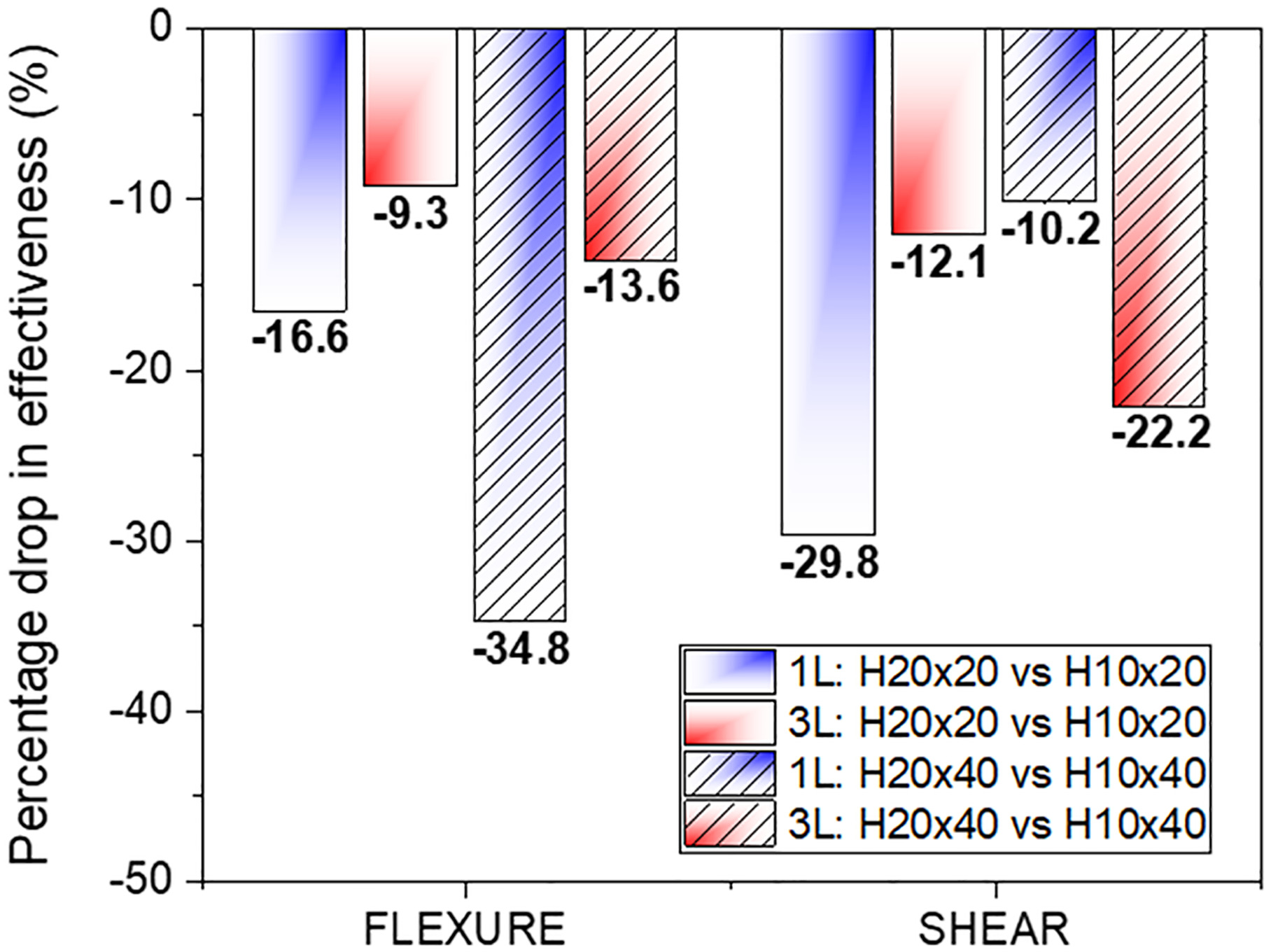
As shown in Fig. 14, the drop in the effectiveness between the H20 and H10 textiles was less pronounced in specimens with three TRM layers, which suggested that spacing of the main rovings became less important when more than one TRM layer was applied (Fig. 14). The only exception was noted in the shear tests for the ×40 textiles (40 mm spacing of the secondary rovings). In this case, the effectiveness drop was more pronounced in specimens with three TRM layers. The authors believe that the inconsistency in the results might be attributed to the potential loss of the structural integrity of the textile when the mesh size reached 20 × 40 mm, in particular, when the textiles were not coated. Therefore, the spacing of the uncoated fiber rovings might have limitations. Although this needs further experimental investigation, some preliminary recommendations have been proposed by the authors in the final sections of this paper.
Spacing of the Glass Fiber Rovings in the Secondary (Weft) Direction
The secondary (weft) direction of the hybrid textiles that were used in this paper was composed of glass fiber rovings that were uniformly distributed in Groups H_…_20 and H_…_40, which had spacings between the glass fiber rovings of 20 and 40 mm, respectively. To isolate the effect of the secondary fiber rovings on the strengthening effectiveness, the specimens were compared based on the same number of layers and spacings of the carbon fiber rovings in the main direction. This effect is shown in Fig. 15.
Conclusions on how the spacing in the weft direction could affect the strengthening efficiency could not be identified; however, a general conclusion was drawn. Increasing the spacing of the secondary fiber rovings (which could lead to substantial material and cost savings) had a negligible effect on the TRM performance for flexure and shear strengthening. This was the most interesting conclusion of this paper. In addition, if it can be verified by future research studies, it could open a new scope for a more optimized and cost-effective design of TRM for RC structures.
Cost-wise, double spacing in the secondary direction reduced the cost of the raw materials in this direction by half. Using hybrid textiles, the cost could be reduced even more drastically by utilizing glass (or even cheaper polypropylene) fibers instead of carbon fibers in the secondary direction. The latter led to significant savings on raw materials. Table 7 presents indicative costs of the fiber rovings in the secondary (weft) direction of the textiles that were used in this paper ($/m2). The use of weaker and cheaper glass fibers in the weft direction could lead to a dramatic reduction in the cost of the raw materials in this direction. However, these cost savings related to the manufacturers and the prices for the end-users would have to include the margins that are imposed by the textile suppliers.
| Description | CH10 × 10 | H10 × 20 and H20 × 20 | H10 × 40 and H20 × 40 |
|---|---|---|---|
| Material in weft direction | Carbon fiber rovings | AR glass fiber rovings | AR glass fiber rovings |
| Weight of textile in weft direction | 174 g/m2 | 40 g/m2 | 20 g/m2 |
| Indicative cost of raw materials (per kg) | $30 | $1 | $1 |
| Estimated cost of fiber rovings in weft direction (per m2) | $5 | $0.04 | $0.02 |
Some lessons could be learned on the weft fibers’ contribution to the interlocking mechanism, which might play a key role in the effectiveness of TRM systems for shear strengthening in RC beams and columns. The results presented in this paper indicated that the interlocking mechanism was not affected by the mesh size of uncoated textiles and did not govern the behavior of uncoated textiles. The behavior of uncoated textiles appears to be governed by the interfacial bond between the fiber rovings and the mortar. However, this conclusion should be treated with caution until it has been experimentally verified. This conclusion might not be valid for certain textile–mortar interfacial bond conditions for coated textiles.
Recommendations
Based on the previous discussion, a short list of recommendations is suggested for a more optimized design of textiles that are used for flexural and shear strengthening of RC beams.
1.
As in standard textile reinforcement, providing more than one TRM layer should be preferred in hybrid textiles to avoid local slippage mechanisms and enable better fiber utilization.
2.
In the main (warp) direction of textiles, fiber rovings with a small amount of fibers at short spacings (e.g., 8–10 mm) should be preferred over the fiber rovings with a higher amount of fibers at larger spacings (e.g., 20 mm or above).
3.
In the secondary (weft) direction of textiles, the glass fiber rovings with low TEX values (e.g., 600 g/km or higher) could be used instead of carbon fiber rovings, preferably spaced at 20 mm due to the loss of structural integrity when shifting to larger spacings. For larger spacings, coating of the textiles would be necessary to guarantee the structural integrity of the textile during application. However, this needs further investigation.
4.
For the performance of hybrid textiles compared with conventional textiles; until more data becomes available, designers could assume that carbon–glass hybrid textiles have a similar performance to conventional carbon–carbon textiles. For design purposes, a safety factor could be introduced (e.g., safety factor ≥1.2) to consider limitations in the effectiveness of the hybrid textiles.
Conclusions
This paper aimed to experimentally investigate the efficiency of hybrid carbon–glass textile reinforcement in the flexural and shear strengthening of RC members with TRM compared with conventional nonhybrid textiles made from carbon fibers. In addition, the effect of the textile geometry on the strengthening efficiency was experimentally studied. In total, 22 half-scale rectangular section RC beams were tested as simply supported. The first 11 beams were designed to fail in bending (FL_Series), and the remaining 11 were designed to fail in shear (SH_Series). In each test series, one beam was tested without strengthening and served as a reference specimen, and 10 were tested after being strengthened with different strengthening configurations. Various TRM systems were investigated: (1) a nonhybrid carbon fiber textile with 50%–50% distribution of fibers in two orthogonal directions; and (2) four carbon or glass fiber hybrid textiles with variations in the spacing of either the main (warp) carbon fiber rovings or the secondary (weft) glass fiber rovings. The main investigated parameters in the flexure and shear test series included: (1) the number of TRM layers; (2) the roving spacing in the warp directions; and (3) the roving spacing in the weft direction. The main conclusions of this paper are summarized as follows.
1.
All carbon–glass hybrid textiles were effective in substantially enhancing the flexural or shear capacity of RC members. The flexural capacity enhancement in RC beams varied between 9% and 14% when one layer was applied and between 53% and 62% when three layers were applied. The shear capacity enhancement was in the range of 33%–47% for one TRM layer and 128%–165% for three TRM layers.
2.
The flexural and shear capacity enhancement was not proportional to the number of layers that were applied. The use of three textile layers resulted in a nonproportional increase in the ultimate capacity of the beams (more than three times) and altered the failure mode. This behavior was common for the hybrid and nonhybrid textiles.
3.
Doubling the spacing of the main (warp) carbon fiber rovings and, therefore, lumping the same amount of fibers in fewer rovings resulted in a smaller contribution from the TRM to the overall flexural and shear capacity of the RC beams. This negative effect was associated with poor impregnation of the inner fibers and, therefore, reduced the bond between the textile and the mortar.
4.
There was no substantial negative impact of the secondary (weft) fiber roving spacing on the flexural and shear enhancement in the RC beams. Fiber rovings that were composed of alkali-resistant (AR) glass fibers with 600 g/km TEX spaced at 20 or 40 mm resulted in an overall similar performance of the TRM system with minor exceptions.
5.
By analyzing the load–deflection response of the tested elements and the failure patterns, it was concluded that hybrid textiles could perform in the cementitious matrix as well as the conventional ones. Therefore, they could be a viable and cost-efficient solution when strengthening RC linear elements.
The reported experimental data provides strong evidence that hybrid carbon–glass fiber textiles could replicate standard textile mesh systems with homogeneous carbon fibers. This might lead to considerable savings on materials and costs for TRM retrofitting applications in RC structures. However, based on the limited data that is currently available, the conclusions of this paper should be treated with caution, because they might only apply to the selected materials that were used (e.g., uncoated fibers). Future research should be directed toward further investigation of other types of hybrid textiles (e.g., coated textiles, carbon–basalt, or carbon–polypropylene textiles) and their effectiveness in other applications, such as TRM jackets in plastic hinge formations in RC columns or even the use of hybrid textiles for TRM strengthening of masonry.
Data Availability Statement
All data, models, or codes that support the findings of this study are available from the corresponding author upon reasonable request.
Acknowledgments
The experimental work described in the paper had been conducted at the University of Nottingham. The data postprocessing work was supported by the JRC Project iRESIST+ innovative seismic and energy retrofitting of the existing building stock. The first and second authors acknowledge funding through the H2020 Marie Curie Individual Fellowship program THORAX: Next Generation of Advanced Materials for Sustainable Retrofitting of Structures (Grant Agreement 892406).
References
ACI (American Concrete Institute). 2013. Guide to design and construction of externally bonded fabric-reinforced cementitious matrix (FRCM) systems for repair and strengthening concrete and masonry structures. ACI 549.4R-13. Farmington Hills, MI: ACI.
Akbari Hadad, H., A. Nanni, U. A. Ebead, and A. El Refai. 2018. “Static and fatigue performance of FRCM-strengthened concrete beams.” J. Compos. Constr. 22 (5): 04018033. https://doi.org/10.1061/(ASCE)CC.1943-5614.0000868.
Al-Salloum, Y. A., N. A. Siddiqui, H. M. Elsanadedy, A. A. Abadel, and M. A. Aqel. 2011. “Textile-reinforced mortar versus FRP as strengthening material for seismically deficient RC beam-column joints.” J. Compos. Constr. 15 (6): 920–933. https://doi.org/10.1061/(ASCE)CC.1943-5614.0000222.
Arce, A., A. Komkova, J. Van De Sande, C. G. Papanicolaou, and T. C. Triantafillou. 2022. “Optimal design of Ferronickel slag alkali-activated material for high thermal load applications developed by design of experiment.” Materials 15 (13): 4379. https://doi.org/10.3390/ma15134379.
Awani, O., T. El-Maaddawy, and A. El Refai. 2017. “Fabric-reinforced cementitious matrix: A promising strengthening technique for concrete structures.” Constr. Build. Mater. 132: 94–111. https://doi.org/10.1016/j.conbuildmat.2016.11.125.
Baek, E., D. A. Pohoryles, S. Kallioras, D. A. Bournas, H. Choi, and T. Kim. 2022. “Innovative seismic and energy retrofitting of wall envelopes using prefabricated textile-reinforced concrete panels with an embedded capillary tube system.” Eng. Struct. 265: 114453. https://doi.org/10.1016/j.engstruct.2022.114453.
Bournas, D. 2016. “Strengthening of existing structures: Selected case studies.” In Textile fibre composites in civil engineering, edited by T. Triantafillou, 389–411. Cambridge, UK: Woodhead Publishing.
Bournas, D. A. 2018. “Concurrent seismic and energy retrofitting of RC and masonry building envelopes using inorganic textile-based composites combined with insulation materials: A new concept.” Composites, Part B 148: 166–179. https://doi.org/10.1016/j.compositesb.2018.04.002.
Bournas, D. A., P. V. Lontou, C. G. Papanicolaou, and T. C. Triantafillou. 2007. “Textile-reinforced mortar versus fibre-reinforced polymer confinement in reinforced concrete columns.” ACI Struct. J. 104 (6): 740–748.
Brückner, A., R. Ortlepp, and M. Curbach. 2006. “Textile reinforced concrete for strengthening in bending and shear.” Mater. Struct. 39 (8): 741–748. https://doi.org/10.1617/s11527-005-9027-2.
CEN (European Committee for Standardization). 2019. Methods of test for mortar for masonry – Part 11: Determination of flexural and compressive strength of hardened mortar. EN-1015. Brussels, Belgium: CEN.
Cerniauskas, G., Z. Tetta, D. A. Bournas, and L. A. Bisby. 2020. “Concrete confinement with TRM versus FRP jackets at elevated temperatures.” Mater. Struct. 53 (3): 1–14. https://doi.org/10.1617/s11527-020-01492-x.
Cholostiakow, S., L. N. Koutas, and C. G. Papakonstantinou. 2023. “Geopolymer versus cement-based textile-reinforced mortar: Diagonal compression tests on masonry walls representative of infills in RC frames.” Constr. Build. Mater. 373: 130836. https://doi.org/10.1016/j.conbuildmat.2023.130836.
Dalalbashi, A., B. Ghiassi, and D. V. Oliveira. 2019. “Textile-to-mortar bond behaviour in lime-based textile reinforced mortars.” Constr. Build. Mater. 227: 116682. https://doi.org/10.1016/j.conbuildmat.2019.116682.
D’Ambrisi, A., and F. Focacci. 2011. “Flexural strengthening of RC beams with cement-based composites.” J. Compos. Constr. 15 (5): 707–720. https://doi.org/10.1061/(ASCE)CC.1943-5614.0000218.
D’Antino, T., and C. C. Papanicolaou. 2018. “Comparison between different tensile test set-ups for the mechanical characterization of inorganic-matrix composites.” Constr. Build. Mater. 171: 140–151. https://doi.org/10.1016/j.conbuildmat.2018.03.041.
Ebead, U., K. C. Shrestha, M. S. Afzal, A. El Refai, and A. Nanni. 2017. “Effectiveness of fabric-reinforced cementitious matrix in strengthening reinforced concrete beams.” J. Compos. Constr. 21 (2): 04016084. https://doi.org/10.1061/(ASCE)CC.1943-5614.0000741.
Elghazy, M., A. El Refai, U. Ebead, and A. Nanni. 2018a. “Post-repair flexural performance of corrosion-damaged beams rehabilitated with fabric-reinforced cementitious matrix (FRCM).” Constr. Build. Mater. 166: 732–744. https://doi.org/10.1016/j.conbuildmat.2018.01.128.
Elghazy, M., A. El Refai, U. Ebead, and A. Nanni. 2018b. “Fatigue and monotonic behaviors of corrosion-damaged reinforced concrete beams strengthened with FRCM composites.” J. Compos. Constr. 22 (5): 04018040. https://doi.org/10.1061/(ASCE)CC.1943-5614.0000875.
Elsanadedy, H. M., T. H. Almusallam, S. H. Alsayed, and Y. A. Al-Salloum. 2013. “Flexural strengthening of RC beams using textile reinforced mortar—Experimental and numerical study.” Compos. Struct. 97: 40–55. https://doi.org/10.1016/j.compstruct.2012.09.053.
Ferrara, G., C. Caggegi, E. Martinelli, and A. Gabor. 2020. “Shear capacity of masonry walls externally strengthened using Flax-TRM composite systems: Experimental tests and comparative assessment.” Constr. Build. Mater. 261: 120490. https://doi.org/10.1016/j.conbuildmat.2020.120490.
fib (Fédération Internationale du Béton). 2022. Guide for strengthening of concrete structures. fib bulletin no. 103. Lausanne, Switzerland: fib.
Filippou, C., A. Furtado, M. T. De Risi, N. Kyriakides, and C. Z. Chrysostomou. 2022. “Behaviour of masonry-infilled RC frames strengthened using textile reinforced mortar: An experimental and numerical studies overview.” J. Earthquake Eng. 26: 7743–7767. https://doi.org/10.1080/13632469.2021.1988763.
Focacci, F., T. D’Antino, and C. Carloni. 2022. “Tensile testing of FRCM coupons for material characterization: Discussion of critical aspects.” J. Compos. Constr. 26 (4): 04022039. https://doi.org/10.1061/(ASCE)CC.1943-5614.0001223.
Furtado, A., A. Arêde, and H. Rodrigues. 2022. “The effect of a textile-reinforced mortar on the flexural response of energy-improved infill walls.” J. Compos. Constr. 26 (5): 04022047. https://doi.org/10.1061/(ASCE)CC.1943-5614.0001237.
Gkournelos, P. D., D. A. Bournas, and T. C. Triantafillou. 2019. “Combined seismic and energy upgrading of existing reinforced concrete buildings using TRM jacketing and thermal insulation.” Earthquakes Struct. 16: 625–639. https://doi.org/10.12989/eas.2019.16.5.625.
Gkournelos, P. D., L. D. Azdejković, and T. C. Triantafillou. 2022a. “Innovative and Eco-friendly solutions for the seismic retrofitting of natural stone masonry walls with textile reinforced mortar: In- and Out-of-plane behavior.” J. Compos. Constr. 26 (1): 04021061. https://doi.org/10.1061/(ASCE)CC.1943-5614.0001173.
Gkournelos, P. D., T. C. Triantafillou, and D. A. Bournas. 2021. “Seismic upgrading of existing reinforced concrete buildings: A state-of-the-art review.” Eng. Struct. 240: 112273. https://doi.org/10.1016/j.engstruct.2021.112273.
Gkournelos, P. D., T. C. Triantafillou, and D. A. Bournas. 2022b. “Seismic upgrading of existing masonry structures: A state-of-the-art review.” Soil Dyn. Earthquake Eng. 161: 107428. https://doi.org/10.1016/j.soildyn.2022.107428.
Hadad, H. A., B. Erickson, and A. Nanni. 2020. “Flexural analysis and design of FRCM-strengthened RC beams.” Constr. Build. Mater. 244: 118371. https://doi.org/10.1016/j.conbuildmat.2020.118371.
Kariou, F. A., S. P. Triantafyllou, D. A. Bournas, and L. N. Koutas. 2018. “Out-of-plane response of masonry walls strengthened using textile-mortar system.” Constr. Build. Mater. 165: 769–781. https://doi.org/10.1016/j.conbuildmat.2018.01.026.
Kouris, L. A. S., and T. C. Triantafillou. 2018. “State-of-the-art on strengthening of masonry structures with textile reinforced mortar (TRM).” Constr. Build. Mater. 188: 1221–1233. https://doi.org/10.1016/j.conbuildmat.2018.08.039.
Koutas, L., S. N. Bousias, and T. C. Triantafillou. 2014. “Seismic strengthening of masonry-infilled RC frames with TRM: Experimental study.” J. Compos. Constr. 19 (2): 04014048. https://doi.org/10.1061/(ASCE)CC.1943-5614.0000507.
Koutas, L. N., and D. A. Bournas. 2017. “Flexural strengthening of two-way RC slabs with textile-reinforced mortar: Experimental investigation and design equations.” J. Compos. Constr 21 (1): 04016065. https://doi.org/10.1061/(ASCE)CC.1943-5614.0000713.
Koutas, L. N., and D. A. Bournas. 2019. “Out-of-plane strengthening of masonry-infilled RC frames with textile-reinforced mortar jackets.” J. Compos. Constr. 23 (1): 04018079. https://doi.org/10.1061/(ASCE)CC.1943-5614.0000911.
Koutas, L. N., and C. G. Papakonstantinou. 2021. “Flexural strengthening of RC beams with textile-reinforced mortar composites focusing on the influence of the mortar type.” Eng. Struct. 246: 113060. https://doi.org/10.1016/j.engstruct.2021.113060.
Koutas, L. N., Z. Tetta, D. A. Bournas, and T. C. Triantafillou. 2019. “Strengthening of concrete structures with textile reinforced mortars: State-of-the-art review.” J. Compos. Constr. 23 (1): 03118001. https://doi.org/10.1061/(ASCE)CC.1943-5614.0000882.
Liu, D., H. Huang, J. Zuo, K. Duan, Y. Xue, and Y. Li. 2017. “Experimental and numerical study on short eccentric columns strengthened by textile-reinforced concrete under sustaining load.” J. Reinf. Plast. Compos. 36 (23): 1712–1726. https://doi.org/10.1177/0731684417725396.
Longo, F., A. Cascardi, P. Lassandro, and M. A. Aiello. 2020. “A new fabric reinforced geopolymer mortar (FRGM) with mechanical and energy benefits.” Fibers 8 (8): 49. https://doi.org/10.3390/fib8080049.
NRC (National Research Council). 2018. Istruzioni per la Progettazione, l'Esecuzione ed il Controllo di Interventi di Consolidamento Statico mediante l’utilizzo di Compositi Fibrorinforzati a matrice inorganica. CNR-DT 215/2018. Rome: NRC.
Pohoryles, D. A., and D. A. Bournas. 2020. “Seismic retrofit of infilled RC frames with textile reinforced mortars: State-of-the-art review and analytical modelling.” Composites, Part B 183: 107702. https://doi.org/10.1016/j.compositesb.2019.107702.
Pohoryles, D. A., C. Maduta, D. A. Bournas, and L. A. Kouris. 2020. “Energy performance of existing residential buildings in Europe: A novel approach combining energy with seismic retrofitting.” Energy Build. 223: 110024. https://doi.org/10.1016/j.enbuild.2020.110024.
Raoof, S. M., and D. A. Bournas. 2017. “TRM versus FRP in flexural strengthening of RC beams: Behaviour at high temperatures.” Constr. Build. Mater. 154: 424–437. https://doi.org/10.1016/j.conbuildmat.2017.07.195.
Raoof, S. M., L. N. Koutas, and D. A. Bournas. 2017. “Textile-reinforced mortar (TRM) versus fibre-reinforced polymers (FRP) in flexural strengthening of RC beams.” Constr. Build. Mater. 151: 279–291. https://doi.org/10.1016/j.conbuildmat.2017.05.023.
RILEM (Réunion Internationale des Laboratoires et Experts des Matériaux). 2016. Design procedures for the use of composites in strengthening of reinforced concrete structures. State-of-the-Art Report of the RILEM Technical Committee 234-DUC. Dordrecht, Netherlands: Springer.
Signorini, C., A. Sola, A. Nobili, and C. Siligardi. 2019. “Lime-cement textile reinforced mortar (TRM) with modified interphase.” J. Appl. Biomater. Funct. Mater. 17 (1): 228080001982782. https://doi.org/10.1177/2280800019827823.
Skyrianou, I., C. G. Papakonstantinou, and L. N. Koutas. 2022. “Advanced composites with alkali-activated matrices for strengthening of concrete structures: Review study.” Key Eng. Mater. 919: 65–71. https://doi.org/10.4028/p-sm2iot.
Sui, Z.-A., K. Dong, J. Jiang, S. Yang, and K. Hu. 2020. “Flexural behavior of fire-damaged prefabricated RC hollow slabs strengthened with CFRP versus TRM.” Materials 13 (11): 2556. https://doi.org/10.3390/ma13112556.
Tetta, Z. C., and D. A. Bournas. 2016. “TRM vs FRP jacketing in shear strengthening of concrete members subjected to high temperatures.” Composites, Part B 106: 190–205. https://doi.org/10.1016/j.compositesb.2016.09.026.
Tetta, Z. C., L. N. Koutas, and D. A. Bournas. 2015. “Textile-reinforced mortar (TRM) versus fiber-reinforced polymers (FRP) in shear strengthening of concrete beams.” Composites, Part B 77: 338–348. https://doi.org/10.1016/j.compositesb.2015.03.055.
Tetta, Z. C., L. N. Koutas, and D. A. Bournas. 2018a. “Shear strengthening of concrete members with TRM jackets: Effect of shear span-to-depth ratio, material and amount of external reinforcement.” Composites, Part B 137: 184–201. https://doi.org/10.1016/j.compositesb.2017.10.041.
Tetta, Z. C., T. C. Triantafillou, and D. A. Bournas. 2018b. “On the design of shear-strengthened RC members through the use of textile reinforced mortar overlays.” Composites, Part B 147: 178–196. https://doi.org/10.1016/j.compositesb.2018.04.008.
Triantafillou, T. C., K. Karlos, K. Kefalou, and E. Argyropoulou. 2017. “An innovative structural and energy retrofitting system for URM walls using textile reinforced mortars combined with thermal insulation: Mechanical and fire behavior.” Constr. Build. Mater. 133: 1–13. https://doi.org/10.1016/j.conbuildmat.2016.12.032.
Triantafillou, T. C., C. G. Papanicolaou, P. Zisimopoulos, and T. Laourdekis. 2006. “Concrete confinement with textile reinforced mortar (TRM) jackets.” ACI Struct. J. 103 (1): 28–37.
Trochoutsou, N., M. Di Benedetti, K. Pilakoutas, and M. Guadagnini. 2022. “In-plane cyclic performance of masonry walls retrofitted with flax textile–reinforced mortar overlays.” J. Compos. Constr. 26 (5): 04022049. https://doi.org/10.1061/(ASCE)CC.1943-5614.0001238.
Information & Authors
Information
Published In

Journal of Composites for Construction
Volume 28 • Issue 1 • February 2024
Copyright
This work is made available under the terms of the Creative Commons Attribution 4.0 International license, https://creativecommons.org/licenses/by/4.0/.
History
Received: Mar 30, 2023
Accepted: Aug 15, 2023
Published online: Nov 13, 2023
Published in print: Feb 1, 2024
Discussion open until: Apr 13, 2024
Authors
Metrics & Citations
Metrics
Citations
Download citation
If you have the appropriate software installed, you can download article citation data to the citation manager of your choice. Simply select your manager software from the list below and click Download.