Geometrically Exact Aeroelastic Stability Analysis of Composite Helicopter Rotor Blades in Hover by Updated VABS
Publication: Journal of Aerospace Engineering
Volume 37, Issue 2
Abstract
Accurate methods for geometrically exact aeroelastic stability analysis of composite helicopter rotor blades in hover have been proposed in this paper. The aeroelastic model is established by using the geometrically exact beam theory and the updated variational asymptotic beam sectional (VABS) analysis which can cover the effect of initial twist and curvatures and calculate accurately the structural properties of the blade cross section with arbitrary shape and material distribution. The Peters finite state airloads theory and Peters-He finite state dynamic wake model are adopted to calculate the three-dimensional unsteady airloads. To ensure the calculation accuracy of the geometrically exact aeroelastic stability of the blades, the time domain method based on the finite element spatial discretization, Newmark numerical integration and Newton-Raphson methods to calculate the aeroelastic responses of blades and the moving-block analysis to extract the regressive lag mode damping from the blade transient responses are established. The accuracy of the proposed methods is verified by experimental results. The investigation results indicate that the transverse shear deformation and initial curvatures of the blades have significant effects on the aeroelastic stability of the hingeless composite rotors in hover.
Practical Applications
The rotor blades of helicopter are the lift components of helicopter. Under the flight conditions of high speed, heavy load, and large maneuvering, the composite blades will produce large aeroelastic deformation and aeroelastic instability. Therefore, it is necessary to establish an accurate aeroelastic analysis method for composite blades of helicopters. In this paper, an accurate method for geometrically exact aeroelastic stability analysis of composite rotor blades of a helicopter in hover has been proposed with applications to sophisticatedly treat the anisotropy material properties, arbitrary cross-sectional shape and material distributions, and initial twist, and material distributions and initial twist and curvatures of composite rotor blades of a helicopter. The cross-sectional structural properties and large deflections of the blades under applied forces and moments can be calculated accurately and efficiently. The presented method may also be applied to the analysis of turbine blades, aircraft wings, and many other engineering structures with beam-like geometries and has potential applications in the structural and aeroelastic modeling of these beam-like structures.
Introduction
The geometrically exact nonlinear beam model developed by Hodges (2006) has gained considerable attention in the helicopter community because of its unique advantages. In the model, the three-dimensional (3D) geometrically nonlinear elastic analysis is transformed into one-dimensional (1D) geometrically exact beam analysis and two-dimensional (2D) variational asymptotic beam sectional (VABS) analysis using the variational asymptotic method. The arbitrary cross-sectional warping can be determined in the process of the transformation. The one-dimensional geometrically exact beam analysis does not impose any restrictions on displacements and rotations except for the small strain assumption, so it can be used to deal with the blades with large deflections. In addition, the geometrically exact equations of motion for the blade can be written in the mixed variational form, hence are very compact and can be solved with simple shape functions. The VABS analysis which was originally developed by Cesnik (1994) and Cesnik and Hodges (1997) can sophisticatedly treat the nonclassical effects such as the transverse shear deformation, cross-sectional warping, and elastic couplings caused by the anisotropy of composite materials and the arbitrary cross-sectional shape and material distribution of composite rotor blades.
The geometrically exact nonlinear beam model had been used to investigate the aeroelastic characteristics of composite rotor blades. Fulton and Hodges (1992, 1993a, b) investigated the aeroelastic stability of composite hingeless rotors in hover using the geometrically exact equations of motion for the blade in the mixed variational form (Hodges 1990). Shang and Hodges (1995), Shang (1995), Shang and Hodges (1996), and Shang et al. (1999) added Peters-He finite state dynamic wake model (Peters and He 1987; Peters et al. 1989; He 1989) to the aeroelastic model of Fulton and Hodges (1993a) and studied the aeroelastic response and aeroelastic stability of composite hingeless rotors in hover. Amoozgar and Shahverdi (2019) and Amoozgar et al. (2019a, b, c) investigated the aeroelastic stability of composite hingeless rotors in hover with the geometrically exact fully intrinsic equations of motion for the blade by Hodges (2006). All the aforementioned analyses used the linearized eigen-analysis method to obtain the aeroelastic stability of composite rotors. The linearized eigen-analysis method utilizes the linear system theory by the linearization of the aeroelastic equations, which is suitable for the aeroelastic stability analysis of linear or weakly nonlinear aeroelastic system and will weaken the nonlinear effects of aeroelastic systems and cause the inaccuracy of geometrically exact aeroelastic stability analysis of composite blades. What is more important, the direct analytical method or the original VABS (Cesnik 1994; Cesnik and Hodges 1997) was used to obtain the blade cross-sectional structural properties in the aforementioned studies. The direct analytical method adopts shell and plate theory by simplifying the realistic composite blade as a thin-walled or thick-walled beam, which is less accurate compared with the VABS analysis based on the finite element analysis. The original VABS assumes infinite shear stiffness and cannot take into account the effect of initial twist and curvatures which is necessary for blade geometrically exact modeling.
To improve the calculation accuracy and generality of blade cross-sectional structural properties, the original VABS (Cesnik 1994; Cesnik and Hodges 1997) was updated substantially by Ho et al. (2010a, b), Yu et al. (2012), and Hodges (2015). Popescu (1998) found that the generalized Timoshenko beam model established by Cesnik (1994) and Cesnik and Hodges (1997) was not asymptotically correct, and provided an approach to transform the generalized classical beam model into the asymptotically correct generalized Timoshenko beam model for prismatic beams. Yu (2002) further modified the generalized Timoshenko beam model established by Popescu (1998) by adding the initial twist and curvature into the model, using a more feasible transforming method and eliminating the limitation that the beam axis must be chosen at the cross-sectional centroid. Ho et al. (2010a, b) established a perturbation method considering all transformation terms of the strain energy including the higher order terms neglected by Yu (2002), insuring the accuracy of the analysis. The updated VABS contains all these aforementioned modifications. However, the geometrically exact nonlinear beam theory with the updated VABS has not been combined with aerodynamic models to analyze the composite blade aeroelastic stability. Composite rotor blades exhibit significant nonclassical effects such as transverse shear deformation, cross-sectional warping, and elastic couplings caused by the anisotropy of the composite materials. At present, the influence of cross-sectional warping and elastic couplings on the aeroelastic stability of composite rotor blades has been clear, but the influence of transverse shear deformation on the aeroelastic stability of composite rotor blades is still not clear (Shang et al. 2018, 2019; Jung et al. 2001, 2002; Hodges et al. 2007). In addition, the combined effect of initial curvature and elastic couplings on the aeroelastic stability of composite blades has not been investigated. Using the updated VABS for taking into account the effect of transverse shear deformation and initial curvature on the blade cross-sectional structural properties, these issues can be well addressed.
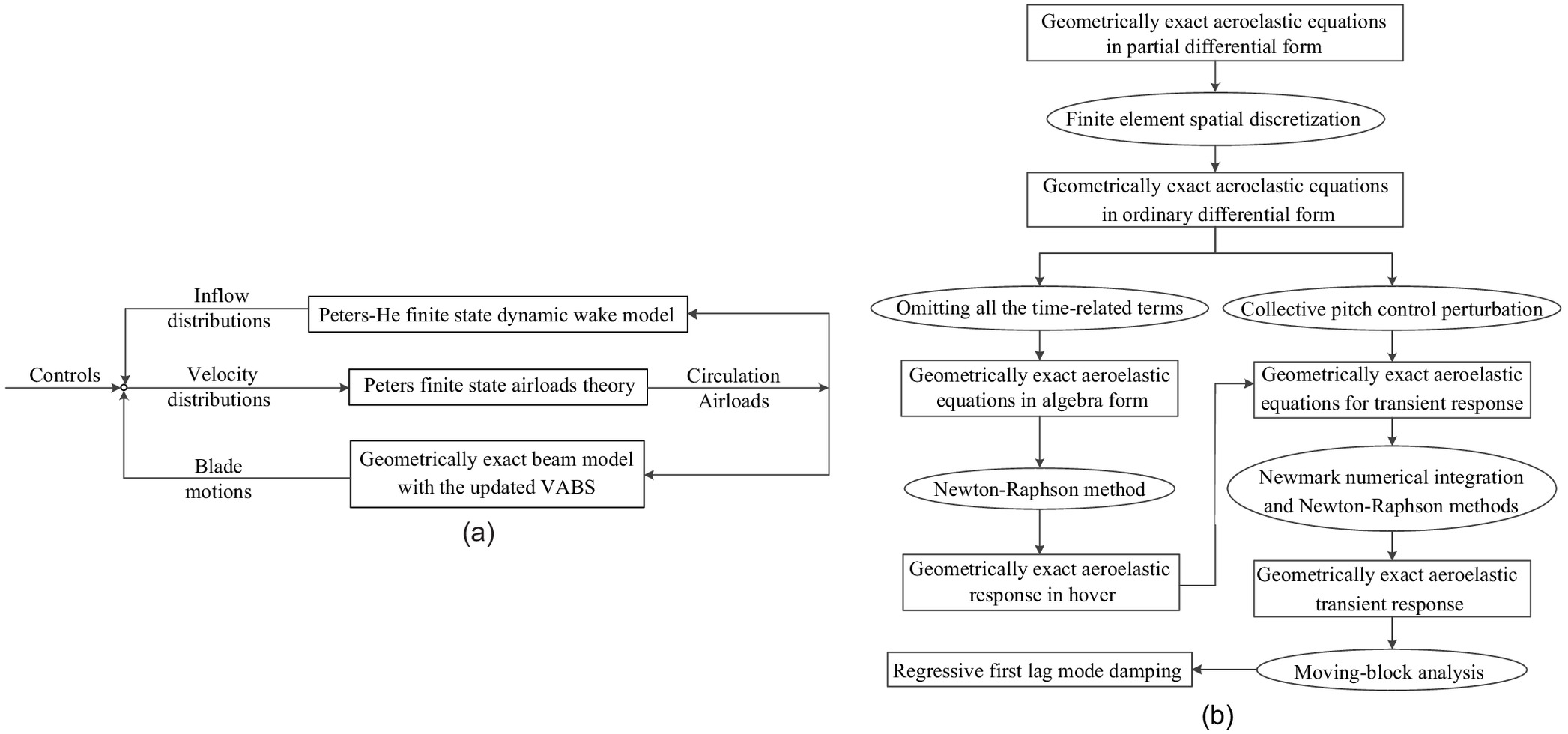
To add to the aforementioned literature, accurate methods for the geometrically exact aeroelastic stability analysis of composite helicopter rotor blades in hover have been presented in this paper. The geometrically exact beam model with the updated VABS (Ho et al. 2010a, b; Yu et al. 2012; Hodges 2015) and the 3D unsteady airloads based on the Peters finite state airloads theory (Peters et al. 2007) and Peters-He finite state dynamic wake model (Peters et al. 1989) in hover are used to establish the aeroelastic model of composite blades in hover. To avoid weakening the nonlinear effects, the transient response analysis method for analyzing the geometrically exact aeroelastic stability of composite blades is established. Moreover, by using the transient response analysis method, the presented aeroelastic modeling and solution methods can be expanded for forward flight with little extra effort. The finite element spatial discretization, Newmark numerical integration, and Newton-Raphson methods are adopted to solve the aeroelastic responses of composite blades in time domain. A moving-block analysis (Bousman and Winkler 1981) is used to analyze the transient aeroelastic responses under specific collective pitch control perturbations, which extracts the damping of the regressive lag mode for analysis of the aeroelastic stability of the blades. The calculation accuracy of the geometrically exact aeroelastic modeling and analytical methods is verified by the experimental results (Sharp 1986). With the updated ability of the VABS analysis, the effects of transverse shear deformation and initial curvatures of blades on the aeroelastic stability of composite hingeless rotor blades in hover are investigated. Flowcharts for the presented analysis method are shown in Fig. 1.
Geometrically Exact Aeroelastic Model of Composite Rotor Blades
Geometrically Exact Equations of Motion for Composite Rotor Blades
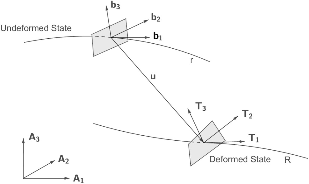
The geometrically exact nonlinear beam theory developed by Hodges (2006) is used to establish the equations of motion for composite rotor blades. The schematic of blade deformation from undeformed state to deformed state is shown in Fig. 2. The motion and deformation of the blade are described by three reference frames: the global reference frame A, the local undeformed reference frame b, and the local deformed reference frame T. The frame A is an absolute deformation frame and rotating with the rotor, and its origin is fixed at the center of the rotor disk. The undeformed blade reference line r is composed of the quarter-chord points of each section of the undeformed blade. For the frame b, its orthogonal unit vector is tangent to r; and vectors , are along the reference cross section of the undeformed blade. The rotation of the frame b relative to the frame A is caused by the blade collective pitch, initial twist and initial curvatures. The points along r undergo deformation, and their deformed locus is defined as the deformed blade reference line R. The displacement of a point on the reference line is represented as . For the frame T, its orthogonal unit vector is perpendicular to the reference cross section of the deformed blade; vectors and are along the reference cross section of the deformed blade; and is not necessarily tangent to R due to the transverse shear deformation effect. The rotation of the frame T relative to the frame b is caused by the blade deformation. The deformation of a point in the deformed blade relative to its corresponding frame T is caused by the warping of the blade cross section. The selection of the aforementioned reference frames can exactly represent the displacement of the blade reference line and the rotation of the blade reference cross section, that is, geometrically exact.
Based on the geometrically exact nonlinear beam theory by Hodges (2006), the geometrically exact equations of motion in the mixed variational form for the composite rotor blades can be expressed in the frame A aswhere
(1)
(2)
(3)
In Eqs. (1)–(3), = virtual displacement vector; = virtual rotation vector; and = vectors of the cross-sectional stress and moment resultant measures in the T basis, respectively; and = vectors of the cross-sectional linear and angular momentum measures in the T basis, respectively; = vector of the force strain measures corresponding to the extension, edgewise transverse shear and flapwise transverse shear, respectively; = vector of the moment strain measures corresponding to the torsion, flapwise bending and edgewise bending, respectively; = vector of the inertial velocity measures of an arbitrary point on the deformed blade reference line in the T basis; = vector of the inertial angular velocity measures of the frame T in the T basis; = vector of the displacement measures of an arbitrary point on the blade reference line in the A basis; = vector of the Rodrigues parameters; = vector of the inertial velocity measures of an arbitrary point on the undeformed blade reference line in the A basis; = vector of the inertial angular velocity measures of the frame A in the A basis; ; = identity matrix of order three; denotes the derivative with respect to which is the arclength along the undeformed blade reference line; denotes the derivative with respect to time ; represents an antisymmetric matrix whose components are where represents components of the permutation tensor; and , , , have the same form as . The single superscript T represents the transpose operator; = transformation matrix from frame b to frame A with as its transpose matrix; = finite rotation matrix; = vector of the distributed applied forces per unit length of the blade; and = vector of the distributed applied moments per unit length of the blade. The detailed derivation of Eq. (1), and the physical meanings and detailed expressions of the variables which are not explained here in Eqs. (1)–(3) can be found in Hodges (2006).
It is notable that the unknown variables in Eq. (1) include not only the blade displacement and rotation but also the blade cross-sectional stress resultant, moment resultant, linear momentum, and angular momentum. One advantage of this mixed variational form is that simple shape functions can be used for finite element spatial discretization, which simplifies the solving process of the equations of motion for the blade. Moreover, the blade root loads can be directly obtained as unknown variables by passing the need of the conventional force summation or modal summation calculation, which makes the hub loads calculation not only simpler but also more accurate compared with those conventional models. In addition, all the variational terms in Eq. (1) are represented in the global frame A. With this representation, when the blade is not straight, the finite element spatial discretization of Eq. (1) can be completed without complex coordinate transformations between adjacent elements. The matrix in Eq. (2) and the matrix in Eq. (3) are the cross-sectional stiffness and mass matrices of the blade, respectively. For composite blades with complex geometry and material distribution, is a fully coupled matrix. In this paper, is obtained from the updated VABS (Hodges 2015), which can accurately deal with the arbitrary cross-sectional geometry and material distribution of the blade, the effect of the blade initial twist and curvatures, and the nonclassical effects caused by anisotropic material properties, such as cross-sectional warping, transverse shear deformation, and elastic couplings. The matrix is also obtained from the updated VABS (Hodges 2015) by numerical integration over the reference cross section of the blade.
Three-Dimensional Unsteady Airloads on Blades
By the Peters finite state airloads theory (Peters et al. 2007), the aerodynamic forces and aerodynamic moments in the T basis can be expressed in terms of the aforementioned structural variables aswhere = air density; = blade chord; = lift curve slope of airfoil; = profile drag coefficient; and = components of the resultant air velocity along the vectors and , respectively, which depend on the blade motion and the induced velocity at the rotor disk; and = component of along the vector . In hover, = part of due to the blade motion. Hencewhere = rotor angular speed; = rotor radius; ; ; and = dimensionless induced velocity at the rotor disk, and is obtained from the Peters-He finite state dynamic wake model (Peters et al. 1989) by solving a set of inflow equations. For the presented model, the pressure integrals in the inflow equations are expressed in terms of the aforementioned structural variables aswhere and = harmonic number and polynomial number, respectively. The superscripts and denote the cosine part and sine part of the pressure integrals, respectively; = number of blades.; = dimensionless radial coordinate of blade; = radial expansion function; = azimuth of the th blade; and = sectional circulatory lift of the th blade and for the presented model
(4)
(5)
(6)
(7)
(8)
(9)
(10)
(11)
Solution Methodology of Geometrically Exact Aeroelastic Stability
The geometrically exact aeroelastic equations are composed of the geometrically exact equations of motion in the mixed variational form [i.e., Eq. (1)] and the inflow equations (Peters et al. 1989), and are a set of partial differential equations in the space and time domains. First, the finite element spatial discretization is performed on the aeroelastic equations. Eq. (1) is still in the weakest form, hence it can be spatially discretized into finite element form by using simple shape functions. The blade is divided into elements. Linear shape functions for , , , and , and constant shape functions for , , , , , , , and are used within each element. After finite element spatial discretization, the equations of motion for the blade can be expressed in operator form aswherewhere and = unknown expansion coefficients of . Each symbol in , , and represents a column matrix. For all the column matrices in , , and , the first subscript denotes the frame in which the column matrix is represented. For all the column matrices without hats, the second subscript denotes the element number associated with the column matrix. For all the column matrices with hats, the second subscript denotes the node number associated with the column matrix. Therefore, the blade root boundary conditions can be applied through the hatted column matrices , , , and , and the blade free-end boundary conditions can be applied through the hatted column matrices , , , and . For a hingeless rotor, the blade is assumed to be cantilevered at the blade root, and the forces and moments vanish at the blade tip, which makes , , , and zero.
(12)
(13)
(14)
(15)
(16)
The inflow equations after finite element spatial discretization can be expressed in operator form as
(17)
Omitting all the time-related terms in Eqs. (12) and (17), the following nonlinear algebraic equations can be obtained:where = structural operator; = load operator; = inflow operator; = pressure operator; and and = vectors of the steady-state responses corresponding to the structural and inflow variables, respectively. The Newton-Raphson method is used to solve Eq. (18), which retains the higher order nonlinear components of the steady-state responses. Because the response of each blade in hover is constant, the pressure integrals of the reference blade are used to replace those of the other blades. Therefore, the steady-state responses in hover can be obtained by solving the equations of motion for the reference blade and the induced velocity equations, which greatly improves the solution efficiency.
(18)
To avoid weakening the nonlinear effects, the time domain method is established to calculate and analyze the geometrically exact aeroelastic stability of the blades. For the blade in hover at the collective pitch angle , its corresponding steady state is taken as the initial state, and the collective pitch control is perturbed in the following way for the th blade:where = frequency of the first lag mode. The transient responses of each blade under these collective pitch control perturbations are obtained by time-marching integrations of Eqs. (12) and (17). After several rotor revolutions, all the perturbations are set to zeros, and the transient responses of each blade after removing these perturbations are obtained. It is noted that the aeroelastic model established in this paper also treats the resultant forces and moments of the blade section as unknowns, and these values produce significant high-frequency oscillations in the process of time-marching integration. The high-frequency oscillations increase with time and lead to the divergence of the solution. Research shows that all the high-frequency oscillations exhibit a period with the order of the time step and are generated by the numerical integration. Hence, they have no relation with the physical characteristics of the dynamic system and are effectively dissipated by introducing an appropriate numerical damping into the numerical integration algorithm (Bauchau 1998). However, the introduction of excessive numerical damping reduces the integration accuracy of low-frequency components in the responses. Therefore, an appropriate numerical damping must be introduced into the numerical integration method, which can effectively dissipate the high-frequency oscillations in the responses without affecting the integration accuracy of the low-frequency components. In this paper, the Newmark numerical integration method is used to carry out the time-marching integration of the presented aeroelastic equations. By selecting an appropriate set of Newmark integral parameters to adjust the numerical damping, the transient responses under collective pitch control perturbations and after removing these perturbations are obtained with satisfactory accuracy (Chung and Hulbert 1993). Then, the multiblade coordinate transformation of the obtained lag mode transient responses is carried out and the regressive first lag mode damping is extracted from the resulting response by the moving-block analysis (Bousman and Winkler 1981). For the presented model, the block size is selected as three times the period of the regressive first lag mode, and the Hanning window is applied to improve the estimation of the damping.
(19)
Validation of Aeroelastic Stability
The structural aspect validations conducted by Hodges and his coworkers during the past several decades have validated the ability of the geometrically exact beam model with the updated VABS to consider large deformations, arbitrary cross-sectional shape and material distributions, nonclassical effects, and initial twist and curvatures of the blade (Ho et al. 2010a, b; Yu et al. 2012; Hodges 2015). In this section, the presented geometrically exact aeroelastic modeling and stability analysis methods are adopted to calculate the regressive first lag mode damping of the rotor studied by Sharp (1986). The calculated results are compared with the experimental results (Sharp 1986) and the calculated results based on moderate deflection beam theory (Bir and Chopra 1994) to verify the accuracy of the presented methods. The main parameters of the rotor are listed in Table 1. The rotor is a stiff in-plane hingeless rotor with two soft-torsional blades. The pitch angle of the blade can be changed by adjusting the rotor hub components. Pitch flexures with two different values of torsional stiffness were used in the experiment, the stiff pitch flexure and the soft pitch flexure. Tables 2 and 3 show the distribution of the mass and stiffness properties along the blade span for the stiff-flexure and soft-flexure blades, respectively. In Tables 2 and 3, is the flapwise bending stiffness; is the edgewise bending stiffness; is the torsional stiffness; and is the extensional stiffness.
| Parameter | Value |
|---|---|
| Number of blades | 2 |
| Airfoil | NACA0012 |
| Speed (rpm) | 1,000 |
| Chord (m) | 0.0864 |
| Radius (m) | 0.9615 |
| Hub offset (m) | 0.0915 |
| Blade pretwist (degrees) | 0.0 |
| Solidity | 0.0572 |
| Lock number | 6.34 |
| No. | () | () | () | () | () | (N) |
|---|---|---|---|---|---|---|
| 1 | 2.238 | 6,613.47 | 5,788.74 | 17.040 | ||
| 2 | 10.272 | 74,227 | 74,227 | 56,476.1 | ||
| 3 | 2.808 | 7,546.12 | 62,570.4 | 6,911.62 | ||
| 4 | 0.343 | 16.826 | 342.95 | 5.057 | ||
| 5 | 0.343 | 16.826 | 342.95 | 5.057 |
| No. | () | () | () | () | () | (N) |
|---|---|---|---|---|---|---|
| 1 | 2.238 | 460.178 | 568.794 | 0.919 | ||
| 2 | 10.272 | 74,227 | 74,227 | 56,476.1 | ||
| 3 | 2.808 | 7,546.12 | 62,570.4 | 6,911.62 | ||
| 4 | 0.343 | 16.826 | 342.95 | 5.057 | ||
| 5 | 0.343 | 16.826 | 342.95 | 5.057 |
The predicted first three natural frequencies at the nominal rotor speed for the stiff-flexure and soft-flexure blades are shown in Tables 4 and 5, respectively. For comparison, the experimental results (Sharp 1986) and the calculated results based on moderate deflection beam theory (Bir and Chopra 1994) are also listed out. Tables 4 and 5 confirm that the predicted rotating natural frequencies are highly consistent with the experimental results and the calculated results based on moderate deflection beam theory.
| Mode | Experiment (Sharp 1986) | Calculation (Bir and Chopra 1994) | This paper |
|---|---|---|---|
| Flap 1 | 1.15 | 1.18 | 1.17 |
| Lag 1 | 1.50 | 1.51 | 1.49 |
| Torsion 1 | 2.85 | 2.86 | 2.84 |
| Mode | Experiment (Sharp 1986) | Calculation (Bir and Chopra 1994) | This paper |
|---|---|---|---|
| Flap 1 | 1.15 | 1.17 | 1.17 |
| Lag 1 | 1.38 | 1.46 | 1.43 |
| Torsion 1 | 2.56 | 2.45 | 2.53 |
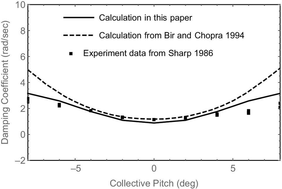
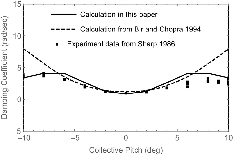
The variations of regressive first lag mode damping versus collective pitch angle for the stiff-flexure and soft-flexure blades are shown in Figs. 3 and 4, respectively. For comparison, the experimental results (Sharp 1986) and the calculated results based on moderate deflection beam theory (Bir and Chopra 1994) are all shown in the figures. For the stiff-flexure blade as shown in Fig. 3, the calculated results in this paper are highly consistent with the experimental results at low absolute value of the collective pitch angle. When the absolute value of the collective pitch angle exceeds about 4°, the calculated results in this paper have a few deviations from the experimental results but still show the same varying trend as the experimental results, i.e., the increase of damping slows down gradually with increasing the absolute value of the collective pitch angle. While the calculated damping based on moderate deflection beam theory increases rapidly with increasing the absolute value of the collective pitch angle. For the soft-flexure blade, the calculated results in this paper agree well with the experimental results as shown in Fig. 4. When the absolute value of the collective pitch angle exceeds about 6°, the calculated results in this paper still agree well with the experimental results and have the same varying trend as the experimental results, i.e., the damping decreases gradually with increasing the absolute value of the collective pitch angle. Whereas the calculated damping based on moderate deflection beam theory increases rapidly with increasing the absolute value of the collective pitch angle, it shows a varying trend contrary to the experimental results. At high absolute values of the collective pitch angle, the torsional deformation of the blade becomes large due to the large airloads. The moderate deflection beam theory approximates the torsional behavior with an ordering scheme, whereas the geometrically exact blade model presented in this paper describes accurately the blade structural behavior including torsional behavior. Hence, an accurate estimation of damping at high absolute values of the collective pitch angle can be obtained by the presented method in this paper, which indicates the necessity of the geometrically exact blade model for calculating the aeroelastic stability of composite rotor blades.
Influence of Transverse Shear Deformation on Aeroelastic Stability
In this section, the influence of transverse shear deformation (TSD) on the aeroelastic stability of five hingeless composite rotors with different elastically coupled blades (Bao et al. 2006, 2008) is investigated. The five hingeless composite rotors have the same main parameters listed in Table 6. The cross section of their blades consists of an IM7/8552 graphite/epoxy D-spar, IM7/8552 graphite/epoxy weave skin, IM7/8552 graphite/epoxy web, Rohacell IG-71 fore cell foam core, and Rohacell IG-31 aft cell foam core. At some spanwise locations of the blade, the tungsten alloy leading-edge weights with airfoil profiles were embedded in the blade to shift the center of gravity of the blade cross section to the aerodynamic center. The five different kinds of elastically coupled blades feature, respectively: zero coupling of flap-bending and torsion (FBT-0), positive coupling of flap-bending and torsion (FBT-P), negative coupling of flap-bending and torsion (FBT-N), two segmented coupling of flap-bending and torsion (FBT-N/P: negative coupling from the root to 75% radius, positive coupling from 75% radius to the tip) and three segmented coupling of flap-bending and torsion (FBT-N/0/P: negative coupling from the root to 55% radius, zero coupling from 55% radius to 75% radius, positive coupling from 75% radius to the tip). These elastic couplings were caused by the D-spar layups of the blades which are listed in Table 7. For the analyses including TSD, the fully coupled cross-sectional stiffness matrix of the blade is obtained from the updated VABS (Hodges 2015). For the analyses ignoring TSD, the flexibility matrix is calculated by the following steps: (1) inverting the fully coupled cross-sectional stiffness matrix calculated by the updated VABS (Hodges 2015) to obtain a flexibility matrix, and (2) replacing the rows and columns corresponding to 1D generalized transverse shear strains in the flexibility matrix with zeroes. In this section, the influence of elastic couplings on the aeroelastic stability of hingeless composite rotors in hover is also calculated, which provides a yardstick for evaluating the influence of TSD.
| Parameter | Value |
|---|---|
| Diameter (m) | 1.8288 |
| Number of blades | 4 |
| Solidity | 0.0943 |
| Speed (rpm) | 2,300 |
| Airfoil | SC-1095 |
| Chord (m) | 0.0677 |
| Component of blade | Layup |
|---|---|
| Skin | [] weave |
| FBT-0 coupled spar | Upper: ; Lower: |
| FBT-P coupled spar | Upper: ; Lower: |
| FBT-N coupled spar | Upper: ; Lower: |
| Web | [] |
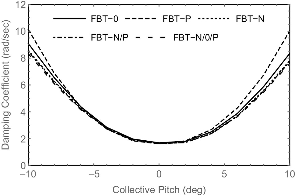
The variations of regressive first lag mode damping versus collective pitch angle for the five hingeless composite rotors in hover are shown in Fig. 5. Fig. 5 illustrates that, at 0° collective pitch angle, the damping is the smallest for all the hingeless composite rotors, and the damping of each hingeless rotor is almost the same, which indicates that the elastic couplings have little influence on damping. As the collective pitch angle increases, the damping increases, and the effect of elastic couplings increases. Moreover, the FBT-N, FBT-P/N, and FBT-P/0/N elastic couplings have similar effects on the lag mode damping. At a collective pitch angle of about 10°, compared with the FBT-0 blade, the FBT-P blade has a 20.0% increase of the damping, the FBT-N, FBT-N/P, and FBT-N/0/P blades have 6.3%, 7.4%, and 9.0% reductions of the damping, respectively. The investigated hingeless composite rotors are small-scale rotors with only four plies in the spar. Therefore, there is limited design flexibility for elastic coupling effects. However, due to the large elastic deformation of the hingeless composite rotor blades, the influence of elastic couplings is still very significant.
The percentage errors of the predicted lag mode damping due to ignoring TSD for these hingeless composite rotors at collective pitch angles of , , 4°, and 8° are listed in Table 8 in which the percentage error is defined as , where and are the predicted lag mode damping ignoring and including TSD, respectively. Table 8 shows that ignoring TSD reduces or increases the lag mode damping for negative or positive collective pitch angles, respectively. The percentage error due to ignoring TSD is the largest at 4° collective pitch angle for all the hingeless composite rotors, with a maximum percentage error of 18%. Comparing the data in Fig. 5 and Table 8, the depicted influence of TSD and elastic couplings are equally important, and both have significant effects on the aeroelastic stability of hingeless composite rotors in hover and cannot be ignored. In Fig. 5, the FBT-N, FBT-P/N, and FBT-P/0/N elastic couplings have similar effects on the lag mode damping. The data listed in Table 8 also have the same trend that the percentage errors of the FBT-N, FBT-P/N, and FBT-P/0/N blades are similar to each other. Therefore, it is inferred that the influence of TSD is related to blade elastic couplings.
| (degrees) | FBT-0 | FBT-P | FBT-N | FBT-N/P | FBT-N/0/P |
|---|---|---|---|---|---|
| 4 | 13.8 | 18.0 | 11.8 | 12.2 | 11.6 |
| 8 | 7.2 | 10.1 | 7.1 | 6.8 | 6.7 |
Influence of Blade Initial Curvatures on Aeroelastic Stability
In this section, the influence of blade initial curvature on the aeroelastic stability of the aforementioned five hingeless composite rotors in hover is investigated. The matrix for the initially curved blades is expressed as
(20)
The vector of coordinates of an arbitrary point on the undeformed blade reference line in the A basis is expressed aswhere subscript 0 indicates the parameter value at , which is usually given; ; = vector of the undeformed blade initial curvature measures in the b basis; ; = blade initial twist; = blade initial out-of-plane curvature; and = blade initial in-plane curvature. Therefore, the blade is straight for ; the blade is only initially twisted for , ; the blade is only initially out-of-plane curved for , , and ; the blade is only initially in-plane curved for , , and ; the blade is both initially out-of-plane and in-plane curved for , ; the blade is initially twisted and curved for . In the following analyses, the blade curvatures ( or ) , , and are used, which produce 2.6°, 5.2°, and 7.8° angles at the blade tip, respectively, for the investigated blades.
(21)
Influence of Initial In-Plane Curvature
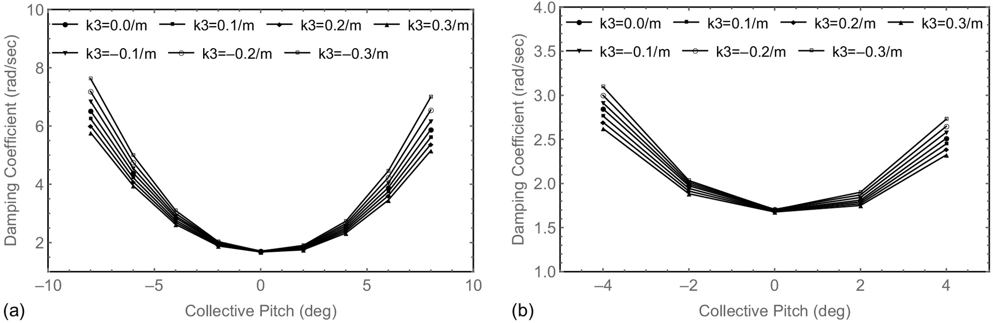
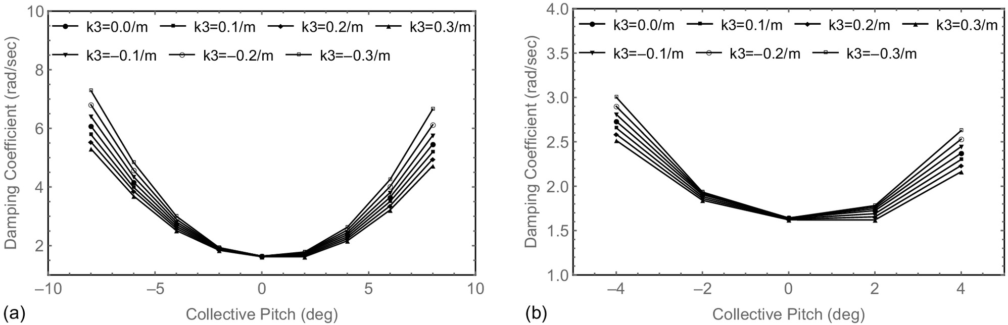
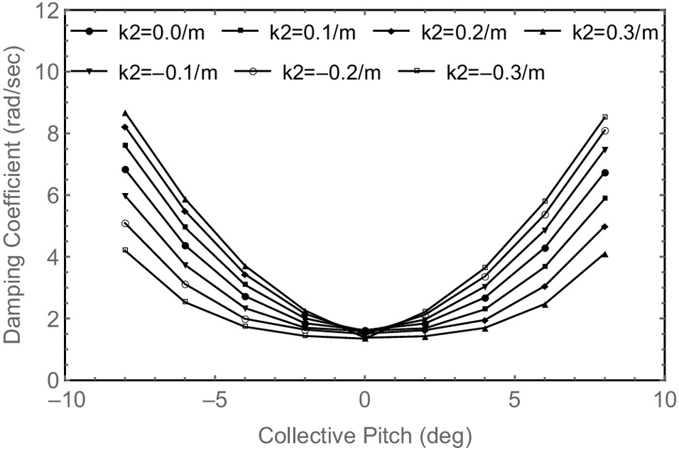
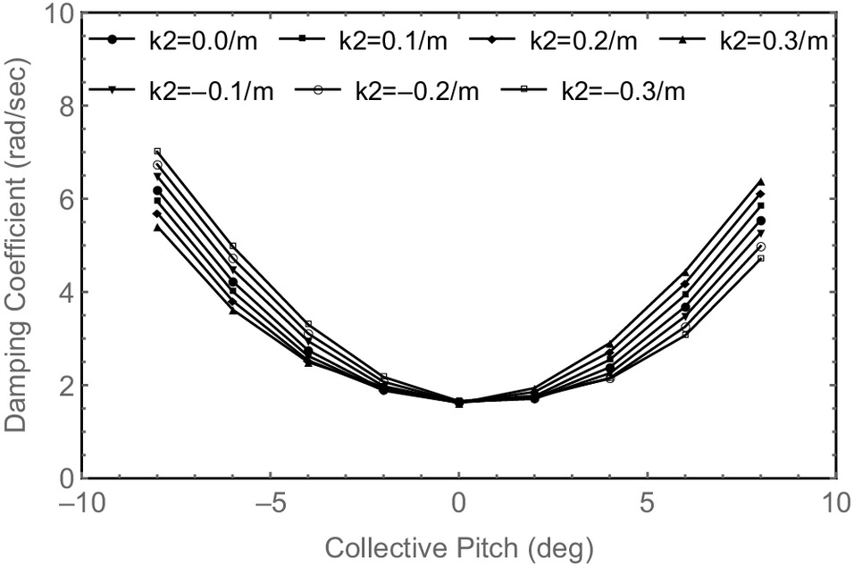
When , , , , the variations of lag mode damping versus collective pitch angle for the five hingeless composite rotors are calculated. The results for the hingeless composite rotors with FBT-0 and FBT-N/0/P blades are shown in Figs. 6 and 7, respectively. To observe these variations more clearly, the variations at collective pitch angles between and 4° are also shown in a separate figure. Similar results are obtained for the FBT-P, FBT-N, and FBT-N/P blades. When , the blade is straight; when , the blade is swept forward; when , the blade is swept back. For each hingeless composite rotor, compared with the straight blade, the negative curvature increases the blade lag mode damping, and the smaller the curvature, the larger the lag mode damping; the positive curvature decreases the blade lag mode damping, and the larger the curvature, the smaller the lag mode damping. When , the blade is swept forward or back, which changes the inertia of the blade bending modes and torsional modes on the one hand and causes additional coupling between the blade flap bending and torsional modes on the other hand. These changes will certainly affect the blade lag mode damping. From Fig. 5, the positive coupling of flap bending and torsion increases the lag mode damping, and the negative coupling of flap bending and torsion decreases the lag mode damping. Therefore, the forward sweep of the blade provides additional negative coupling of flap bending and torsion, and the backward sweep of the blade provides additional positive coupling of flap bending and torsion.
Influence of Initial Out-of-Plane Curvature
When , , , , the variations of lag mode damping versus collective pitch angle for the five hingeless composite rotors are calculated. When , the blade is straight; when , the blade is dihedral; and when , the blade is anhedral. The investigations show that the effect of the initial out-of-plane curvature on the lag mode damping of the FBT-0 and FBT-P blades are similar. As shown in Fig. 8 for the hingeless composite rotors with FBT-P blades, at the positive collective pitch angles, the negative curvature increases the blade lag mode damping, and the smaller the curvature, the larger the lag mode damping; the positive curvature decreases the blade lag mode damping, and the larger the curvature, the smaller the lag mode damping. At the negative collective pitch angles, the negative curvature decreases the blade lag mode damping, and the smaller the curvature, the smaller the lag mode damping; the positive curvature increases the blade lag mode damping, and the larger the curvature, the larger the lag mode damping. In addition, the effect of the initial out-of-plane curvature on the lag mode damping of the FBT-P blade is greater than that of the FBT-0 blade. The predicted results also show that the effect of the initial out-of-plane curvature on the lag mode damping of the FBT-N, FBT-N/P, and FBT-N/0/P blades is similar. As shown in Fig. 9 for the hingeless composite rotors with FBT-N/P blades, at the positive collective pitch angles, the positive curvature increases the blade lag mode damping, and the larger the curvature, the larger the lag mode damping; the negative curvature decreases the blade lag mode damping, and the smaller the curvature, the smaller the lag mode damping. At the negative collective pitch angles, the positive curvature decreases the blade lag mode damping, and the larger the curvature, the smaller the lag mode damping; the negative curvature increases the blade lag mode damping, and the smaller the curvature, the larger the lag mode damping. When , the blade is anhedral or dihedral, which changes the inertia of blade bending modes and torsional modes on the one hand and causes additional coupling between blade lag bending and torsional modes on the other hand. These changes will certainly affect the blade lag mode damping. Overall, the effect of the initial out-of-plane curvature on the lag mode damping of the FBT-N, FBT-P/N, and FBT-P/0/N blades is similar, and the effect on the lag mode damping of the FBT-P and FBT-N blades is totally different. In Fig. 5, the effect of the FBT-N, FBT-P/N, and FBT-P/0/N elastic couplings on the lag mode damping is similar, and the effect of the FBT-P and FBT-N elastic couplings on the lag mode damping is totally different. Therefore, it is inferred that the effect of the initial out-of-plane curvature on the lag mode damping is related to blade elastic couplings.
Influence of Combined Initial Curvature
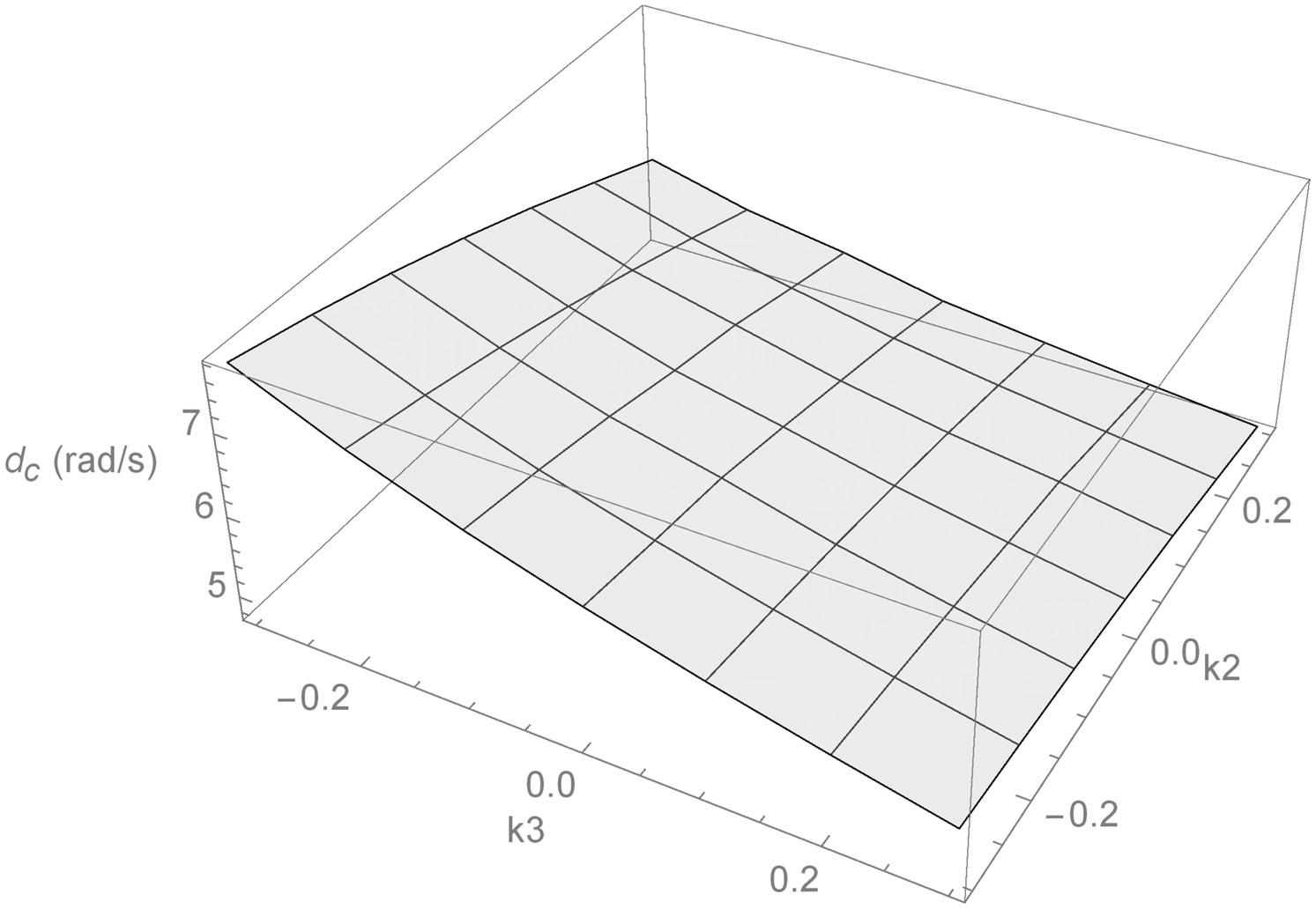
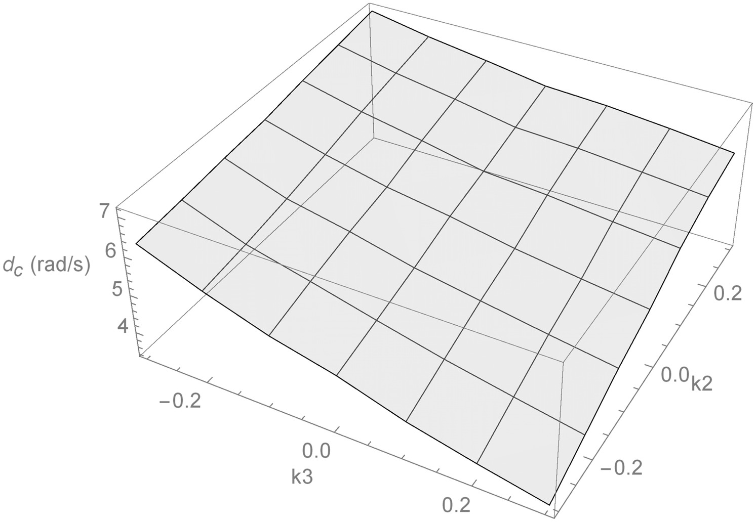
The effect of combined initial in-plane and out-of-plane curvatures on the lag mode damping of the five hingeless composite rotors are investigated. The collective pitch angle = ; the range of the initial out-of-plane curvature = ; and the range of the initial in-plane curvature = . The investigations show that the effect of the combined initial in-plane and out-of-plane curvatures on the lag mode damping of the FBT-0 and FBT-P blades are similar. As shown in Fig. 10 for the hingeless composite rotors with FBT-0 blades, the highest lag mode damping is obtained when and (i.e., the blade is simultaneously anhedral and swept back), and the lowest lag mode damping is obtained when and (i.e., the blade is simultaneously dihedral and swept forward). The predicted results also show that the effect of the combined initial in-plane and out-of-plane curvatures on the lag mode damping of the FBT-N, FBT-N/P, and FBT-N/0/P blades are similar. As shown in Fig. 11 for the hingeless composite rotors with FBT-N blades, the highest lag mode damping is obtained when and (i.e., the blade is simultaneously dihedral and swept back), and the lowest lag mode damping is obtained when and (i.e., the blade is simultaneously anhedral and swept forward). Therefore, a combination of different initial in-plane and out-of-plane curvatures can change the lag mode damping of the investigated hingeless composite rotors, and with appropriate values of these curvatures, the lag mode damping of the blade can be increased.
Conclusions
Accurate methods for geometrically exact aeroelastic stability analysis of composite rotor blades with arbitrary sectional shape and material distribution in hover proposed in this paper have been verified by the experimental results. The calculated results give the following meaningful conclusions.
1.
The Newmark numerical integration method with appropriate numerical damping can eliminate the high-frequency oscillations in the process of time-marching integration of the presented geometrically exact equations of motion and provide an accurate solution in the frequency range of interest.
2.
According to the calculated results, the effect of transverse shear deformation on the aeroelastic stability of the hingeless composite rotor blades in hover cannot be ignored. The change of blade lag mode damping caused by ignoring transverse shear deformation has almost the same magnitude as that caused by elastic couplings.
3.
The blade initial curvatures have significant effects on the aeroelastic stability of the hingeless composite rotors in hover. By choosing appropriate values of the initial in-plane and out-of-plane curvatures, the lag mode damping of the blade can be increased for improving the aeroelastic stability of the composite blades.
Data Availability Statement
Some or all data, models, or code that support the findings of this study are available from the corresponding author upon reasonable request.
Acknowledgments
This study has been supported by the National Natural Science Foundation of China (Grant No. 12002154), the Foundation of National Key Laboratory of Rotorcraft Aeromechanics (Grant No. 61422202203) and the Natural Science Foundation of Jiangsu Province (Grant No. BK20190388).
References
Amoozgar, M. R., and H. Shahverdi. 2019. “Aeroelastic stability analysis of curved composite blades in hover using fully intrinsic equations.” Int. J. Aeronaut. Space Sci. 20 (3): 653–663. https://doi.org/10.1007/s42405-019-00161-w.
Amoozgar, M. R., A. D. Shaw, J. Zhang, and M. I. Friswell. 2019a. “Composite blade twist modification by using a moving mass and stiffness tailoring.” AIAA J. 57 (10): 4218–4225. https://doi.org/10.2514/1.J057591.
Amoozgar, M. R., A. D. Shaw, J. Zhang, and M. I. Friswell. 2019b. “The effect of a movable mass on the aeroelastic stability of composite hingeless rotor blades in hover.” J. Fluids Struct. 87 (May): 124–136. https://doi.org/10.1016/j.jfluidstructs.2019.03.017.
Amoozgar, M. R., A. D. Shaw, J. Zhang, C. Wang, and M. I. Friswell. 2019c. “Lag-twist coupling sensitivity and design for a composite blade cross-section with D-spar.” Aerosp. Sci. Technol. 91 (Jan): 539–547. https://doi.org/10.1016/j.ast.2019.05.053.
Bao, J., V. T. Nagaraj, and I. Chopra. 2006. “Development of Mach scale rotors with tailored composite coupling for vibration reduction.” J. Aircr. 43 (4): 922–931. https://doi.org/10.2514/1.15484.
Bao, J., V. T. Nagaraj, and I. Chopra. 2008. “Wind tunnel test of five sets of Mach scale composite tailored rotor with flap-bending/torsion couplings for vibration reduction.” J. Am. Helicopter Soc. 53 (3): 215–225. https://doi.org/10.4050/JAHS.53.215.
Bauchau, O. A. 1998. “Computational schemes for flexible, nonlinear multibody systems.” Multibody Sys. Dyn. 2 (2): 169–225. https://doi.org/10.1023/A:1009710818135.
Bir, G., and I. Chopra. 1994. University of Maryland advanced rotorcraft code (UMARC) theory manual. College Park, MD: Univ. of Maryland.
Bousman, W. G., and D. J. Winkler. 1981. “Application of the moving-block analysis.” In Proc., Dynamics Specialists Conf., 755–763. Reston, VA: AIAA.
Cesnik, C. E. S. 1994. Cross-sectional analysis of initially twisted and curved composite beams. Atlanta: Georgia Institute of Technology.
Cesnik, C. E. S., and D. H. Hodges. 1997. “VABS: A new concept for composite rotor blade cross sectional modeling.” J. Am. Helicopter Soc. 42 (1): 27–38. https://doi.org/10.4050/JAHS.42.27.
Chung, J., and G. M. Hulbert. 1993. “A time integration algorithm for structural dynamics with improved numerical dissipation: The generalized- method.” J. Appl. Mech. 60 (2): 371–375. https://doi.org/10.1115/1.2900803.
Fulton, M. V., and D. H. Hodges. 1992. “Application of composite rotor blade stability analysis to extension-twist coupled blades.” In Proc., 33rd AIAA/ASME/ASCE/AHS/ASC Structures, Structural Dynamics, and Materials Conf., 1989–1995. Reston, VA: AIAA.
Fulton, M. V., and D. H. Hodges. 1993a. “Aeroelastic stability of composite hingeless rotor blades in hover, part I: Theory.” Math. Comput. Modell. 18 (3–4): 1–17. https://doi.org/10.1016/0895-7177(93)90101-4.
Fulton, M. V., and D. H. Hodges. 1993b. “Aeroelastic stability of composite hingeless rotor blades in hover, part II: Results.” Math. Comput. Modell. 18 (3–4): 19–35. https://doi.org/10.1016/0895-7177(93)90102-5.
He, C. 1989. Development and application of a generalized dynamic wake theory for lifting rotors. Atlanta: Georgia Institute of Technology.
Ho, J. C., D. H. Hodges, and W. Yu. 2010a. “Energy transformation to generalized Timoshenko form for nonuniform beams.” AIAA J. 48 (6): 1268–1272. https://doi.org/10.2514/1.J050160.
Ho, J. C., W. Yu, and D. H. Hodges. 2010b. “Energy transformation to generalized Timoshenko form by the variational asymptotic beam sectional analysis.” In Proc., 51st AIAA/ASME/ASCE/AHS/ASC Structures, Structural Dynamics and Materials Conf., 1–24. Reston, VA: AIAA.
Hodges, D. H. 1990. “A mixed variational formulation based on exact intrinsic equations for dynamics of moving beams.” Int. J. Solids Struct. 26 (11): 1253–1273. https://doi.org/10.1016/0020-7683(90)90060-9.
Hodges, D. H. 2006. “Nonlinear composite beam theory.” Vol. 213 of Progress in astronautics and aeronautics. Reston, VA: AIAA.
Hodges, D. H. 2015. “Unified approach for accurate and efficient modeling of composite rotor blade dynamics.” J. Am. Helicopter Soc. 60 (1): 1–28. https://doi.org/10.4050/JAHS.60.011001.
Hodges, D. H., H. Saberi, and R. A. Ormiston. 2007. “Development of nonlinear beam elements for rotorcraft comprehensive analyses.” J. Am. Helicopter Soc. 52 (1): 36–48. https://doi.org/10.4050/JAHS.52.36.
Jung, S. N., V. T. Nagaraj, and I. Chopra. 2001. “Refined structural dynamics model for composite rotor blades.” AIAA J. 39 (2): 339–348. https://doi.org/10.2514/2.1310.
Jung, S. N., V. T. Nagaraj, and I. Chopra. 2002. “Refined structural model for thin- and thick-walled composite rotor blades.” AIAA J. 40 (1): 105–116. https://doi.org/10.2514/2.1619.
Peters, D. A., D. D. Boyd, and C. He. 1989. “Finite-state induced-flow model for rotors in hover and forward flight.” J. Am. Helicopter Soc. 34 (4): 5–17. https://doi.org/10.4050/JAHS.34.5.
Peters, D. A., and C. He. 1987. “A closed form unsteady aerodynamic theory for lifting rotors in hover and forward flight.” In Proc., 43rd Annual National Forum of the American Helicopter Society, 1–27. Fairfax, VA: American Helicopter Society.
Peters, D. A., M. A. Hsieh, and A. Torrero. 2007. “A state-space airloads theory for flexible airfoils.” J. Am. Helicopter Soc. 52 (4): 329–342. https://doi.org/10.4050/JAHS.52.329.
Popescu, B. 1998. Asymptotically correct refinements in numerical cross-sectional analysis of composite beams. Atlanta: Georgia Institute of Technology.
Shang, L., P. Xia, and D. H. Hodges. 2018. “Geometrically exact nonlinear analysis of pre-twisted composite rotor blades.” Chin. J. Aeronaut. 31 (2): 300–309. https://doi.org/10.1016/j.cja.2017.12.010.
Shang, L., P. Xia, and D. H. Hodges. 2019. “Aeroelastic response analysis of composite blades based on geometrically exact beam theory.” J. Am. Helicopter Soc. 64 (2): 1–14. https://doi.org/10.4050/JAHS.64.022007.
Shang, X. 1995. Aeroelastic stability of composite hingeless rotors with finite-state unsteady aerodynamics. Atlanta: Georgia Institute of Technology.
Shang, X., and D. H. Hodges. 1995. “Aeroelastic stability of composite rotor blades in hover.” In Proc., 36th AIAA/ASME/ASCE/AHS/ASC Structures, Structural Dynamics, and Materials Conf., 2602–2610. Reston, VA: AIAA.
Shang, X., and D. H. Hodges. 1996. “Aeroelastic stability of composite hingeless rotors with advanced configurations.” In Proc., 37th AIAA/ASME/ASCE/AHS/ASC Structures, Structural Dynamics, and Materials Conf., 1991–2001. Reston, VA: AIAA.
Shang, X., D. H. Hodges, and D. A. Peters. 1999. “Aeroelastic stability of composite hingeless rotors in hover with finite-state unsteady aerodynamics.” J. Am. Helicopter Soc. 44 (3): 206–221. https://doi.org/10.4050/JAHS.44.206.
Sharp, D. L. 1986. An experimental investigation of the flap-lag-torsion aeroelastic stability of a small-scale hingeless helicopter rotor in hover. NASA TP-2546. Washington, DC: National Aeronautics and Space Administration.
Yu, W. 2002. Variational asymptotic modeling of composite dimensionally reducible structures. Atlanta: Georgia Institute of Technology.
Yu, W., D. H. Hodges, and J. C. Ho. 2012. “Variational asymptotic beam sectional analysis-an updated version.” Int. J. Eng. Sci. 59 (10): 40–64. https://doi.org/10.1016/j.ijengsci.2012.03.006.
Information & Authors
Information
Published In

Journal of Aerospace Engineering
Volume 37 • Issue 2 • March 2024
Copyright
This work is made available under the terms of the Creative Commons Attribution 4.0 International license, https://creativecommons.org/licenses/by/4.0/.
History
Received: May 15, 2023
Accepted: Sep 19, 2023
Published online: Nov 29, 2023
Published in print: Mar 1, 2024
Discussion open until: Apr 29, 2024
Authors
Metrics & Citations
Metrics
Citations
Download citation
If you have the appropriate software installed, you can download article citation data to the citation manager of your choice. Simply select your manager software from the list below and click Download.