Simulation Study of the Damage Effect of Tandem Warhead on Concrete Target
Publication: ASCE-ASME Journal of Risk and Uncertainty in Engineering Systems, Part A: Civil Engineering
Volume 10, Issue 1
Abstract
The process of a concrete target subjected to a tandem warhead was studied by means of field testing and numerical simulation. First, field testing of a shaped charge impacting the concrete target was carried out, in which the concrete targets included normal strength concrete and ultrahigh performance concrete. Then, the rigid projectile was used to penetrate the damaged concrete targets experimentally. Numerical simulation was adopted to simulate the two stages of a tandem warhead penetrating into the concrete targets. The combined effect of penetration and explosion in the open literature was also reproduced by simulation. By comparing the depth of test data and simulation results, the accuracy of the algorithm, material models, and corresponding parameters was proven. Finally, the numerical simulation method was adopted to simulate the process of a tandem warhead damaging a concrete target, including shaped charge impaction, penetration following the rigid projectile, and explosion inside the concrete. As seen from the comparative results, the parameters used in numerical simulation can appropriately describe the concrete damage, and the tandem warhead can effectively improve the damage degree of concrete targets. The greatest influence of concrete strength on the damage subjected to a tandem warhead is the stage following projectile penetration. The conclusion of this paper can provide important reference significance for the design of tandem warheads and protective engineering.
Introduction
Concrete is widely used in civil and military engineering due to its advantages of cheap materials, easy access, simplicity of manufacturing, and high strength. Compared to normal strength concrete (NSC), the impact resistance, toughness, stability, frost resistance, erosion resistance, permeability resistance, workability, and volumetric stability of ultrahigh performance concrete (UHPC) have been greatly improved. Therefore, UHPC has been widely used in military engineering such as in missile silos, aircraft shelters, weapon depots, military ports, airport runways, air defense buildings, underground command posts, headquarters, etc. In order to improve the weapon’s damage capability, a new type of earth penetration weapon consisting of a precursor shaped charge (SC) and a following kinetic energy (KE) projectile, namely a tandem warhead, has been developed in recent years. When attacking the target, the precursor SC is detonated by the intelligent fuse at an optimal standoff distance (SOD), and a high temperature, high pressure, ultrahigh speed metal is generated to predrill a hole. Subsequently, the following KE projectile advances along the formed hole and continues to penetrate, multiplying the total depth of penetration (DOP). Furthermore, the main charge of following KE projectile explodes subsequently inside the predamaged target to cause greater damage. The tandem warhead can be extensively used for the blockade and destruction of important and valuable targets such as airports, highways, ports, ships, etc.
Most of the existing research focuses on the damage of concrete targets, including the tests of SC into concrete-like targets (Murphy 1983; Wang et al. 2008, 2018; Huerta and Vigil 2006; Murphy et al. 2000, 2003; Esteban et al. 2015; Chen et al. 2023), the theories and simulations of KE projectile penetration into predrilled targets (Murphy 1984; Teland 2001; Bernard 1977; Guo and Wen 2012), as well as the penetration and explosion effects of the projectile in the concrete targets (Sun et al. 2021; Lai et al. 2015; Yang et al. 2018). However, little research has been performed on the full course of destruction of a tandem warhead affecting concrete targets (Heider and Hiermaier 2001; Sohn and Han 2021). For the assessment of concrete target damage, novel methods like acoustic frequency analysis to estimate the materials are worth being explored (Khoshouei et al. 2020; Yari et al. 2019; Yari and Bagherpour 2018a, b).
In this paper, the tests of SC penetrating into NSC and UHPC targets as well as the subsequent rigid projectile penetration into predamaged targets were conducted. The two stages of a tandem warhead attacking concrete targets were reproduced by adopting simulation methods. At the same time, the test in the published literature, including the projectile penetrating into the intact target and explosive exploding inside the predamaged concrete, is also simulated to verify the accuracy of the finite element (FE) model and material parameters and algorithms. On the basis of the verified simulation method, the damage effects of the explosive in the second stage of the tandem warhead exploding inside the predamaged concrete targets is further simulated. Thus the whole process of tandem warhead damage on concrete is studied numerically. Meanwhile, the effect of concrete strength against the tandem warhead is discussed and the damage effects of tandem and KE projectiles on the concrete targets is compared. The conclusions in this article can provide references for the design of protection structures and tandem warheads.
Damage of Concrete Tests
Impact Test of Tandem Warhead
For studying the damage effect of concrete targets subjected to the tandem warhead, an impact test of the tandem warhead was designed and conducted. First, a penetration test of explosively formed projectile (EFP) formed by SC into intact concrete targets was carried out in the field, and then a test of the following rigid projectile penetrating the predamaged concrete targets was carried out indoors.
EFP Impact Test (Hu et al. 2017, 2018)
The SC in the present test consists of the detonator, detonator base, booster, cover plate, explosive, casing, and metal liner (Fig. 1). The thickness of the liner is 1.8 mm. The SC can form a projectile-like metal fragment penetrator with a velocity between and .

The materials of detonator base, cover plate, and casing are 2A12 aluminum alloy, while the explosive in the casing and booster is Comp B. Fig. 2 is the SC with a liner material of T2 copper, of which the total mass is 62.6 g.

Fig. 3 illustrates the schematic diagram and dimensions of NSC and UHPC targets, and the corresponding compressive strengths are 10 MPa and 140 MPa, respectively. The test setup of the SC impact test is illustrated in Fig. 4 in which the standoff distance (SOD) is 70 cm. This test was also performed with a spaced target; see the literature (Hu et al. 2017, 2018) for a detailed test setup and analysis of the results.


Test of the Following Rigid Projectile
As shown in Fig. 5(a), the length, diameter, and total mass of the projectiles used in the test are 152 mm, 25.3 mm and 344 g. The projectiles consist of D6A, which has high strength and can be seen as rigid during the penetration process. Fig. 5(b) shows the dimensions of the projectiles with a length/diameter ratio and caliber-radius-head (CRH) of 6 and 3, respectively. The inert polymer material is filled in the projectile for substituting the filled charge and adjusting the centroid of the projectiles. The projectiles are launched by a smooth-bore powder gun, and the striking velocity is designed between and . Fig. 6 illustrates the setup of the following projectile penetration test, and the projectile can accurately penetrate into the borehole.


In total, the number of targets is 12, of which 8 are NSC and 4 are UHPC. As a comparison, the test of two rigid projectiles penetrating into intact NSC targets and the remaining ten into predamaged targets subjected to EFP is designed, and the detailed test conditions are provided in Table 1.
| Concrete target | No. | Test type | Striking velocity |
|---|---|---|---|
| NSC | I-8, I-11 | Projectile | , |
| NSC | I-1, I-2, I-5, I-6, I-7, I-9 | Tandem warhead | , , |
| UHPC | V-1–V-4 | Tandem warhead | , |
Test Results
The sketch of damaged targets subjected to EFP and the following projectile (combined damage effect) is illustrated in Fig. 7, in which the is the increasing depth caused by the subsequent projectile individually, and Table 2 lists the corresponding test data (Hu et al. 2017, 2018).

| No. | () | DOP (cm) | (cm) | |
|---|---|---|---|---|
| EFP | Projectiles | |||
| I-1 | 298 | 12.0 | 20.0 | 8.0 |
| I-2 | 305 | 11.0 | 23.0 | 12.0 |
| I-5 | 417 | 11.6 | 30.1 | 18.5 |
| I-6 | 418 | 12.5 | 33.7 | 21.2 |
| I-7 | 500 | 13.8 | 43.3 | 29.5 |
| I-9 | 504 | 14.1 | 43.8 | 29.7 |
| I-8 | 300 | — | 17.2 | 17.2 |
| I-11 | 498 | — | 31.3 | 31.3 |
| v-1 | 305 | 7.6 | 9.9 | 2.3 |
| V-2 | 308 | 8.1 | 10.6 | 2.5 |
| V-3 | 500 | 8.0 | 15.7 | 7.7 |
| V-4 | 504 | 9.0 | 15.3 | 6.3 |
Penetration and Explosion Test (Sun et al. 2021)
In order to study the influence of penetration hole contour on the effect of inside explosion, Sun et al. (2021) carried out a test of explosion after penetration in plain concrete. The test consists of two stages, in which the concrete targets are normally penetrated by the projectile first, and then the explosive was placed at the bottom of the penetration tunnel area for the explosion test after removing the projectile.
Penetration Test
As shown in Fig. 8, the penetration test of projectile [Fig. 8(a)] and the target [Fig. 8(b)] are illustrated. The cylindrical targets with strengths of about 30 MPa and 40 MPa were used, in which the diameters were 0.8 m and thicknesses were 0.5 m (Sun et al. 2021). The shape of the projectile used is ogive-nosed, with a diameter, length, mass, CRH, and material composition of 20 mm, 100 mm, 168 g, 2.5, and 30CrMnSiNi2A steel, respectively. The strength of the projectile nose is about 1.5 GPa, and the range of test velocity is .

Internal Explosion Test
After the penetration test, the projectiles were removed from the penetration hole, and the damaged targets were moved outside. The predesigned explosive was loaded into the bottom of the penetration tunnel for the explosion test, see Fig. 9(a) (Sun et al. 2021). It should be noted that the explosive at the penetration bottom is filled with concrete in the fifth shot. The hexogen (RDX) explosive with detonation velocity of and detonation energy of was adopted. In order to adjust the charge, the explosive was made into a pillar with a 20-mm diameter, 20-mm thickness and 7.85 g, as shown in Fig. 9(b) (Sun et al. 2021). For each shot, the explosive consists of five superimposed pillars, and the total mass is 39.25 g.

Penetration and Explosion Test Results
The number of explosions after the penetration test is 10, in which the number of 30 MPa targets is six, and that of 40 MPa is four. The velocity in the test is designed between 479.2 and , and the total mass of the explosive is 39.25 g. Both the DOP of projectile penetrating and the subsequent explosion are listed in Table 3, where illustrates the net increase in DOP from the explosion test.
| No. | Target materials | Velocity () | DOP (cm) | (cm) | |
|---|---|---|---|---|---|
| Penetration | Explosive | ||||
| 1 | C30 | 479.20 | 21.1 | 23.1 | 2 |
| 2 | C30 | 488.73 | 22.1 | 24.6 | 2.5 |
| 3 | C30 | 512.37 | 22.6 | 25.6 | 3 |
| 4 | C30 | 525.27 | 23.2 | 26.3 | 3.1 |
| 5 | C30 | 551.13 | 26.7 | — | — |
| 6 | C30 | 567.47 | 26.2 | 29.5 | 3.3 |
| 7 | C40 | 548.82 | 22.5 | 24.1 | 1.6 |
| 8 | C40 | 566.25 | 23.4 | 25.5 | 2.1 |
| 9 | C40 | 612.52 | 25.3 | 29.9 | 2.5 |
| 10 | C40 | 675.75 | 27.9 | 31.5 | 3.6 |
Numerical Simulations and Comparisons
Finite-Element Model and Materials Parameters
To solve the problem using the Lagrange algorithm can result in severe distortions in large deformation calculations and the Euler algorithm cannot describe the material interface accurately; therefore, Ramaswamy and Kawahara (1987) and Hureta and Liu (1988) developed the multimaterial arbitrary Lagrange-Euler (ALE) algorithm. The ALE algorithm includes advantages of both Lagrange and Euler algorithms. Via the ALE algorithm, the shape and material interface of the continuous substance can be described and the serious distortions are avoided, thereby the high strain rate, high pressure, and nonlinear deformation characteristics can be simulated, accurately. The structured ALE (S-ALE) algorithm was embedded into the commercial FE software LS-DYNA in 2015. The S-ALE solver has exactly the same theoretical basis as the original ALE and uses the same transport and interface reconstruction algorithm. The S-ALE has advantages of simpler mesh generation, less memory required, 20%–40% less computation time, and higher parallel efficiency than the traditional ALE algorithm. In order to numerically reproduce the penetration of the following rigid projectile into the predamaged concrete targets subjected to the EFP, and the explosion in predamaged concrete target by projectiles, the restart input data method, which can divide the complete analysis process into multiple stages and carry over by a restart file, is used.
The damage effects of the tandem warhead to concrete targets includes three steps: precursor EFP forming and impacting concrete targets, following projectile penetrating into the predamaged concrete, and main explosive exploding inside the predrilled target. It includes explosive explosion, energy transfer, blast drive, hypervelocity impact, penetration of KE projectile, internal explosion, and structural damage, etc. In addition, it is a process that includes multiple substances, large deformation, high strain rate, and ultrahigh load.
EFP Impact Simulation
The test setup can be seen as axisymmetric and the model is adopted to reduce the time of computer calculation. Fig. 10 shows the FE model and meshes of SC impacting on concrete target (units in ). The symmetric boundary condition is applied on the symmetric surface of the model. Meanwhile, the non-reflect boundary is applied around the target for the stress wave not reflecting when it reaches the target boundary, therefore the model excludes the steel culvert. In this simulation, the materials of air, explosives, liners, and casings are described by the multimaterial ALE algorithm, while the concrete materials are computed by the Lagrange algorithm. The interaction between the EFP and targets is calculated using the Fluid-Structure Interaction (FSI) method, which can efficiently solve problems relative to the interaction between the fluid and structures. As shown in Fig. 10, the penetration of EFP into the target is realized through coupling the Lagrange and ALE grids, thus the partial air and target grids are overlapped.

Simulation of Projectile Penetration
As a continuation of the section “EFP Impact Simulation,” by using the restart input data method which is embedded in LS-DYNA (2001), the penetration test of following projectiles into the predamaged concrete targets is carried out numerically. Similarly, considering that the test setup (Figs. 1–6) is axisymmetric and reduces the time of computer calculation, the model is adopted. Fig. 11 illustrates the FE models and grids of the concrete targets in the tandem warhead impact experiment [Fig. 11(a)]. Fig. 11(b) illustrates the FE models mesh of projectiles into intact concrete in the penetration and explosion test (Sun et al. 2021). The projectiles and concrete targets are computed with the Lagrange algorithm. The keyword *CONTACT_ERODING_SURFACE_TO_SURFACE is used to define the contact behavior between rigid projectiles and concrete targets.

Internal Explosion
As a continuation of the section “Simulation of Projectile Penetration” [model in Fig. 11(b)], by adopting the restart input data method, the internal explosion inside concrete target after rigid projectile penetration is simulated in a similar way. Fig. 12(a) shows FE models of internal explosion inside concrete target, and it should be noted that the model consists of air and target, in which the explosive is calculated by S-ALE algorithm. Thus, Fig. 12(b) gives the generated ALE grids of explosive materials, in which the air is not displayed.

Constitutive Models and Materials Parameters
Air
The air material is described by the NULL material model (*MAT_NULL ()) and linear polynomial equation of state (EOS), which relates the pressure with aswhere = equation constants; and = energy per unit volume. The parameters used for air are given in Table 4.
(1)
| Density, () | Coefficients | Energy per unit volume, () | ||||||
|---|---|---|---|---|---|---|---|---|
| 1.293 | 0 | 0 | 0 | 0 | 0.4 | 0.4 | 0 | |
Source: Data from Alia and Souli (2006).
Explosives
The material of explosive is described by material model [*MAT_HIGH_EXPLOSIVE_BURN ()] and Jones-Wilkens-Lee (JWL) EOS. The JWL EOS can describe the relationship of the pressure, volume, and energy of detonation products aswhere , , , , and = materials constants; = detonation energy per unit volume; and = relative volume. The materials parameters of Comp B, TNT, and RDX are shown in Table 5.
(2)
Metallic Materials
The Johnson-Cook (JC) material model (Johnson and Cook 1983) [*MAT_JOHNSON_COOK ()] is used to describe the liner and casing materials. The JC model can also describe the strength behavior of the metallic materials subjected to large strains, high temperatures, and high strain rates, which is expressed aswhere , , , , and = materials constants; and and = flow stress and effective plastic strain, respectively. illustrates the normalized effective plastic strain rate and illustrates reference plastic strain rate. is homologous temperature, and the and denote the melting and room temperatures, respectively.
(3)
The EOS of Gruneisen is adopted to describe the metallic material under high strain rate (), in which the pressure of materials under compressed conditions is expressed as (LS-DYNA 2001)
(4)
While for the expanded condition, the pressure is given as (LS-DYNA 2001)where denote the curve intercept of the , units in , while the and indicate the cubic shock velocity and particle velocity, respectively. The , , and variables denote the dimensionless curve slope coefficients of . denotes the volumetric strain, while and represent the current and initial densities, respectively. = internal energy; = dimensionless Gruneisen parameter; and = corresponding first-order volume correction. As shown in Table 6, the parameters of SC liner and casing are listed.
(5)
| Parameters | T2 copper | 2A12 aluminum |
|---|---|---|
| Density, () | 8,960 | 2,785 |
| Yield strength, (MPa) | 90 | 265 |
| Hardening modulus, (MPa) | 292 | 426 |
| Hardening coefficient, | 0.31 | 0.34 |
| Strain rate sensitivity coefficient, | 0.025 | 0.015 |
| Thermal softening coefficient, | 1.09 | 1.0 |
| Melting temperature, (K) | 1,356 | 775 |
| Room temperature, (K) | 293 | 293 |
| Intercept, () | 3,940 | 5,328 |
| Coefficient, | 1.49 | 1.34 |
| Coefficient, | 0.6 | 0 |
| Coefficient, | 0 | 0 |
| Gruneisen parameter, | 1.99 | 2.0 |
| Constant, | 0.47 | 0 |
| Internal energy, (J) | 0 | 0 |
Source: Data from ANSYS/Autodyn-2D and 3D (2007).
Concrete Targets
In 1999, Riedel et al. (1999) proposed the RHT (Riedel-Hiermaiser-Thoma) constitutive model for concrete, which introduced pressure-related elastic limit surfaces, failure surfaces, and residual strength surfaces, as shown in Fig. 13. The variation patterns of the initial yield strength, failure strength, and residual strength of the materials are described. The RHT concrete model (Riedel et al. 1999) can describe the irreversible deformation of certain zones of the concrete materials under impact load, thus the RHT model is adopted to calculate the concrete targets in the tandem warhead impact test and the penetration and explosion test in this paper.

The RHT model is divided into three phases, i.e., elastic phase, linear hardening phase, and damage weakening phase, as shown in Fig. 14. The relevant equations involved in the three phases are as follows:
1.
Failure surface equation
The failure surface stress strength of the material is usually determined experimentally in the quasi-static loading mode. In the RHT constitutive model, the normalized pressure is introduced to eliminate the effect of the concrete strength grade, and the failure stress strength is calculated as follows:where = quasi-static uniaxial compressive strength; = quasi-static failure surface compression meridian equivalent force strength; = lode angle parameter; = dynamic amplification factor; and is the quasi-static pressure.
(6)
2.
Elastic limit surface equation
The elastic limit surface equivalent force of the material is deduced from the equivalent stress of the failure surface, and the elastic limit stress strength is calculated as follows:where and represent elastic compression function and the “cap” function, respectively; and is the quasi-static elastic limit pressure.
(7)
3.
Damage weakening function
The advantage of the RHT dynamic constitutive model is that it gives the softening equation after damage while defining the material strain hardening effect, and is able to simulate the softening effect of material damage in concrete materials after the equivalent stress strength exceeds the failure stress strength. The damage variable is defined as the ratio of the cumulative equivalent plastic strain increment to the final failure equivalent plastic strainwhere = increment of equivalent plastic strain; and denotes the plastic strain when the concrete fails. The concrete parameters of the RHT model used in this paper are listed in Table 7.
(8)

| Parameters | NSC | NSC | UHPC |
|---|---|---|---|
| Shear modulus (GPa) | 4.447 | 26.8 | 16.6 |
| Compressive strength () | 10 | 140 | |
| Tensile strength () | 0.1 | 0.1 | 0.1 |
| Shear strength () | 0.18 | 0.18 | 0.18 |
| Intact failure surface constant A | 1.6 | 1.4 | 1.6 |
| Intact failure surface exponent N | 0.61 | 0.61 | 0.61 |
| Tens./Comp. meridian ratio (Q) | 0.6805 | 0.6805 | 0.6805 |
| Brittle to ductile transition | 0.0105 | 0.0105 | 0.0105 |
| G (elastic)/(elastic–plastic) | 2 | 2 | 2 |
| Elastic | 0.7 | 0.7 | 0.7 |
| Elastic | 0.53 | 0.53 | 0.53 |
| Fractured strength constant B | 0.7 | 0.7 | 1.6 |
| Fractured strength exponent M | 0.8 | 0.8 | 0.61 |
| Compressive strain rate exponent | 0.032 | 0.032 | 0.00909 |
| Tensile strain rate exponent | 0.036 | 0.036 | 0.0125 |
| Max. fracture strength ratio | 1.0 × 10²⁰ | 1.0 × 10²⁰ | 1.0 × 10²⁰ |
| Erosion strain | 1 | 1 | 1 |
| Reference density () | 2,750 | 2,750 | 2,750 |
| Porous density () | 2,300 | 2,400 | 2,500 |
| Porous sound speed () | 2,920 | 2,920 | 3,242 |
| Initial compaction pressure (MPa) | 23.3 | 23.3 | 9.33 |
| Solid compaction pressure (GPa) | 5.999 | 5.999 | 6 |
| Compaction exponent | 3 | 3 | 3 |
| Bulk modulus, (GPa) | 35.27 | 35.27 | 35.27 |
| Parameter, (GPa) | 39.58 | 39.58 | 39.58 |
| Parameter, (GPa) | 9.04 | 9.04 | 9.04 |
| Parameter B0 | 1.22 | 1.22 | 1.22 |
| Parameter B1 | 1.22 | 1.22 | 1.22 |
| Parameter, (GPa) | 35.27 | 100 | 35.27 |
| Parameter, (GPa) | 0 | 0 | 0 |
| Reference temperature (K) | 300 | 300 | 300 |
| Specific heat () | 654 | 654 | 654 |
| Thermal conductivity (W/mk) | 0 | 0 | 0 |
Comparison of the Test Data and Simulation Result
EFP Impacts on the Concrete Targets
Fig. 15 shows the progress of T2 copper EFP forming and flying. When the shock wave and gaseous product produced by the detonation of the explosive arrive, the metallic liner is wrapped and accelerated with the high-speed EFP penetrator forming. Taking the NSC target as an example, Fig. 16 further illustrates the process of EFP impacting on the NSC target with compressive strength of 10 MPa. When the penetration depth does not increase further, the penetration process terminates by generating a restart file named “d3dump”, which saves the results of the previous calculation, and can be used for subsequent rigid projectile penetration simulation.


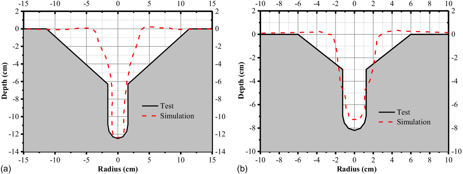
Fig. 17 gives the simulation results of the EFP impacting the NSC and UHPC targets, in which the concrete is described by RHT model. The dimensions of DOP and spalling crater are illustrated graphically. Furthermore, Fig. 18 shows comparisons of the terminal damage contour map of NSC and UHPC targets, in which the black solid lines represent the average test data and the red dashed lines represent the simulation results of RHT models. This indicates that the simulated results agree well with the test data. Thus, it can be verified that the adopted simulation methods, the constitutive models, and corresponding materials parameters are appropriate.

Following Projectile Penetration into Predamaged Concrete Targets
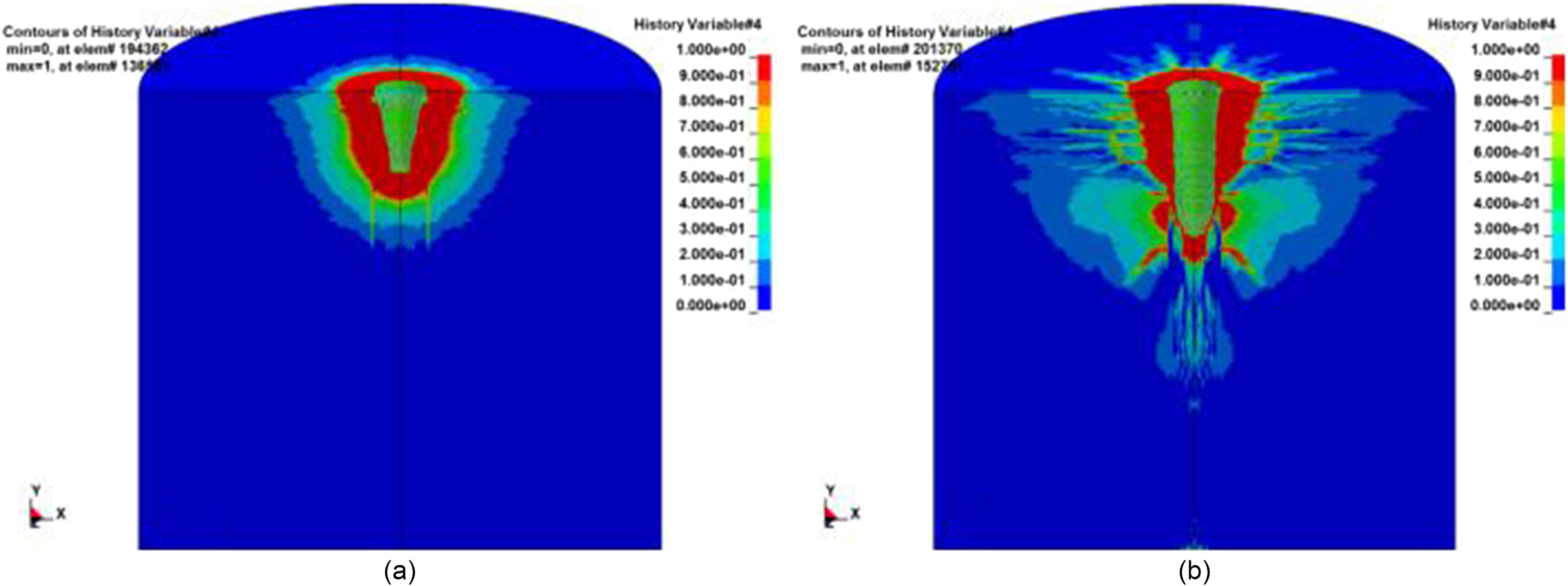
Similarly, taking the NSC target with an impact velocity of for example, Fig. 19 gives the typical process of following projectile penetration into the predamaged concrete target subjected to the EFP (Fig. 16). The projectile penetrates into the predamaged target vertically, while the projectile velocity decreases to zero and a restart file generates the penetration process ends. Fig. 20 further gives damage contours of the target before and after the projectile impact, which represents the target damage subjected to EFP and tandem warhead, respectively. It is seen that the damage of the concrete target induced by EFP [Fig. 20(a)] is recorded and further aggravated by the following rigid projectile impacting [Fig. 20(b)].

The simulation results of EFP penetrating into the concrete target were shown and evaluated in the section “EFP Impacts on the Concrete Targets.” Furthermore, Table 8 compares the impact test data and simulation results of the tandem warhead (DOP) and individual following projectile (), in which the average test data is from Table 2. In addition, the simulation results of projectile penetration into the intact NSC targets are listed, and it should be noted that refers to the depth caused by the individual projectile. Considering the largest deviation is just 9.9%, good agreement is derived for the final DOP. Thus, the restart input data method, the adopted constitutive models, and materials parameters are proven to be appropriate.
| Target type | () | DOP (cm) | (cm) | ||||
|---|---|---|---|---|---|---|---|
| Experiment | Simulation | Deviation (%) | Experiment | Simulation | Deviation (%) | ||
| I | 300 | 21.5 | 21.5 | 0 | 10.0 | 9.2 | 8.0 |
| I | 400 | 31.9 | 32.8 | 2.8 | 19.9 | 20.5 | 3.0 |
| I | 500 | 43.6 | 39.3 | 9.9 | 29.6 | 27 | 8.8 |
| I | 300 | — | — | — | 17.2 | 18.0 | 4.7 |
| I | 500 | — | — | — | 31.3 | 30.3 | 3.2 |
| V | 300 | 10.3 | 9.9 | 3.9 | 2.4 | 2.6 | 8.3 |
| V | 500 | 15.5 | 14.5 | 6.5 | 7.0 | 7.2 | 2.9 |
Rigid Projectile Penetration into Concrete Targets in Penetration and Explosion Test
Fig. 21 illustrates the simulation penetrating process of projectile into the intact concrete target. Similarly, the penetration process terminates with penetration depth not increasing and a restart file generated. Table 9 lists the tolerance of simulation results and test data. It can be seen that the simulation results and the test data are in good agreement for the largest difference of 7.5%, thus the constitutive model and materials parameters, especially C30 and C40 concrete, are verified.

| Target | () | DOP (cm) | ||
|---|---|---|---|---|
| Experiment | Simulation | Deviation (%) | ||
| C30 | 479.20 | 21.1 | 21.4 | 1.4 |
| C30 | 488.73 | 22.1 | 21.6 | 2.3 |
| C30 | 512.37 | 22.6 | 23.1 | 2.2 |
| C30 | 525.27 | 23.2 | 24.3 | 4.7 |
| C30 | 551.13 | 26.7 | 25.3 | 5.2 |
| C30 | 567.47 | 26.2 | 26.2 | 0 |
| C40 | 548.82 | 22.5 | 21.6 | 4.0 |
| C40 | 566.25 | 23.4 | 23.9 | 2.1 |
| C40 | 612.52 | 25.3 | 26.3 | 3.9 |
| C40 | 675.75 | 27.9 | 30 | 7.5 |
Internal Explosion inside Concrete Targets
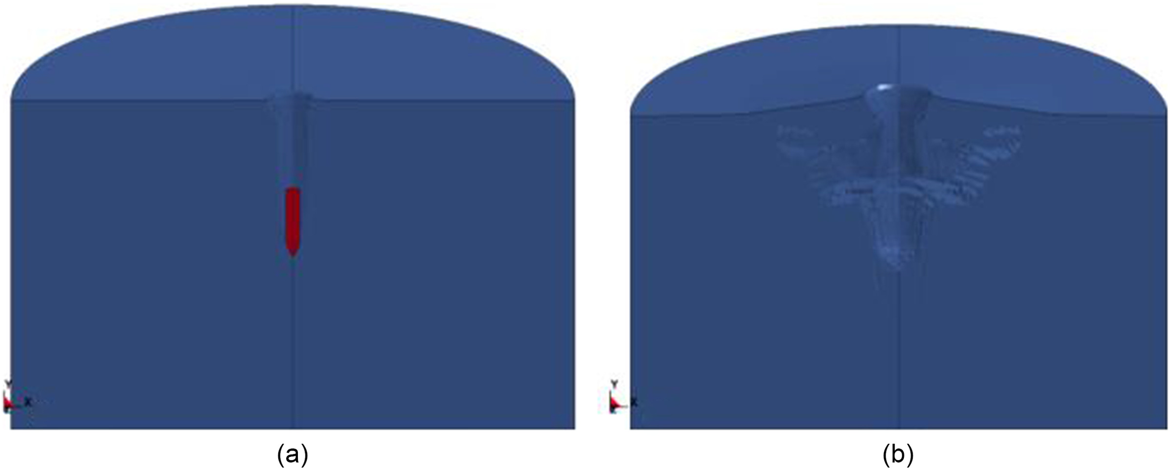
Based on the section “Rigid Projectile Penetration into Concrete Targets in Penetration and Explosion Test,” the explosions inside predamaged concrete targets are further simulated by using the restart algorithm. Taking the C30 target with a striking velocity of as an example, Fig. 22 gives the concrete damage caused by the rigid projectile impacting and combined effect of projectile and explosive. Table 10 further compares the simulation results and test data of the combined effect of penetration and explosion (DOP) and individual internal explosion (), in which the test data is from Table 3. It can be seen that the experimental data and numerical simulation results are in very good agreement, because the maximum difference of DOP is only 12%. While the difference of between the experiment and simulation is great, the reason is that the absolute value of the increase is too small. The constitutive model and materials parameters of C30 and C40 are further verified.
| Target type | () | DOP (cm) | (cm) | ||||
|---|---|---|---|---|---|---|---|
| Experiment | Simulation | Deviation | Experiment | Simulation | Deviation | ||
| C30 | 479.20 | 23.1 | 24.2 | 4.7% | 2 | 2.8 | 40% |
| C30 | 488.73 | 24.6 | 24.6 | 0 | 2.5 | 3 | 20% |
| C30 | 512.37 | 25.6 | 27.9 | 8.9% | 3 | 4.8 | 60% |
| C30 | 525.27 | 26.3 | 28.1 | 6.8% | 3.1 | 3.8 | 22.5% |
| C30 | 551.13 | — | — | — | — | — | — |
| C30 | 567.47 | 29.5 | 30.0 | 1.6% | 3.3 | 3.8 | 15.2% |
| C40 | 548.82 | 24.1 | 24.5 | 1.7% | 1.6 | 2.9 | 81.3% |
| C40 | 566.25 | 25.5 | 27.1 | 6.2% | 2.1 | 3.2 | 52.4% |
| C40 | 612.52 | 29.9 | 30.9 | 3.3% | 2.5 | 4.6 | 0 |
| C40 | 675.75 | 31.5 | 35.3 | 12% | 3.6 | 5.3 | 47.2% |
Damage Effect of Tandem Warhead on Concrete
In the above sections, the penetration process of tandem warhead into concrete, which consists of the SC impaction on intact concrete target and the following projectile penetration along the hole induced by EFP, was simulated. Meanwhile the concrete damage caused by previous rigid projectile and subsequent internal explosion is simulated. The simulation work was carried out to verify the adopted FE models, constitutive models, algorithms, and corresponding material parameters. In this section, the whole process of tandem warhead damaging the concrete targets, which consists of SC, following, and mean explosive, is further studied by simulation method, i.e., a third stage is added.
Simulation of the Process of a Tandem Warhead Damaging a Concrete Target
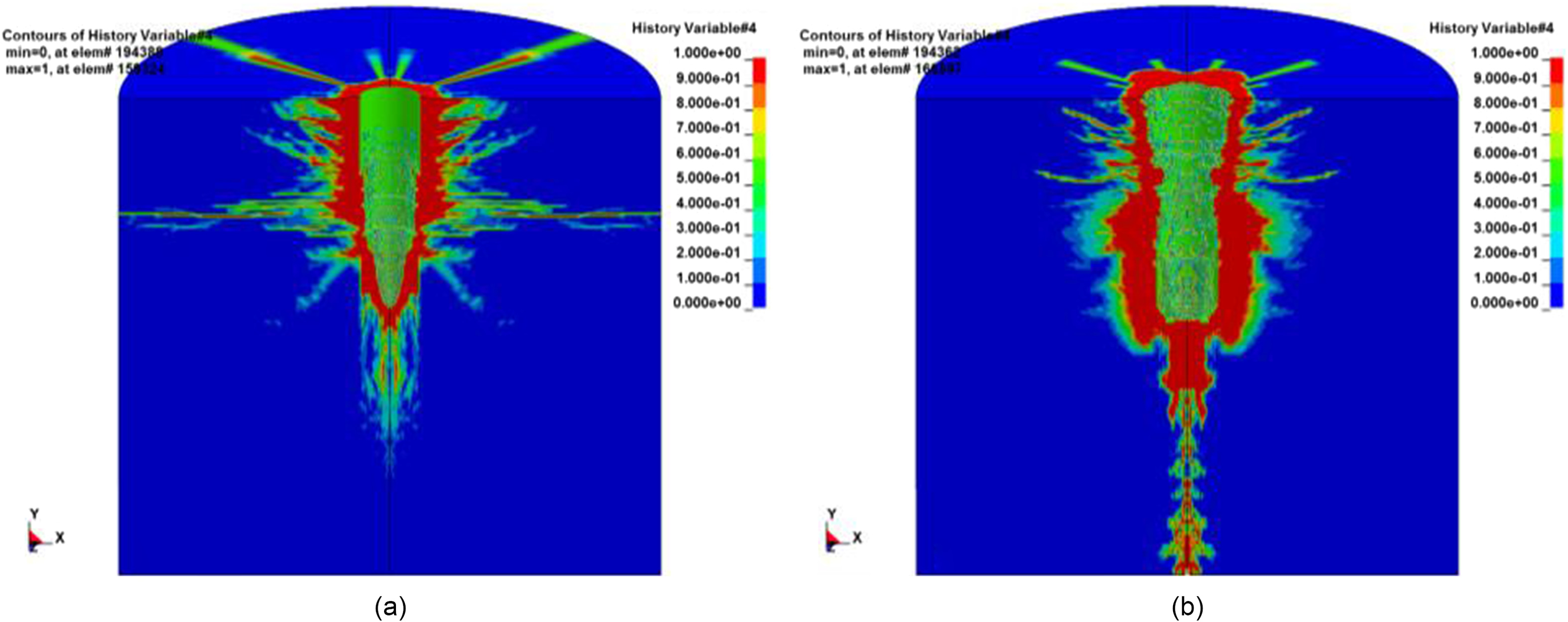
Based on the simulation of the section “Numerical Simulations and Comparisons,” the third stage of exploding inside the damaged concrete targets caused by a rigid projectile is added, where the concrete target with compressive strength of 40 MPa is added. Fig. 23 gives concrete target damage of the three different stages of tandem warhead impact, in which the compressive strength is 10 MPa and the impacting velocity is . As a comparison, the projectile with subsequent internal explosion inside concrete is given simultaneously, shown in Fig. 24. In order to be consistent with the test setup in the section “Impact Test of Tandem Warhead,” the explosive used in the third stage is TNT with a diameter of 16 mm and a length of 10 cm, thus the total quality of the main explosive is . Similarly, the explosive is modeled using the S-ALE algorithm.

Comparison of Individual KE Projectile and Tandem Warhead
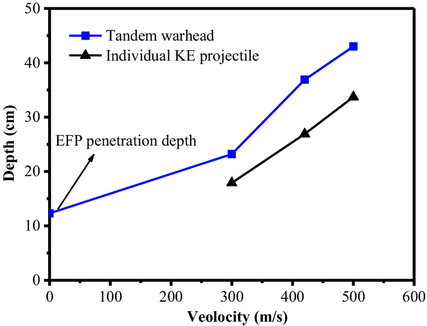
Fig. 25 shows the total damage effect (depth) of the tandem warhead and individual KE projectile on the concrete target of 10 MPa at different velocities via simulation. As stated in the above sections, the masses of the SC, following projectile, and main explosive are 62.6 g, 344 g, and 32.8 g, thus the weight of SC is just 16.6% of the following KE projectile, while the total DOP increases by 27.6% to 37.2% with a striking velocity between and .
Influence of Concrete Strength against the Tandem Warhead
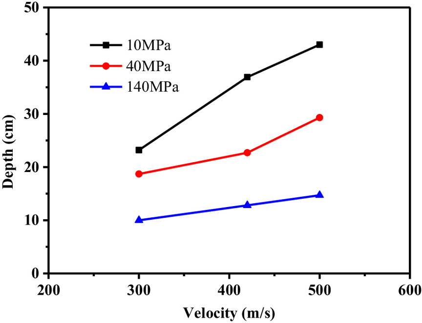
For studying the effect of concrete strength against the tandem warhead, Fig. 26 gives the simulated concrete target damage in the three different stages, in which the compressive strengths of concrete targets are 10 MPa, 40 MPa, and 140 MPa, respectively. It can be seen that with increasing concrete strength, the damage degree of the tandem warhead on concrete targets is less. The damage depth of tandem warhead on the UHPC target is 34.2%–43.1% and 50.2%–56.4% of those of NSC targets with 10 MPa and 40 MPa; thus, the UHPC plays an obvious role in resisting the tandem warhead.
Influence of Concrete Strength on Different Stages of Tandem Warhead Impact
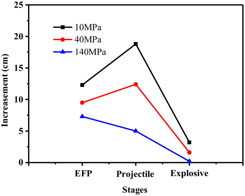
Fig. 27 illustrates the influence of concrete strength on different stages of the tandem warhead impacting on concrete targets. It can be seen that with increasing concrete strength, the damage degree in all three stages decreases. It can be also concluded that the concrete strength influence is greatest in the stage of following projectile penetration, which is the same conclusion as KE projectile penetration.
Conclusion
Based on the impact experiment of tandem warhead (a precursor EFP and a subsequent projectile) on concrete targets, as well as the penetration and explosion test, the whole process of a concrete target subjected to a tandem warhead was studied by experiment and simulation methods. The tandem warhead impact test with 12 shots was conducted, in which two were the individual projectiles. Both the tandem warhead impact test as well as the penetration and explosion test are simulated by using the restart input data method implemented in the FE program LS-DYNA. The influences of concrete strength and the following projectile striking velocity on the damage effect by tandem warhead are compared. For the condition discussed in this article, the main conclusions can be derived as follows:
1.
The tandem warhead has prominent impact performance, since the damage depth of the tandem warhead into NSC targets increases, on average, by 27.6% to 37.2% in comparison to the individual KE projectile;
2.
UHPC targets shows much higher impact resistance, considering that the damage depths of the tandem warhead into UHPC targets are 34.2%–43.1% and 50.2%–56.4% of those into NSC targets with strengths of 10 MPa and 40 MPa, respectively;
3.
The greatest influence of concrete strength on the stage of tandem warhead impacting on the concrete targets is the penetration of the following projectile.
The conclusion of this article has important reference significance for the design of tandem warhead and protective engineering.
Data Availability Statement
The experimental data that support the simulation works and the findings of this study are openly available in literature Hu et al. (2017, 2018) and Sun et al. (2021). Some or all data, models, or code generated or used during the study are available in a repository or online in accordance with funder data retention policies.
Acknowledgments
The project was supported by the National Natural Science Foundation of China (12102476).
References
Alia, A., and M. Souli. 2006. “High explosive simulation using multi-material formulations.” Appl. Therm. Eng. 26 (10): 1032–1042. https://doi.org/10.1016/j.applthermaleng.2005.10.018.
ANSYS/Autodyn-2D and 3D. 2007. ANSYS/Autodyn-2D and 3D, version 6.1. User documentation. Canonsburg, PA: ANSYS.
Bernard, R. S. 1977. Empirical analysis of projectile penetration in rock. Vicksburg, MS: US Army Waterways Experiment Station.
Chen, J.-Y., D.-L. Feng, Q.-Y. Sun, C. Peng, Y.-H. Zhu, and S.-Y. Yu. 2023. “Numerical modeling of shaped charge jet penetration into ceramic–metal double-layered medium using smoothed particle hydrodynamics.” Int. J. Impact Eng. 175 (May): 104526. https://doi.org/10.1016/j.ijimpeng.2023.104526.
Esteban, B., L. M. Lenhart, L. Rüdiger, and N. Gebbeken. 2015. “An evaluation of shaped charge experiments using concrete components.” Int. J. Prot. Struct. 6 (3): 439–455. https://doi.org/10.1260/2041-4196.6.3.439.
Guo, X. J., and H. M. Wen. 2012. “Performance analysis and optimization of a dual warhead system.” Int. J. Nonlinear Sci. Numer. Simul. 13 (1): 49–54. https://doi.org/10.1515/ijnsns-2011-100.
Heider, N., and S. Hiermaier. 2001. “Numerical simulation of the performance of tandem warheads.” In Proc., 19th Int. Symp. on Ballistics, 1493–1499. San Antonio: International Ballistics Society.
Hu, F., H. Wu, Q. Fang, and J. C. Liu. 2018. “Impact resistance of concrete targets predamaged by explosively formed projectile (EFP) against rigid projectile.” Int. J. Impact Eng. 122 (Dec): 251–264. https://doi.org/10.1016/j.ijimpeng.2018.08.014.
Hu, F., H. Wu, Q. Fang, J. C. Liu, B. Liang, and X. Z. Kong. 2017. “Impact performance of explosively formed projectile (EFP) into concrete targets.” Int. J. Impact Eng. 109 (Nov): 150–166. https://doi.org/10.1016/j.ijimpeng.2017.06.010.
Huerta, M., and M. G. Vigil. 2006. “Design, analyses, and field test of a 0.7 m conical shaped charge.” Int. J. Impact Eng. 32 (8): 1201–1213. https://doi.org/10.1016/j.ijimpeng.2004.10.002.
Hureta, A., and W. K. Liu. 1988. “Viscous flow with large free surface motion.” Comput. Methods Appl. Mech. Eng. 69 (3): 277–324. https://doi.org/10.1016/0045-7825(88)90044-8.
Jeon, S., T.-H. Kim, and K.-H. You. 2015. “Characteristics of crater formation due to explosives blasting in rock mass.” Geomech. Eng. 9 (3): 329–344. https://doi.org/10.12989/gae.2015.9.3.329.
Johnson, G. R., and W. H. Cook. 1983. “A constitutive model and data for metals subjected to large strains, high strain rates and high temperatures.” In Vol. 21 of Proc., 7th Int. Symp. on Ballistics, 541–547. San Antonio: International Ballistics Society.
Khoshouei, M., R. Bagherpour, M. H. Jalalian, and M. Yari. 2020. “Investigating the acoustic signs of different rock types based on the values of acoustic signal RMS.” Rudarsko-Geološko-Naftni Zbornik 35 (3): 29–38. https://doi.org/10.17794/rgn.2020.3.3.
Lai, J. Z., X. J. Guo, and Y. Y. Zhu. 2015. “Repeated penetration and different depth explosion of ultra-high performance concrete.” Int. J. Impact Eng. 84 (Oct): 1–12. https://doi.org/10.1016/j.ijimpeng.2015.05.006.
LS-DYNA. 2001. LS-DYNA keywords user’s manual. Livermore, CA: Livermore Software Technology Corporation.
Murphy, M. J. 1983. Shaped charge penetration in concrete: A unified approach. Livermore, CA: Lawrence Livermore National Laboratory.
Murphy, M. J. 1984. “Performance analysis of two-stage munitions.” In Proc., 8th Int. Symp. on Ballistics. San Antonio: International Ballistics Society.
Murphy, M. J., D. W. Baum, D. B. Clark, E. M. Mcguire, and S. C. Simonson. 2000. “Numerical simulation of damage and fracture in concrete from shaped charge jets.”. Livermore, CA: Lawrence Livermore National Laboratory.
Murphy, M. J., G. Randers-Pehrson, R. M. Kuklo, T. A. Rambur, L. L. Switzer, and M. A. Summes. 2003. “Experiments and simulations of penetration into granite by an aluminum shaped charge.” J. Phys. IV 110 (Sep): 603–608. https://doi.org/10.1051/jp4:20020759.
Ramaswamy, B., and M. Kawahara. 1987. “Arbitrary Lagrangian–Eulerianc finite element method for unsteady, convective, incompressible viscous free surface fluid flow.” Int. J. Numer. Methods Fluids 7 (10): 1053–1075. https://doi.org/10.1002/fld.1650071005.
Riedel, W., K. Thoma, and S. Hiermaiser. 1999. “Penetration of reinforced concrete by BETA-B-500 numerical analysis using a macroscopic concrete model for hydrocodes.” In Proc., 9th Int. Symp. Interaction of the Effect of Munitions with Structures. Wuhan, China: Scientific Research Publishing.
Sohn, D., and J. Han. 2021. “An empirical approach for penetration of tandem warheads into concrete targets.” Eng. Fail. Anal. 120 (Feb): 105043. https://doi.org/10.1016/j.engfailanal.2020.105043.
Sun, S. Z., H. Lu, S. L. Yue, H. Geng, and Z. Z. Jiang. 2021. “The composite damage effects of explosion after penetration in plain concrete targets.” Int. J. Impact Eng. 153 (4): 103862. https://doi.org/10.1016/j.ijimpeng.2021.103862.
Teland, J. A. 2001. “Cavity expansion theory applied to penetration of targets with pre-drilled cavities.” In Proc., 19th Int. Symp. on Ballistics. San Antonio: International Ballistics Society.
Wang, C., T. B. Ma, and J. G. Ning. 2008. “Experimental investigation of penetration performance of shaped charge into concrete targets.” Acta Mech. Sin. 24 (3): 345–349. https://doi.org/10.1007/s10409-008-0160-3.
Wang, C., W. Xu, and S. C. K. Yuen. 2018. “Penetration of shaped charge into layered and spaced concrete targets.” Int. J. Impact Eng. 112 (Feb): 193–206. https://doi.org/10.1016/j.ijimpeng.2017.10.013.
Wang, G., and S. Zhang. 2014. “Damage prediction of concrete gravity dams subjected to underwater explosion shock loading.” Eng. Fail. Anal. 39 (Apr): 72–91. https://doi.org/10.1016/j.engfailanal.2014.01.018.
Yang, G. D., G. H. Wang, W. B. Lu, P. Yan, M. Chen, and X. X. Wu. 2018. “A SPH-Lagrangian-Eulerian approach for the simulation of concrete gravity dams under combined effects of penetration and explosion.” KSCE J. Civ. Eng. 22 (8): 3085–3101. https://doi.org/10.1007/s12205-017-0610-1.
Yari, M., and R. Bagherpour. 2018a. “Implementing acoustic frequency analysis for development the novel model of determining geomechanical features of igneous rocks using rotary drilling device.” Geotech. Geol. Eng. 36 (Jun): 1805–1816. https://doi.org/10.1007/s10706-017-0433-3.
Yari, M., and R. Bagherpour. 2018b. “Investigating an innovative model for dimensional sedimentary rocks characterization using acoustic frequencies analysis during drilling.” Rudarsko-Geološko-Naftni Zbornik 33 (2): 25. https://doi.org/10.17794/rgn.2018.2.2.
Yari, M., R. Bagherpour, and M. Khoshouei. 2019. “Developing a novel model for predicting geomechanical features of carbonate rocks based on acoustic frequency processing during drilling.” Bull. Eng. Geol. Environ. 78 (Apr): 1747–1759. https://doi.org/10.1007/s10064-017-1197-y.
Information & Authors
Information
Published In
Copyright
This work is made available under the terms of the Creative Commons Attribution 4.0 International license, https://creativecommons.org/licenses/by/4.0/.
History
Received: Nov 7, 2022
Accepted: May 12, 2023
Published online: Nov 10, 2023
Published in print: Mar 1, 2024
Discussion open until: Apr 10, 2024
Authors
Metrics & Citations
Metrics
Citations
Download citation
If you have the appropriate software installed, you can download article citation data to the citation manager of your choice. Simply select your manager software from the list below and click Download.
