Seismic Performance of CLT Shear Wall Infilled Hybrid Steel Frames with Concealed Steel Plates and Drift Pin Connections
Publication: Journal of Structural Engineering
Volume 149, Issue 9
Abstract
The rapid growth of urban populations and the environmental concerns associated with this growth challenge city planners and developers to consider more sustainable building systems. In Japan, the recent change in the law governing building standards and introduction of cross-laminated timber (CLT) offer the prospect of a further extension of the height of timber buildings to the high-rise category. Because of that, many researchers have begun to research the possibility of hybridizing CLT with steel-framed structures to increase the performance of buildings utilizing CLT. This paper presents the test and numerical results of cyclic loading experiments performed upon CLT shear wall infilled hybrid steel frames with concealed metal plates and drift pin (DP) connections. For the failure modes of the tests, shear failure of CLT at around were observed in almost all specimens, except the specimen with slender steel beams, which led the CLT to out-of-plane deformation. The load sharing effect between two components were also evaluated, showing that the steel and CLT infill worked closely together to resist the lateral load. After the experiments, a numerical model was developed using the nonlinear finite analysis software SNAP V7.0 to predict the results of the experiments. The model was developed based on the results of element tests conducted previously, was validated using the test results, and can potentially serve as the basis for an appropriate form of methodology with which to design future CLT-steel hybrid structures for service in seismically active regions.
Introduction
In Japan, cross-laminated timber (CLT) is a relatively new wood product upon which extensive research has been conducted since 2010. From that date to now, many shake table tests on structures utilizing CLT have been conducted. Rules governing member strength for CLT have also been incorporated into the Japanese building standards and other regulatory provisions in the hope of promoting the use of CLT. There is a growing abundance of timber in Japan’s plantation forests, which is now ready to be used as a building material. In addition, the Japanese government has embarked upon an initiative called “Promotion of the Utilization of Timber in Public Buildings” to encourage the use of wood products. Furthermore, due to a declining birthrate and long-term demographic stagnation in Japan, an increase in the construction of new detached houses cannot be anticipated. Therefore, it is necessary to promote the utilization of timber in public buildings, mid- to high-rise buildings, and even in the form of hybrid structures made up of timber and other materials. The subject of the present paper is the structural properties of such hybrid structures.
Because of the prescriptive fire safety laws imposed on timber buildings in many countries, the scale and height of timber buildings have both been widely restricted. However, since the revision of Japan’s Standard Building Laws in 2000, in favor of performance-based design, the restrictions on wooden construction have been greatly eased, such that timber structures are now almost free of prescriptive restrictions on scale and height. In high seismic countries like Japan, the structural adequacy of medium- and high-rise wooden structures needs to be guaranteed, which is a task that requires further research. This paper proposes structural hybridization as a potential way to solve such problems.
The University of British Columbia (UBC) proposed a steel-and-timber hybrid system consisting of a steel frame with a wooden infill shear wall (Stiemer et al. 2012). A seismic vulnerability assessment confirmed that the UBC hybrid system showed acceptable seismic performance (Tesfamariam et al. 2014). Li et al. (2014, 2018, 2019) have also conducted several experiments on timber-steel hybrid systems at Tongji University in China. The results of the latter study have demonstrated that a wooden infill shear wall in a timber-steel hybrid system can contribute significantly to the lateral load resistance of the structure.
In recent years, timber hybrid structures have become much more common, not only worldwide but also in Japan. The high strength and stiffness capability of CLT contribute to the boosting of utilizing timber in building structures. According to a survey conducted by the Japanese government, the utilization of CLT in buildings is increasing at a tremendous rate (Japanese Cabinet Secretariat 2022). Among the CLT utilized buildings, there is a noticeable number of projects that involved the steel and CLT hybridization. For example, the Life Design Kabaya Office, built in 2018 in Okayama, Japan, contains walls hybridizing steel beams with CLT infill. In this system, tensile bolt was used at four corners of the CLT panel to resist axial force. In the following year in 2019, Hyogo Forestry Hall (Kobe City, Hyogo Prefecture, Japan) was built. The details of the wall system in this building is similar to Life Design Kabaya Office, except that the CLT was infilled into a steel frame. To investigate the feasibility of such structural hybridization and details, a case study of the Hyogo Forestry Hall was reported, focusing on the interaction between a steel frame and a CLT infill wall (Fukumoto et al. 2020). That study demonstrated that much research is still needed to clarify suitable design processes for such hybrid systems before they can be widely applied in Japan. Several experimental studies have been conducted to address this knowledge gap to obtain fundamental knowledge about the behavior of CLT-steel hybrid structures. The results showed that the cut-outs for the installation of the tensile bolts could be a disadvantage of the wall system, due to the concentration of shear and tensile failure at the particular locations. Fukumoto and Isoda (2021) conducted an experimental study on a newly developed CLT-steel hybrid system with tie bars and concealed drift pins (DP) as wall-to-frame connections. In that system, lateral forces are resisted by truss-like stress (e.g., axial force in the tie bar and the compression strut in the CLT panel). In addition, the DP connections installed in the center of the CLT also help to resist part of the lateral force. The system’s strength depends on the capacity of the compression strut, and the system does not fully utilize the high shear capacity of the CLT. Furthermore, the tie bars are exposed, which could be detrimental to the structure in the event of a fire. As a result, to ensure fire safety, a new wall-to-frame connection was proposed that consists mainly of DP connections with concealed plate inserted into the preopened slit of the CLT panel. This system has high structural performance and minimal steel exposure to fire. Kanazawa et al. (2021) reported research on this hybrid system for the first time.
This paper investigates and discusses the seismic performance of the CLT-steel hybrid system with concealed metal plates and DP connections, including the study conducted by Kanazawa et al. (2021). Although Kanazawa et al. have already proposed a numerical model for the hybrid system, the model could only trace the backbone curves of the results of one test. This is insufficient, especially when the models are applied to dynamic structural analysis because the backbone curves do not take the reloading and unloading effects of cyclic loading into consideration. Therefore, the model was further modified and developed in a manner that is being reported in this paper to verify and predict the hysteretic behavior of all test results, including the ones reported by Kanazawa et al. (2021).
Test Specimens
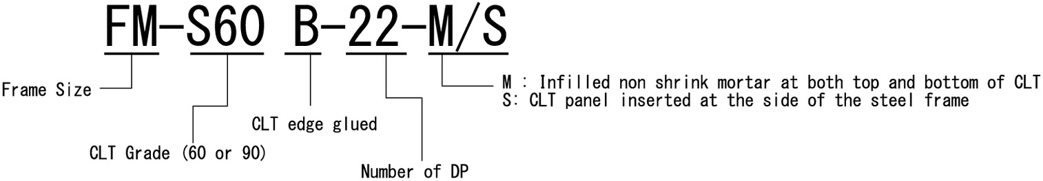
Fig. 1 shows the nomenclature for the specimens upon which testing was implemented for this paper. Fig. 2 shows an overview of the specimen tested in 2018 by Kanazawa et al. (2021) and the newly introduced four specimens in 2019.
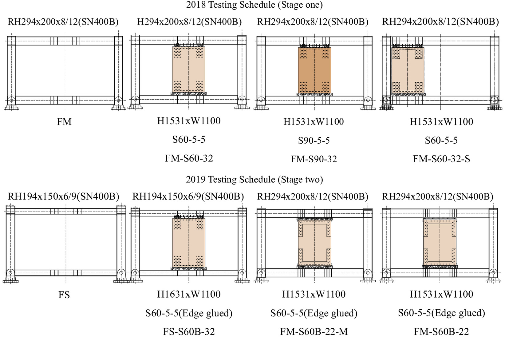
These CLT-steel hybrid frame experiments have been conducted at half scale. Furthermore, as there is no production of the preferred seven-layer CLT with half the standard thickness in Japan, five-layer CLT was used to create the test specimens.
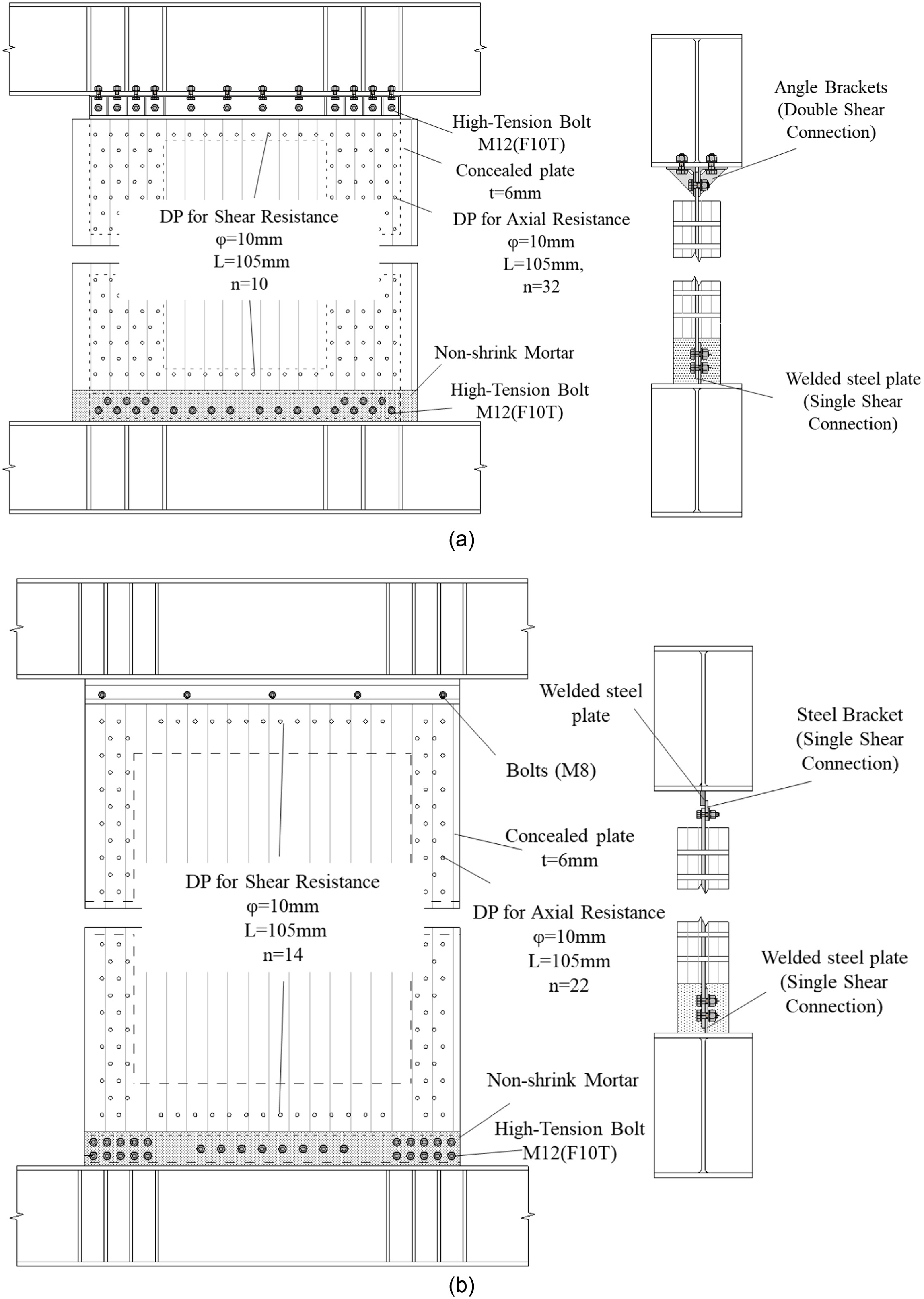
A total of four specimens were introduced for the testing schedule in 2018, including one bare frame specimen (referred to as Stage 1 specimens). The overall size of the steel frame is between the centerlines of the steel columns and the centerlines of the steel beams, respectively. Each CLT infill panel’s dimensions are 1,531 mm in height, 1,100 mm in width (1,075 mm for FM-S60-32-S), and 105 mm in thickness. The CLT panels used in 2018 did not have edge gluing. To connect the CLT to the concealed steel plate, 32 DPs were inserted in each corner to resist vertical force, 10 DPs were inserted in a line along the top of the CLT panel between the corners, and 10 more in the same fashion along the bottom, to resist shear forces. In this paper, such arrangement in the DP joint is referred to as . The length and diameter of the DPs were 105 and 12 mm, respectively. The thickness of each concealed steel plate was 6 mm. The top concealed steel plate was connected to the top steel beam using angle brackets and M12 high-tension bolts (HTBs) working in double shear. At the bottom steel beam, the concealed steel plate was also connected using M12 HTBs but to a prewelded plate working in single shear. In addition, the nonshrink mortar was also infilled to ensure fire safety and balance out the uneven surfaces of the steel beam so that the distribution of the compression load from the CLT would be even. For the details of the Stage 1 specimens, see the published paper of Kanazawa et al. (2021) in the link in the references.
In 2019, four specimens were additionally introduced (referred to as Stage 2 specimens). There were four major changes incorporated into the specimens of 2019: (1) the addition of edge gluing between the laminas in the CLT panel to increase the performance of the hybrid system as a whole; (2) the substitution of a steel frame with smaller steel beams so that the yielding of the steel beams will occur early and at small deformations to dissipate energy (applied in Specimen FS-S60B-32); (3) fewer DP connectors to ensure the yielding of DP connectors to occur before the yielding of steel beam because the performance of the DP connection was higher than expected in the Stage 1 specimens (applied in Specimens FM-S60B-22 and FM-S60B-22-M)—this can also contribute to the reduction of the workload during construction; and finally, (4) the addition of infill of nonshrink mortar (average compressive strengths 47.7 and for the 2018 and 2019 specimens, respectively) was undertaken at the top of the CLT panel to investigate the effect of a higher stiffness option for the compressive strut region of the panel (applied in Specimen FM-S60B-22-M). For specimens with a reduced number of DP connectors at the wall-to-frame connection, 22 DP connectors were inserted in each corner to resist vertical load, but an increased number of additional in-line DPs at the center to resist shear force at the top and the bottom, so that the 10 of 2018 became 14 in 2019 in each case. Since the arrangement of the DPs is different ( in 2018 and in 2019), the shape of concealed plate was redesigned. At the bottom of the lower flange of the top steel beam, a 9 mm steel plate was coaxially welded on the same axis as the CLT’s concealed steel plate. Then, the concealed steel plate was connected to the welded steel plate via a steel bracket, using M8 bolts to form a single shear connection. Table 1 provides the specimen details of the half-scale structural experiments carried out in both 2018 and 2019. Fig. 3 illustrates the layouts of the specimens with different DP configurations. The explanation of the structural design concept for the tested specimens is described in the following.
| Stage | Specimen name | Steel frame | CLT panel | Wall-to-frame connection | Frame-to-steel plate connection | Position of nonshrink mortar |
|---|---|---|---|---|---|---|
| 1 | FM-S60-32 | FM | Steel plate with DP configuration | Top: HTB (double shear) | Top: No | |
| FM-S90-32 | No edge gluing | Bottom: HTB (single shear) | Bottom: Yes | |||
| FM-S60-32-S | ||||||
| No edge gluing | ||||||
| 2 | FS-S60B-32 | FS | ||||
| FM-S60B-22-M | Edge glued | |||||
| FM-S60B-22 | FM | Edge glued | Steel plate with DP configuration | Top: M8 bolts (single shear) | Top: Yes | |
| Bottom: HTB (single shear) | Bottom: Yes | |||||
| Top: No | ||||||
| Bottom: Yes |
Structural Design Concept
The overall design of the hybrid structures created for the tests reported in this paper was based on the performance-based design approach, in which the key performance elements were the yielding and ultimate failure of the structure. It is not desirable for the CLT to fail before the yielding of the steel frame occurs because significant stiffness and strength degradation might occur if the CLT fails first. In addition, since CLT has a high structural potential, it is desired that the CLT’s innate strength be fully utilized. Therefore, the concept of the design is to allow the yielding of the steel frame to occur first and also to maximize the resistive capacity of the CLT. During the design process, the following factors are primarily considered: the types of CLT shear wall, the details of the wall-to-frame connection, and the dimensions of the steel frame.
In the first part of the design process, a parametric study was conducted on the effective strength of CLT to determine which type of CLT is the most suitable for the hybrid system. It should be noted that the sizes and dimensions of structural members are at full scale during the design process. The grade of CLT (, , S60, or S90), layer configuration (5 or 7 layers), width (1,200, 1,800, or 2,400 mm), and height (3,000 or 4,000 mm) were set as parameters. and refer to the average Young’s modulus (equal to 6 and 9 GPa, respectively) of the outer layer laminas used in the CLT in the major direction, combined with laminas that have lower average Young’s modulus (equal to 3 and 6 GPa, respectively) in the inner layer; whereas S60 and S90 refer to CLT in which all the laminas have the same Young’s modulus (equal to 6 and 9 GPa, respectively). The thickness of each lamina was 30 mm. The ultimate loading capacity was determined by the minimum of the ultimate shear capacity and the ultimate bending capacity , using Eqs. (1)–(3)where ; , , and = width, height, and thickness of the CLT panel, respectively; = in-plane standard shear strength (equal to ); and = in-plane standard bending strength of CLT (equal to for S60 and for S90). The standard strength values of the CLT panel can be found in the CLT Construction Manual (Committee of CLT Manual 2016). Since the most common timber species in Japan is the Japanese Sugi and CLT made from it is usually S60 graded, the S60 grade was adopted for use in the experiment as the test standard. However, as a result of the aforementioned calculation, the CLT panel graded S90 with seven layers was found to have the highest value. A substantial difference (largest at 194.4 kN) in value was also found when compared to S60 with the same configuration. Therefore, S90 grade CLT was adopted for use in the experiment also, for tests undertaken with the aim of increasing the lateral load capacity.
(1)
(2)
(3)
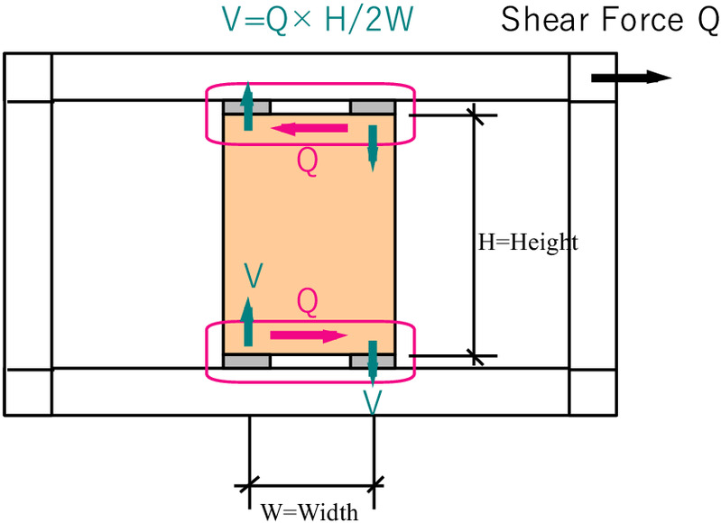
In the second part of the design process, the appropriate number of DPs that should be used in the hybrid system was determined when considering the wall-to-frame connection. Failure at the wall-to-frame connections should be avoided before any failure occurs in the CLT panel to maximize the utilization of the shear capacity of the CLT. Therefore, the number of DPs was decided by designing the strength of the connection to be higher than the strength of the CLT panel (i.e., , in which the vertical force exerted at the bottom of the CLT is calculated using Eq. (4), which is defined according to Fig. 4
(4)
There were two cases considered for the strength of the DP connections, in which the wood and DPs were first to fail, respectively. According to the Architectural Institute of Japan (AIJ) Standard (AIJ 2006), the design equation for calculating the shear strength of the DP connectors , assuming the DPs will reach the ultimate limit state before the wood, is given as Eq. (5)where = reduction factor for a certain number of DPs in a row (equal to 0.9 in this case); = number of DPs in a row; = yield shear strength of a single DP; and = ultimate strength ratio of the DP connectors (equal to 1.0).
(5)
On the other hand, the design equation for calculating the shear strength of the DP connectors , in the case in which the wood will fail before the DPs, is given as Eq. (6). This equation is defined in Eurocode 5 (BSI 2014)where = net cross-sectional area perpendicular to the grain; = net shear area parallel to the grain direction; = characteristic tensile strength of the timber member; and = characteristic shear strength of the timber member. As a result of the comparison, it was concluded that at least 32 DP connectors were required at each corner. As for the 22 DP connectors in Stage 2 specimens, it was decided to use the lower limit strength value (equal to 249.58 kN) obtained from the tensile element test of 32 DP connectors. Since the vertical force is 162.96 kN, the strength of 21 DP connectors (equal to ) was enough to fulfill the design requirement. However, considering the arrangements of the DP connectors, it was decided that it was better to insert the DPs in pairs. Therefore, it was concluded that 22 DPs should be inserted.
(6)
The next part of the design process was calculating the steel frame dimensions during the design of the full scale intended steel structure into which the hybrid wall was placed. The intended steel structure is a 7-story office building with 7.2 m length and 4.0 m height wall module. The steel frame dimensions were further verified by satisfying Eqs. (7) and (8). These calculations were done to ensure the CLT could be fully utilized, while allowing the steel to yield first before the CLT ultimately failedwhere = moment exerted from the CLT to the steel beam (equal to ), = design steel yield strength (equal to ); and and = elastic section modulus and the plastic section modulus, respectively. Table 2 provides all the material properties of the steel columns and beams.
(7)
(8)
| Grade | Stage 1 specimen | Stage 2 specimen | |||
|---|---|---|---|---|---|
| Column | FM beam | Column | FM beam | FS beam | |
| SN490B | SN400B | SN490B | SN400B | SN400B | |
| (mm) | |||||
| Design bending force, () | 350 | 282 | 354.06 | 266.24 | 266.24 |
| Design shear force, () | 202.1 | 162.8 | 223.37 | 186.42 | 186.42 |
| Cross-sectional area, () | 118.5 | 71.05 | 118.5 | 71.05 | 38.11 |
| Shear force resisting surface area, () | 27 | 21.6 | 27 | 21.6 | 10.56 |
| Second moment of inertia, () | 20,200 | 11,100 | 20,200 | 11,100 | 2,630 |
| Section modulus, () | 1,350 | 756 | 1,350 | 756 | 271 |
| Plastic section modulus, () | 1,480 | 842 | 1,480 | 842 | 301 |
| Ultimate bending force, () | 518 | 237.4 | 524 | 224.11 | 80.12 |
| Ultimate shear force, (kN) | 545.6 | 351.7 | 603.1 | 402.67 | 196.86 |
| Elastic modulus (MPa) | 205,000 | ||||
| Shear modulus (GPa) | 79,000 | ||||
Loading Protocol and Instrumentation
In this section, the loading protocol and instrumentation will be described for the Stage 2 specimens. It is noteworthy that while the loading protocols applied for Stage 1 and 2 specimens were slightly different, the results obtained for both stages were essentially the same. The loading procedure for Stage 2 specimens is illustrated in Fig. 5. The test specimens were subjected to a cyclic loading protocol of controlled angular displacement with cycles grouped in phases at , , , and . The first phase for contained only two full reversed cycles, and the others contained three cycles. After that, the loading continued until , the target angular displacement by which the specimen should have failed.
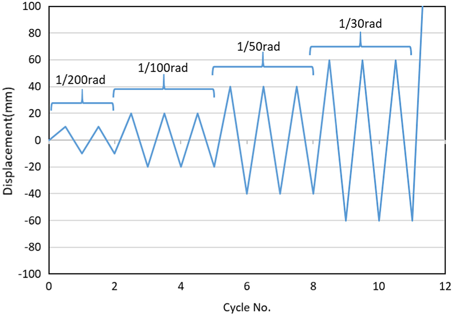
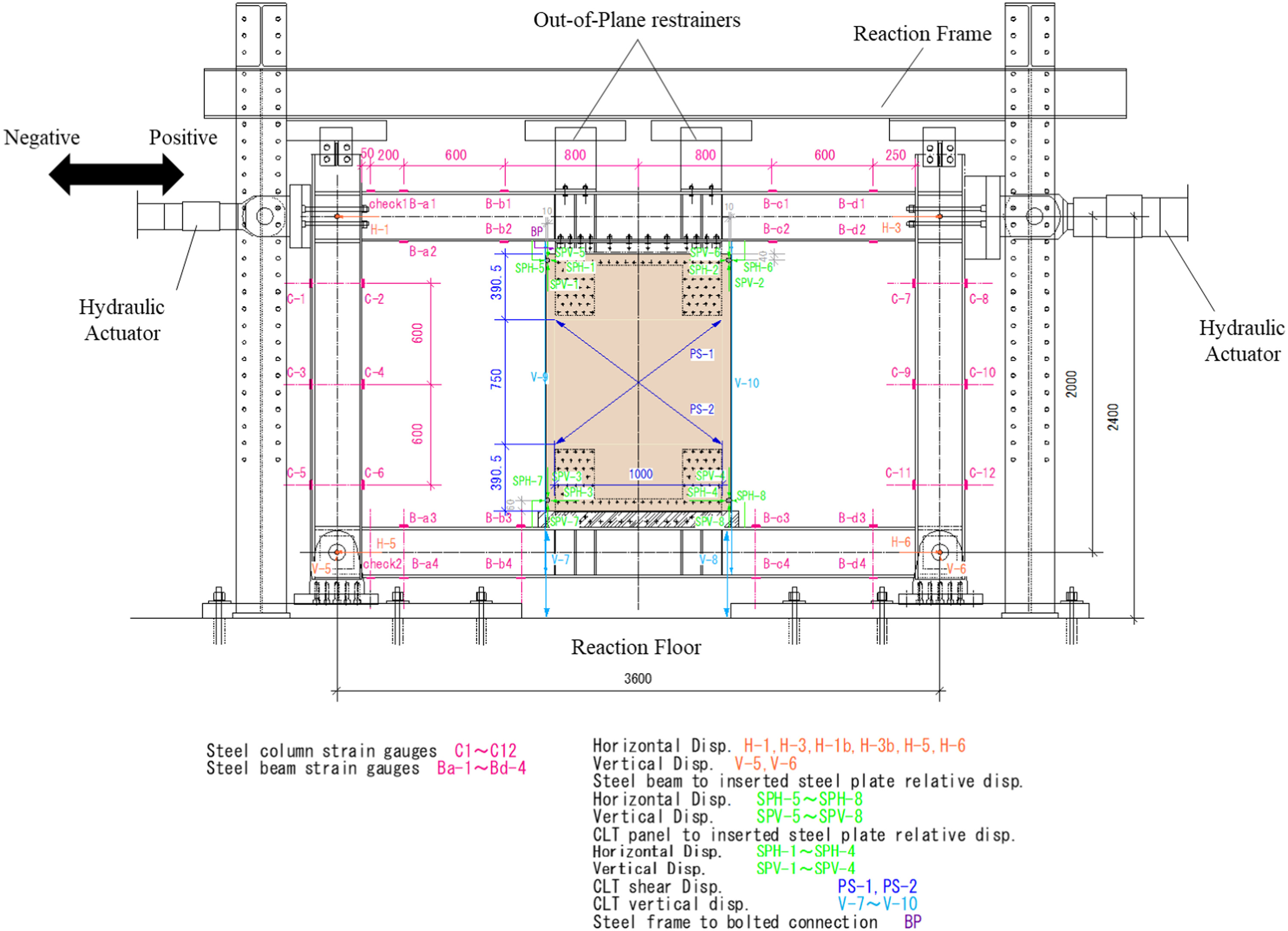
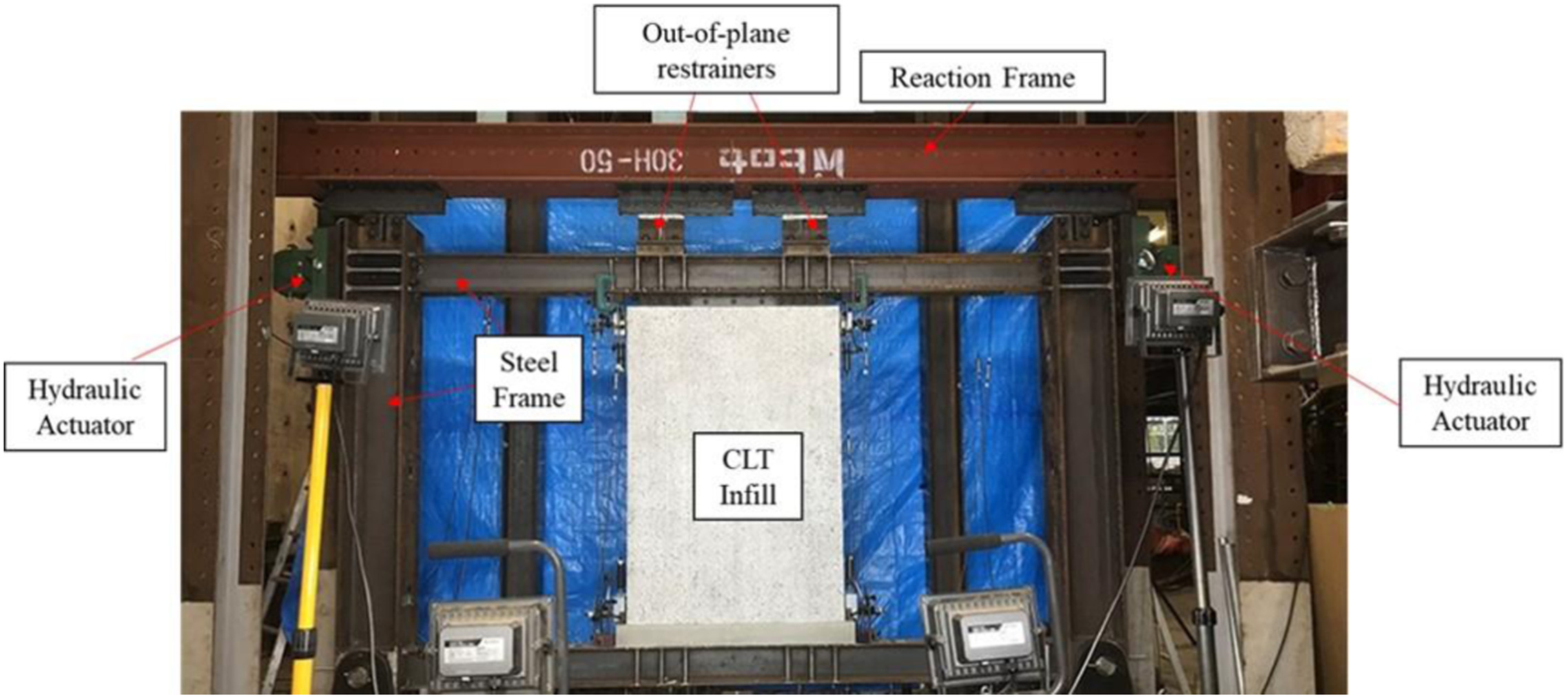
Fig. 6 shows the diagram of the testing instruments and measuring positions. Two hydraulic actuators exerted lateral force on the test specimen from both sides of the frame. A hydraulic actuator on one side was fixed to the reaction wall, and another was fixed to a steel tower on the other side. Two out-of-plane restrainers were set above the specimen’s top beam to prevent out-of-plane deformation. The columns of the steel frame were fixed to the reaction floor. Fig. 7 provides the example photo of Specimen FS-S60B-32 for better understanding of the experiment.
Shear Resistance of CLT and Steel Frame
The following calculation method was used to acquire the shear force in the steel frame and the infilled CLT shear wall. The shear force resisted by the steel frame () can be determined by adding the shear forces in the left column () and in the right column (). The strain gauges C-1, C-2, C-5–C-8, C-11, and C-12, placed at the 1,200 mm height of the steel columns, were used to calculate and . Eq. (9) shows the method of calculating the shear force in each column. It should be noted that the steel columns were to remain elastic throughout the experiments, which was suitable for the evaluation of the shear resistance in the steel columnswhere and = bending moments of the top part and bottom part of each steel column, respectively; and and = strain values recorded using strain gauges located at the top (C-1, C-2, C-7, and C-8) and bottom (C-5, C-6, C-11, and C-12) of the steel columns, respectively [it should be noted that and are averaged values from the readings of strain gauges on both sides (i.e., compression and tension)]; = elastic modulus of steel (); = section modulus of the steel columns (); and = vertical distance between the strain gauges (1,200 mm).
(9)
In the CLT-steel hybrid wall system, the total shear force () was resisted by two components, the steel frame and the CLT shear wall. Therefore, from the load sharing by the two components, can be acquired by using Eq. (11)
(10)
(11)
Test Results and Discussions
Failure Mechanisms and Load-Displacement Properties
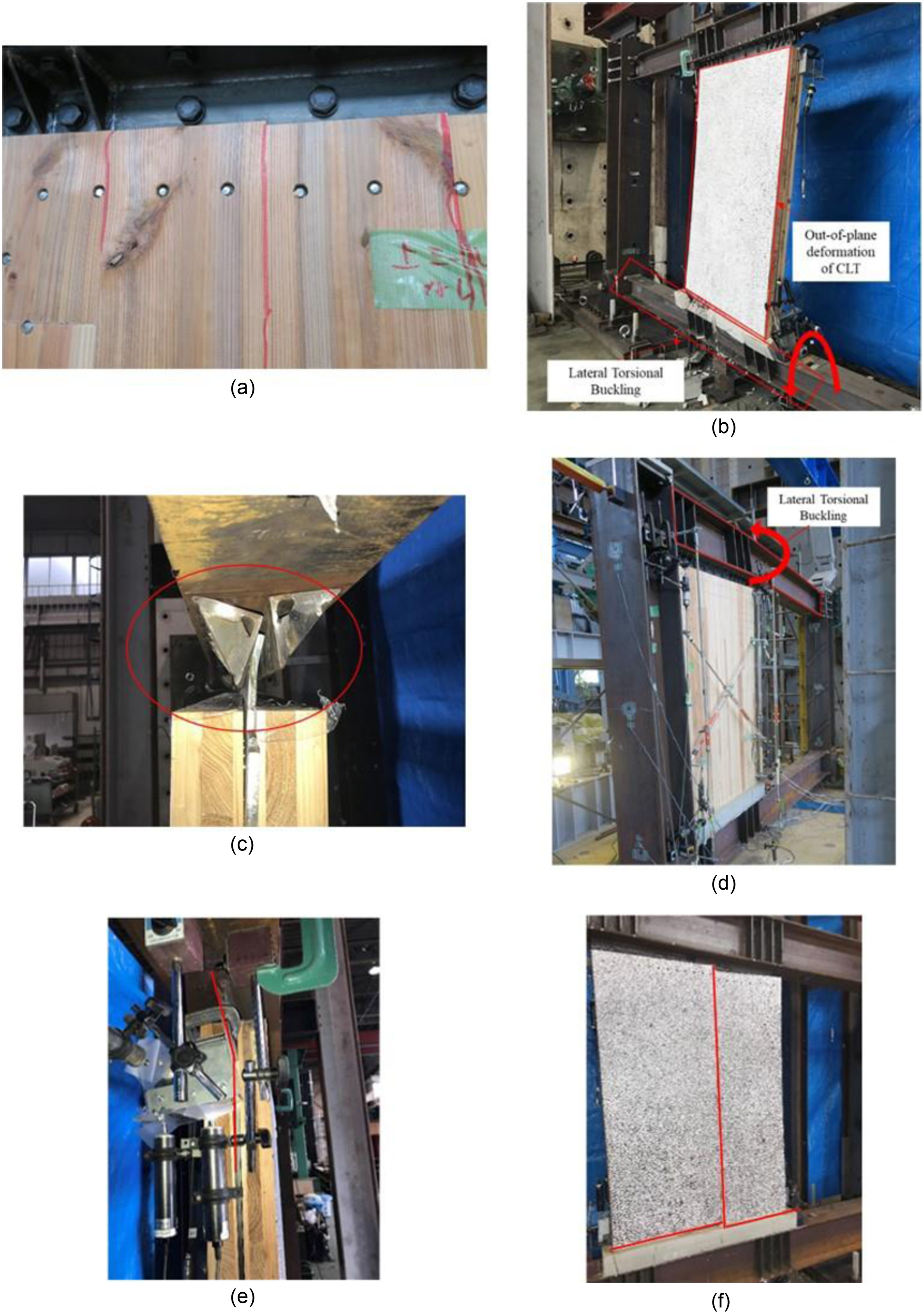
Fig. 17 (in “Numerical Verification” section) summarizes the comparison between the test hysteresis result and numerical hysteresis results, together with the plotting of the yielding of steel beam, shear failure in the CLT infill, and yielding of DP shown. From the figure, it can be observed that the yielding of steel beam occurred at around in all specimens. As for the shear failure of CLT, with the exception of FM-S60-32-S, the CLT-infilled specimens with FM beams experienced strength degradation at an angular deformation of around due to the shear failure of the CLT infill, as shown in Fig. 8(a). It can be said that the shear capacity of the CLT infill was fully utilized. As for FS-S60B-32, strength degradation did not occur because there was no shear failure in the CLT infill, due to the lateral torsional buckling of one of the two steel beams markedly at [Fig. 8(b)] and also the shear failure of HTB at the wall-to-frame connection at the final cycle [Fig. 8(c)]. It should be noted that all specimens were tested successfully, per the loading schedule, except for Specimen FM-S60-32-S, in which test had to be terminated prematurely because of the significant lateral torsional buckling of the beam during the negative direction of the first cycle of [Fig. 8(d)], after which the shear failure of CLT followed almost immediately. Concerning the yielding of DP, the DP in specimens with configuration yielded at similar displacement of , except Specimen FS-S60B-32. In Specimen FS-S60B-32, the DP yielded at because there is less effectiveness in the load transmission from the beam to the wall-to-frame connection, due to the more slender beams. On the other hand, the DP in specimens with configuration were observed to undergo early yielding and failure at the wall-to-frame connection, of a type that involved compressive buckling at the concealed steel plate [Fig. 8(e)] at a relatively smaller displacement at due to the lesser number of DP, as can be observed from the plotting for Specimen FM-S60B-32. However, for Specimen FM-S60B-22-M, the DP yielded at because of the confinements from the infilled nonshrink mortar at top and bottom of the CLT panel, where the CLT panel was unable to deform freely. Because of the early yielding of the DP connectors, both specimens showed particularly significant failure in the CLT shear wall, which split in half vertically in the middle, as shown in Fig. 8(f). Table 3 provides the summary of the failure mechanisms during the experiments. Generally, almost no slip behavior was observed among the hysteretic behavior of the specimens with CLT infill, an outcome that was similar to the hysteretic behavior of the steel frame specimens. This showed that the steel frame was dominant in terms of the behavior of the hybrid system.
| Specimen name | Failure mechanisms | |||
|---|---|---|---|---|
| Steel frame | Nonshrink mortar | Wall-to-frame connection | CLT infill | |
| FM | Beam yielding () | Cracking () | — | — |
| FS | Beam yielding () | Cracking () | — | — |
| FM-S60-32 | Beam yielding () | Cracking () | Tensile failure of steel plate () | Shear failure () |
| FM-S90-32 | Beam yielding () | Cracking () | Buckling of concealed steel plate () | Shear failure () |
| FM-S60-32-S | Beam yielding () | Cracking () | Pull out failure of grouped drift pins () | Shear failure () |
| Beam buckling () | Cracking () | |||
| FS-S60B-32 | Beam yielding () | Cracking () | Shear failure of high-tension bolts () | — |
| Beam buckling () | Cracking () | |||
| FM-S60B-22-M | Beam yielding () | Cracking () | Buckling of concealed steel plate () | Shear failure () |
| FM-S60B-22 | Beam yielding () | Cracking () | Buckling of concealed steel plate () | Shear failure () |
Load Sharing Effect between the CLT Panel and the Steel Frame
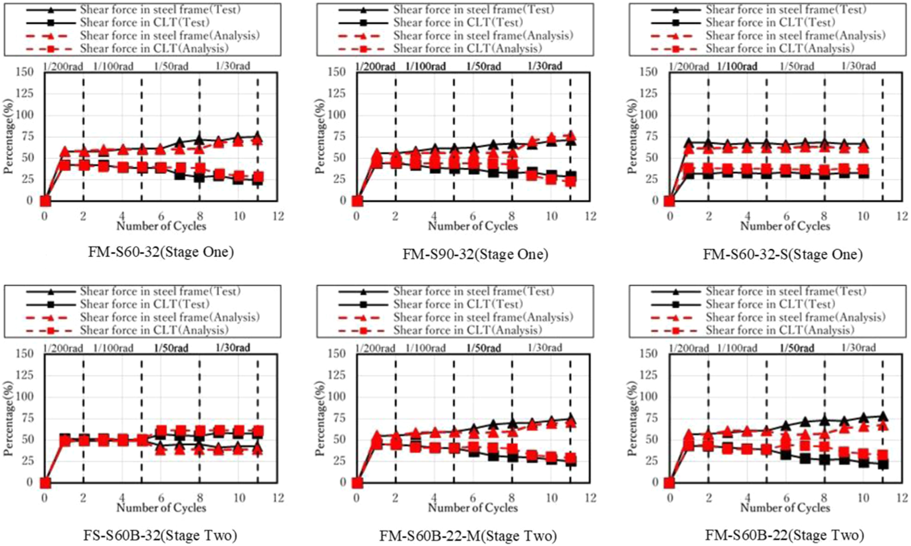
Fig. 18 (in “Numerical Verification” section) shows comparison of the load sharing effect between the test and numerical results. As described previously, in the CLT-steel hybrid system, the shear force is jointly resisted by the CLT panel and the columns of the steel frame. In order to evaluate the effectiveness of the hybrid system’s lateral load resistance, the percentage of shear force resisted by each of the subsystems was calculated for all specimens using the values of Eqs. (10) and (11). From the figure, it can be seen that in FS-S60B-32, the CLT infill resisted more than half of the shear force until the end of the experiment. That was because, as compared with the tests based on the FM frame, this specimen used the more slender FS beams, which ultimately failed in this case by an out-of-plane buckling deformation at 1/30 rad without the CLT shear wall having shear failure, after which the experiment was terminated. As for the specimens in which FM beams were applied, the steel frame resisted more than 50% of the shear force throughout the experiment because of the more robust beams, which were more capable of transferring the lateral loads to the steel columns. At around , the percentage of force resisted by the CLT infill started to decrease gradually due to the accumulation of damage, except Specimen FM-S60-32-S. This was because in this specimen in which the CLT infill is positioned at the side instead of in the center of the steel frame, the shear properties of CLT infill was not effectively taken advantage of at small displacements. This led to the CLT infill having adequate shear capacity for resisting shear load until large deformation (i.e., ), after which it only started to show signs of shear failure.
Numerical Verification
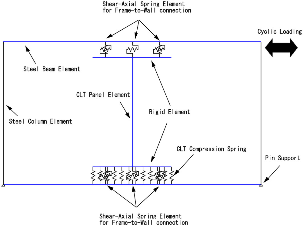
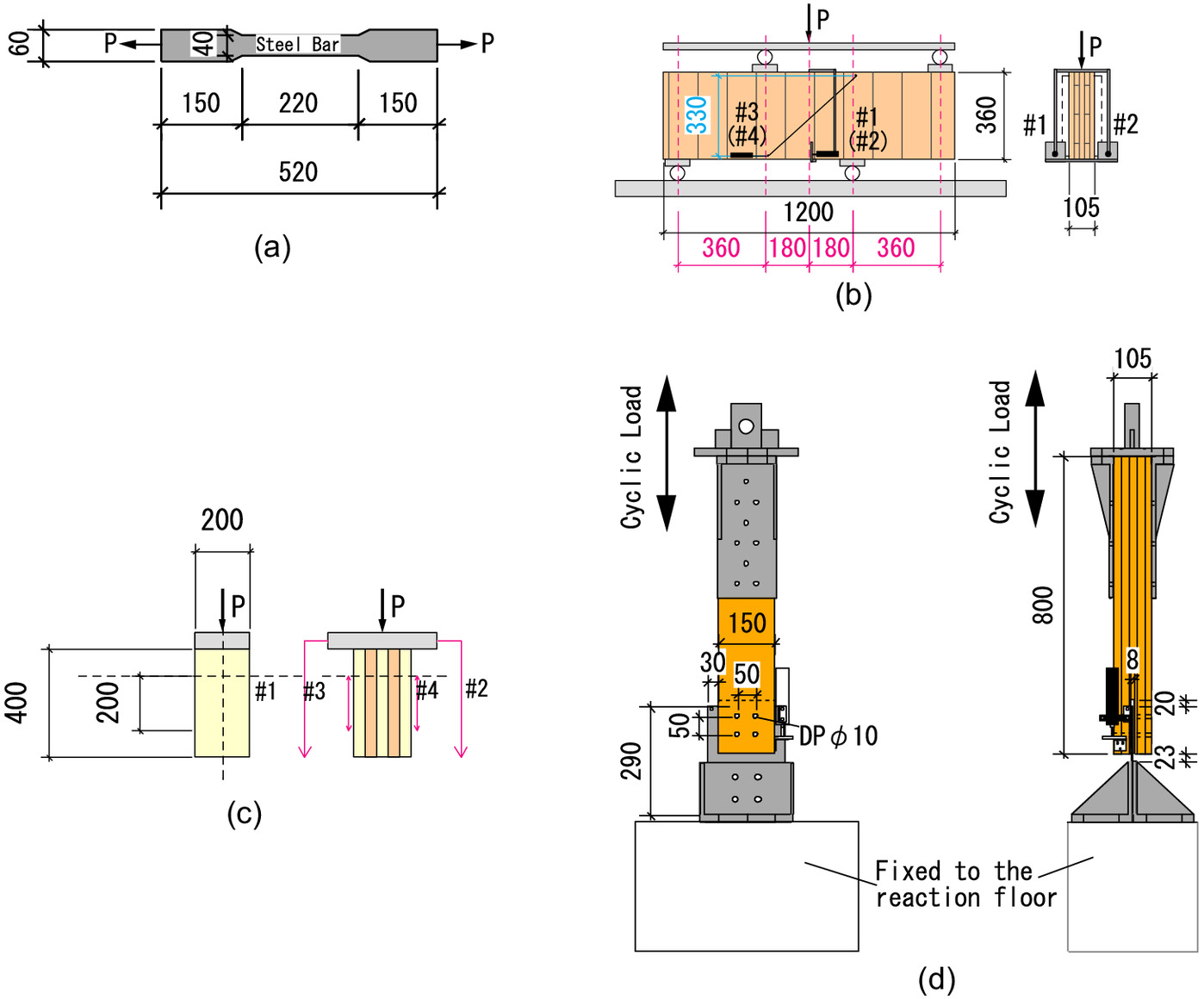
To better understand a structure’s seismic performance, a hysteresis model that can accurately reflect its stiffness and strength degradation, performance under large deformations, and energy dissipation capability is required. In this paper, a two-dimensional (2D) nonlinear finite-element analysis model was constructed to recreate the hysteretic properties of the CLT-steel hybrid system using commercial software, SNAP V7.0. The model comprised three components: the steel frame, CLT infill panel, and DP connections. The model for Specimen FM-S60-32 is shown in Fig. 9 as an example, of which the essential features apply to the model in general. Fig. 10 provides an overview of a series of elemental tests conducted to help define key parameters of the model. The CLT specimens used for the elemental tests were cut out from the same large CLT panels as the hybrid system experiments to ensure that confounding strength variations of the timber were kept to a minimum. The details of each elemental test will be included as their respective section of the model is described.
Modeling of the Steel Frame
The hysteretic response of each of the steel member (e.g., beams or columns) was reproduced using the modified Ramberg-Osgood model proposed by Meng et al. (1992). The force ()-displacement () relationship that defines the hysteretic loop of the model is given in Eq. (12)where and = both the unloading force and displacement; = unloading stiffness at ; and = parameter used to define the curvature of the hysteresis loop for calibration purposes. The coefficient defines the unloading path of the loop targeting for point and is given in Eq. (13)where = target point that the unloading path will arrive at. This target point can be shifted along the horizontal axis by multiplying by parameter , when the unloading point occurs after the yielding point . When , the stiffness of the unloading path will be less than the initial stiffness which enables consideration of the strain-softening phenomenon to take place.
(12)
(13)
A model of the bare steel frame whose sectional behavior follows the previously mentioned modified Ramberg-Osgood equations was developed for calibration to fit the cyclic experiment results of the bare steel frame. The steel bare frame model is conceptually the same as the example shown in Fig. 9, minus the CLT infill elements. The steel frame’s columns and beams were modeled using software-defined column elements and beam elements, which can resist bending, shear, and axial forces. The elastic and yield values used for these elements are defined using a previously conducted steel bar tensile element test, illustrated in Fig. 10(a). The bending strength can be obtained directly from the test, while the shear strength was obtained by dividing the test result by . and were used to calculate the ultimate moment force and ultimate shear force , respectively, forces that defined the yield properties of the steel frames in the model. The values obtained for and for the FM steel beams were around 2.8 times and 2 times larger than the FS steel beams, respectively. The material properties of the steel are provided in Table 2.
Pin supports were inserted at the bottom of the steel frame to allow flexibility in rotation while constraining the vertical and horizontal displacements. In order not to overevaluate the rigidity at the ends of each steel member, the steel column-to-beam panel zone was not set to be rigid. Previous literature has already reported that steel frame might show semirigid behavior at the welded column to frame connection (Vertes and Ivanyi 2004). The postyield behavior was based on the formation of plastic hinges, which were set to occur outside the panel zone of the steel column and beam connections.
During the calibration process, the parameters and were changed accordingly through trial and error. The definable range in the analysis software for and are 1–20 and 0–1, respectively. Therefore, increment steps of 1 and 0.1 in changing the values of and was conducted until the numerical result fit the experiment result. As the result of the calibration process, the hysteresis loop parameters, and were derived. Similar parameter values have also been reported in earlier literature (Ohi et al. 1992), which corroborates the values’ validity. A good agreement between the experimental and analytical results can also be seen in Fig. 11.
Modeling of the CLT Shear Wall Infill
The infilled CLT shear wall was modeled as an I shape with a vertical beam element in the middle and horizontal beam elements on the top and at the bottom, and which is defined to have the same dimensions as CLT shear wall in the experiment. In most of the previous literature concerning CLT-hybrid structures, the CLT infill shear wall is defined as an elastic element. However, several CLT panels experienced severe shear failure during the experiments because the utilization of the CLT’s shear capacity was maximized. Therefore, the vertical beam element is defined as nonlinear to reproduce the nonlinear strength and stiffness degradation of the CLT panel near its point of ultimate failure in shear. Fig. 12(a) shows the stress–strain curve obtained from the shear element test and the model for specimens infilled with S60 grade CLT. The shear strain was obtained from the diagonal LVDTs [#3 and #4 in Fig. 10(b)] by Eq. (14) with reference to Fig. 12(b)
(14)
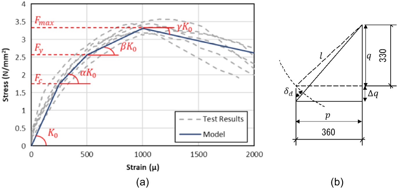
As shown in Fig. 12(a), much as with the failure mechanism observed during the experiments on the hybrid test specimens, there was no sudden strength degradation during the CLT shear element test. The backbone parameters for the 4-linear stiffness degradation model shown in Fig. 13 were decided by tracing the averages of the test results. The reason for adopting the 4-linear stiffness degradation model is that this model is one of the very few models incorporated within the SNAP analysis software that allows for strength degradation modeling. Second, this model is relatively easy to define because it does not require many parameters, which may also facilitate a simpler design for such a hybrid structure. Negative values can be inputted for the stiffness ratio and , so that the path of the hysteresis loop can be adjusted according to the displacement at which the strength degradation occurs. The CLT material properties used for the beam element (Table 4), except the elastic modulus obtained from CLT compression test [Fig. 10(c)], were obtained from the previously conducted CLT shear element test illustrated in Fig. 10(b).
| Material properties of CLT | 2018 specimen | 2018 specimen | 2019 specimen |
|---|---|---|---|
| CLT grade | S60 | S90 | S60 (with edge glue) |
| Elastic modulus, (MPa) | 5,601 | 7,034 | 3,513 |
| Shear modulus, (MPa) | 626.9 | 798.0 | 974.3 |
| Compression strength, () | 25.33 | 29.14 | 22.82 |
| Shear strength, () | 3.38 | 4.08 | 4.21 |
The horizontal beam elements, located at the top and bottom of the CLT beam element, were defined as rigid to allow effective load transfer between the CLT and the steel frame through the DP connections in the numerical model.
As for the compressive resistance incurred at the contact surface between the CLT panel and the nonshrink mortar, it was modeled using spring-bearing elements placed 100 mm apart. In order to reproduce the uplifting deformation of the CLT, the bearing springs were adjusted to resist only compression. Each of the bearing springs was modeled as an elastic-plastic element, and the parameter input was obtained from the CLT elemental test in compression, illustrated in Fig. 10(c), which yielded the Young’s modulus and compression strength for the CLT. It should be noted that was obtained using the local strain-measurement LVDTs (#3 and #4). Eqs. (15) and (16) were used for the calculation of the stiffness and the yield strength properties for the bearing spring elements. In the analysis model, each of the bearing springs is assumed to bear the compression load partially by a certain compression area. The compression springs at the ends were considered to only have half the stiffness and yield strength. The input values are provided in Table 5where = thickness of the CLT (105 mm); = distance between the bearing springs (100 mm); and = compression strength of the CLT. Ec/290 () is an equation for calculating the bearing stiffness of the CLT, proposed by Fukumoto et al. (2021). This equation was defined focusing on the compressive stress transfer from the CLT panel to the steel beam. It also takes into account of the curvature deformation of the steel beam under compression by the infill.
(15)
(16)
| Material properties | 2018 specimen | 2018 specimen | 2019 specimen |
|---|---|---|---|
| CLT grade | S60 | S90 | S60 (with edge glue) |
| Compression Young’s modulus, (MPa) | 5,601 | 7,034 | 3,513 |
| Compression strength, () | 25.33 | 29.14 | 22.82 |
| Compression stiffness, () | 202.8 | 254.68 | 127.19 |
| Compression yield strength, () | 265.9 | 305.9 | 239.6 |
Modeling of Frame-to-Wall Connection (Drift Pin Connections)
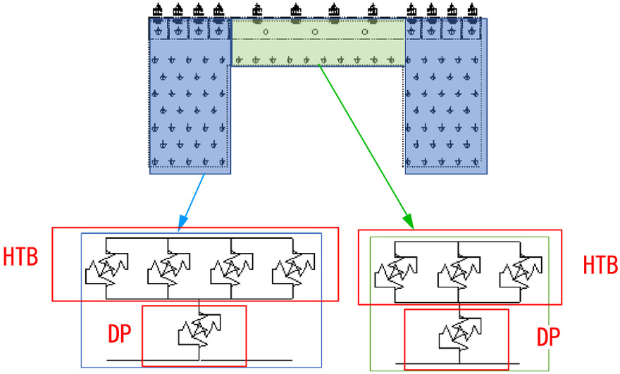
The overall frame-to-wall connection is the key component that ensures the two subsystems (CLT infill and steel frame) work well together to resist lateral loads in a steel-timber hybrid structure (Li et al. 2015). Modeling of this overall connection must be carefully conducted if a satisfactory result is to be obtained from the analysis. Under lateral loading, the DPs group located at the four corners of the panel may experience rotation. Due to the rotation, it may induce each DP to move at different direction and such behavior should be accounted in the model. However, from calculations of the angle deformation of the infill using the recordings of LVDTs (SPH-1–4) at the corners of the infill (refer to Fig. 6), the results showed that the infill was only subjected to less than 1° of angle deformation. Furthermore, it has been reported in previous literature that the resisting directions of the DPs in the CLT panel do not have much effect on the capacity and stiffness of the connection at least for the case of fewer number of DPs in a row, even when the DPs are in different arrangements (Nakashima et al. 2016). With the aforementioned reasoning, it was considered that the rotation behavior of the DP groups be eliminated from the analysis model, since the rotation effect is insignificant. On the other hand, during the tests, the LVDTs generally recorded only small (effectively negligible) displacements between the steel frame and the bolted connections, except for Specimen FS-S60B-32, whose ultimate failure mode of beam buckling included shear failure at the bolt connection [refer to Fig. 8(c)]. In the other specimens, no severe damage was observed at the bolted connections. Therefore, the bolted connections were considered rigid, and only the DP connection was considered when modeling the frame-to-wall connection. However, for Specimen FS-S60B-32, the stiffness of the connection was reduced by modeling the bolted and DP connections as series spring connections, in the manner shown in Fig. 14. The equation for the calculation of the stiffness in that case is given in Eq. (17)where and = stiffness of the HTBs and DPs, respectively; and was obtained from the DP cyclic elemental test, which will be describe subsequently. On the other hand, was obtained using Eq. (18)where = design shear force of an F10T HTB as stated in the AIJ Standard (AIJ 2019) (equal to 33.9 kN); = number of surfaces for shear force transmission; = number of bolts in the connection; and = displacement suggested by Shi et al. (2011). In the case of the bolt shear failure mode, which was a feature of the observed failure mode in the experiment performed on Specimen FS-S60B-32, was proposed to be 1.35 mm.
(17)
(18)
The connections of CLT panels to the steel frames were modeled using a series of axial-shear spring elements, which also have tensile and compression resisting capabilities.
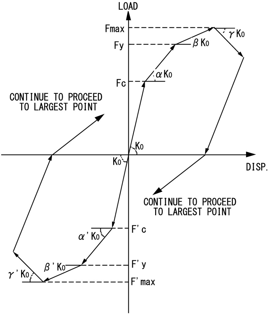
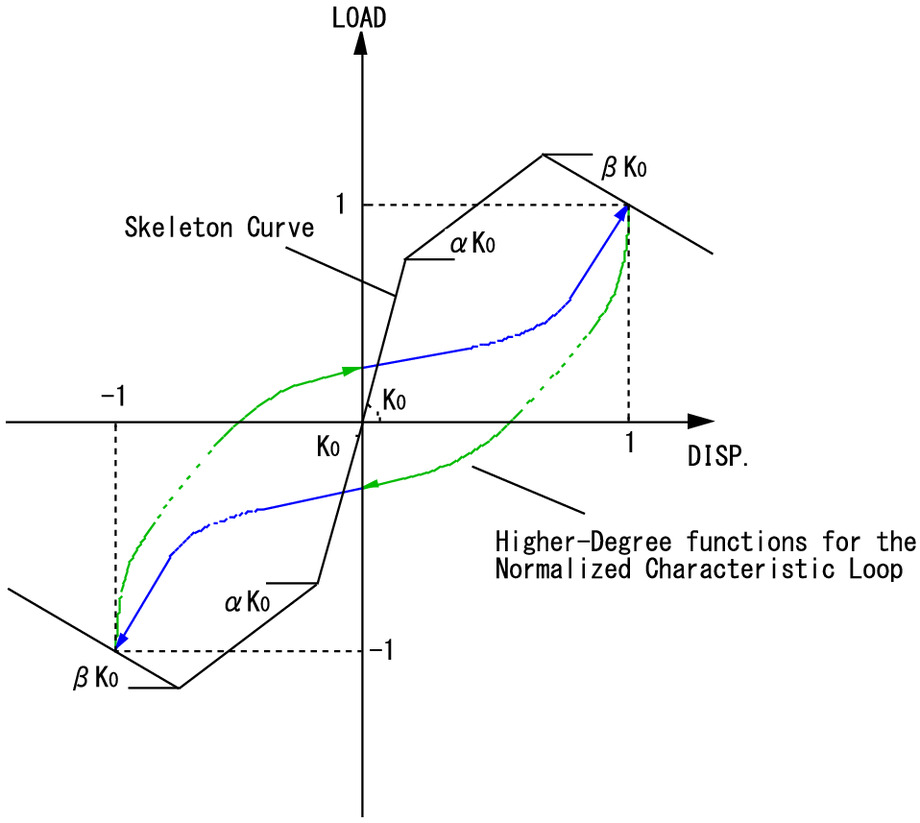
The axial-shear spring elements were represented using the modified normal characteristic loop (NCL) model for wooden structures (Fig. 15), as proposed by Matsunaga et al. (2008). The original NCL model consists of a skeleton curve and a normalized characteristic loop, which can trace the slip effect, enlarging hysteresis loop area phenomenon, and stiffness degradation, which are all observed in the hysteretic behavior of RC structures. Here, the modified NCL model takes advantage of these capabilities to similar model behaviors, which can be observed in the wooden structure, while also being able to capture the complexity of varying slip lengths in the hysteresis curve obtained from the wooden shear wall tests by introducing a new exponent parameter in the characteristic loop function given in Eq. (19)where = loop area coefficient; and = slip pattern coefficient. The exponent serves to adjust the slip length of the NCL, where two different values of , for example and , are required to define the loading curve (curve showing load increment ) and unloading curve (curve showing load decrement) in each direction of the loop, as shown in Fig. 15.
(19)
Cyclic loading tests were conducted to obtain the load-deformation relationships for the frame-to-wall connection. The test setup is illustrated in Fig. 10(d). The values from the test results given in Table 6 were used to calibrate the model parameters, and the calibration results for the NCL model are listed in Table 7. It should be noted that the calibration was conducted accordingly to a specific modeling procedure proposed by Matsunaga et al. (2008). In order to define the yield strength and stiffness ratios for the backbone curve of the model, the strength properties and stiffness were adjusted by a ratio obtained by dividing the number of DPs used in the timber-steel hybrid systems by the number of the DPs in the cyclic test setup. Fig. 16 compares the connection test results and the modified NCL model as calibrated. It can be seen from the comparison that the analysis result can accurately reproduce the observed slip and pinching behavior of the DP connection under its cyclic experimental test loading.
| Material properties | 2018 specimen | 2018 specimen | 2019 specimen | 2019 specimen |
|---|---|---|---|---|
| Number of DP | 32 (axial) | 10 (shear) | 22 (axial) | 14 (shear) |
| Yield strength of DP, (kN) | 369.49 | 115.47 | 254.03 | 161.65 |
| Stiffness of DP, () | 238.23 | 74.45 | 163.78 | 104.23 |
| Drift pin connection parameters | Values |
|---|---|
| Loop area coefficient, | 0.313 |
| Slip pattern coefficient, | 0.880 |
| Minimum exponent, | 4 |
| Maximum exponent, | 20 |
Modeling Results
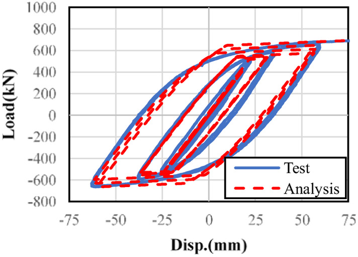
The numerical model was subjected to the same loading protocol as the structural experiment. The model’s predictions of hysteresis loops, shear force sharing effect, and the cumulative energy dissipation of the hybrid systems were compared with the test results in this section, with outcomes shown in Figs. 17–19.
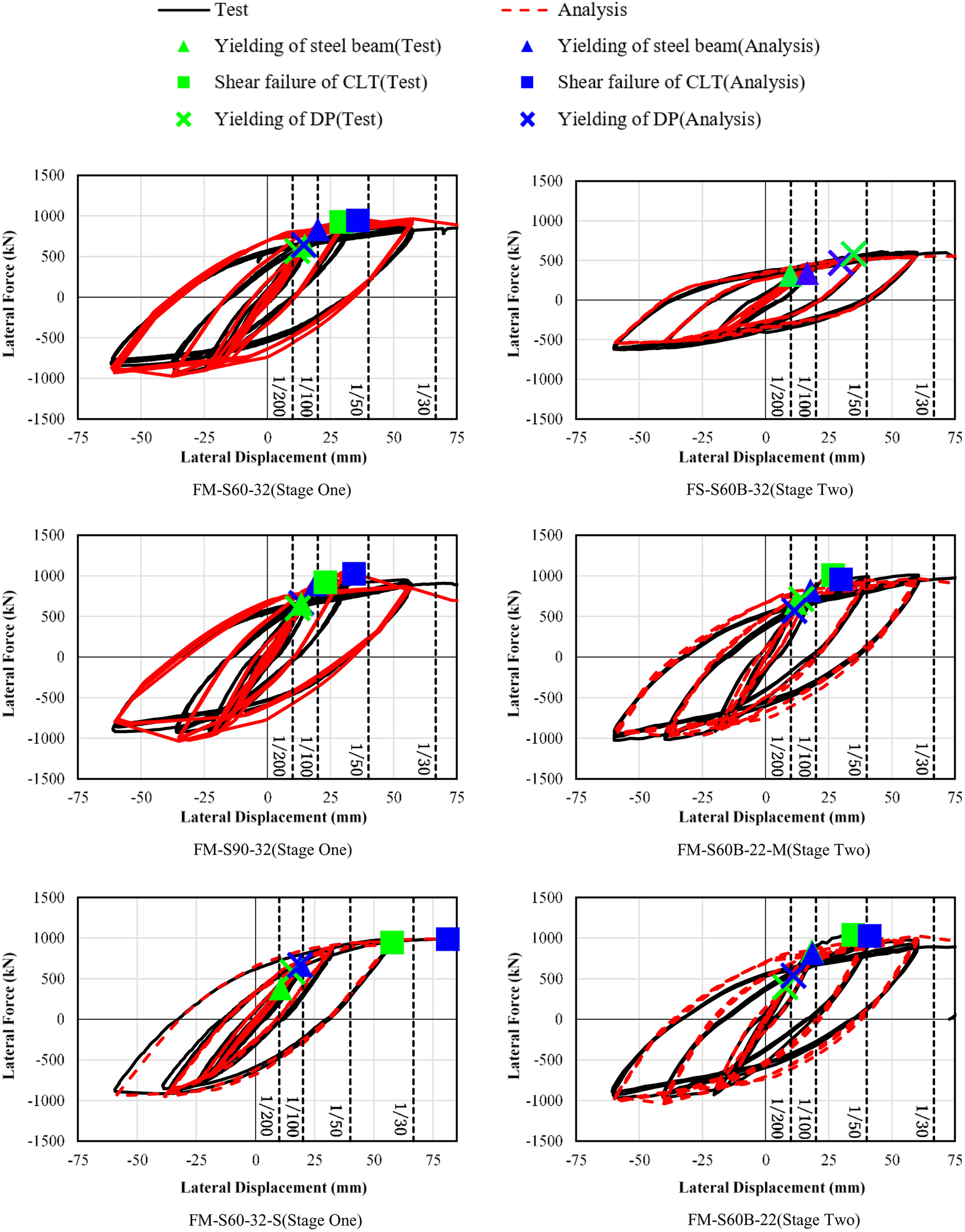
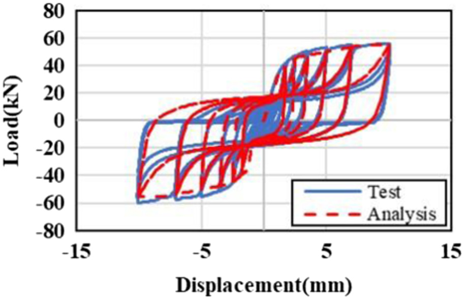
From Fig. 17, it can be observed that the plotting of the yielding of steel beam and shear failure of CLT from the test and numerical results are in good agreement. As mentioned in the section “Test Results and Discussions,” the test had to be terminated prematurely for Specimen FM-S60-32-S, due to the significant lateral torsional buckling of the beam. This explains the reason why the shear failure of CLT in the model occurred later than in the experiment for this particular specimen, because lateral torsional buckling was not considered in the numerical model. As for the yielding of DP, the DP in specimens with fewer number of DP tend to yield at relatively smaller angular displacements. The analysis model is also able to simulate such behavior and the occurrence of the yielding of DP in the experiment and analysis show good agreement, as shown in the figure. Moreover, the hysteretic behavior of the hybrid walls was similar to that of the steel bare frame, indicating that the steel frame governs the behavior of the hybrid system. The numerical results were also able to reproduce such behavior of the hybrid system.
From Fig. 18, it can be seen that the CLT infill resisted more than half of the shear force in Specimen FS-S60B-32, as described previously. As for the specimens with the more robust beams, different results were observed, in which the steel frame resisted more shear force than the CLT infill. However, when the hybrid system started to show signs of failure as the displacement increases, the prediction accuracy of the model starts to drop by a little, due to the slight difference in the timing when the failures occurred. Nonetheless, the model predictions were capable of capturing the trend of the load sharing effect between the two subsystems.
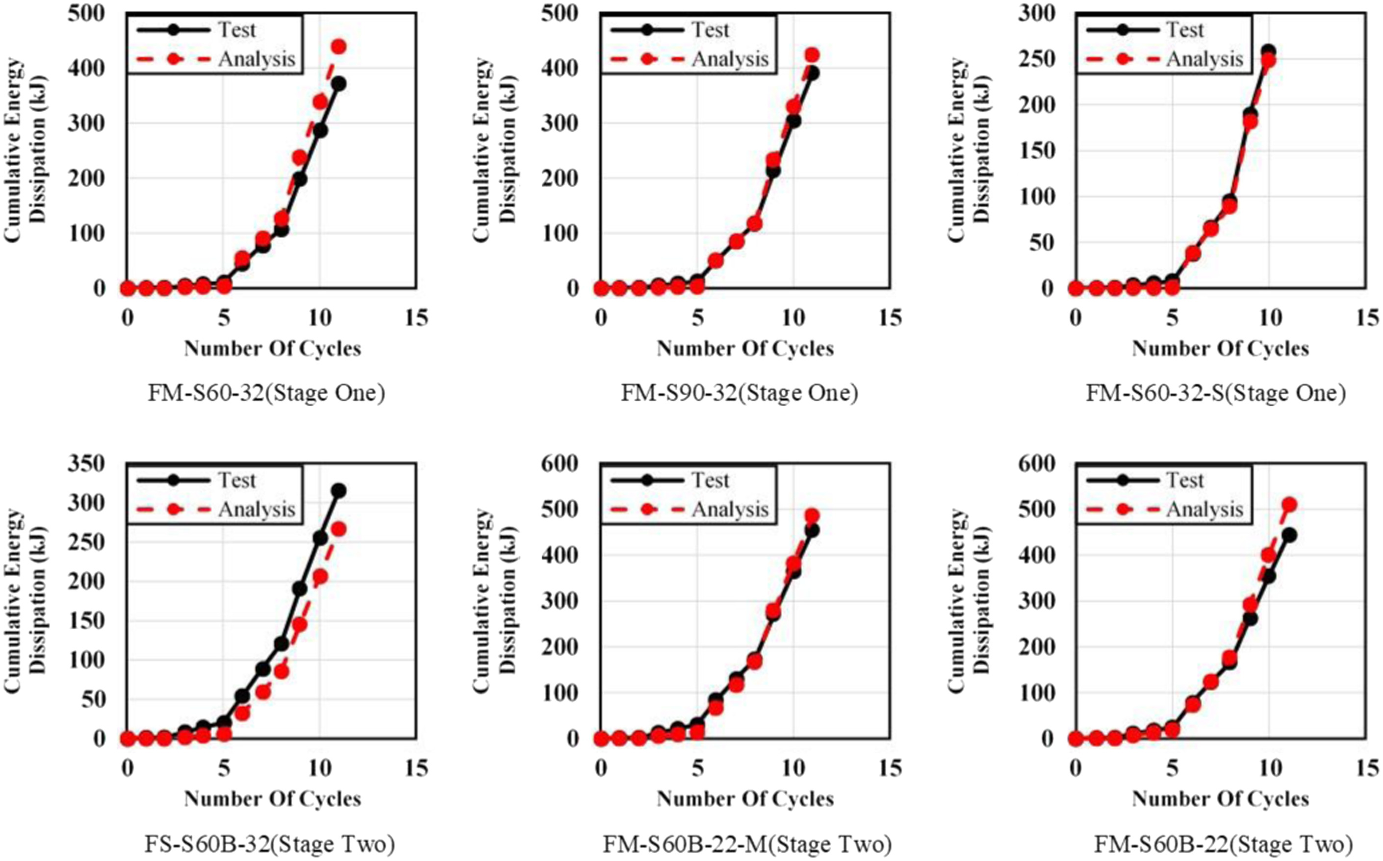
The accumulative energy dissipation, obtained by calculating the area under the hysteresis loops, between the numerical and test results is compared in Fig. 19, which also indicates good agreement at all test cycles.
As described previously, overall, the numerical model provided reliable predictions for the behavior of all the specimens. Since the model’s predictions can reproduce the empirical test results, including the unloading paths, the model could be applied to the seismic analysis of a structure that consists of such a hybrid system in future studies.
Conclusions
This paper reports the test results and numerically simulated performance of a CLT-steel hybrid system using concealed steel plates and drift pins as wall-to-frame connections in different configurations. A nonlinear finite-element model was developed using SNAP V7.0 for the purpose of simulating the experimental results and as a basis for making further predictions for the hysteresis of the hybrid system. Three main elements in the model were made of the frame, the CLT panels, and the frame-panel connections to reproduce the experimental results accurately. The load-displacement curves, load sharing effect between the steel frame and CLT infill, and energy dissipation obtained from the experiment were used to compare to the numerical results to verify the numerical model. Overall, the results of the numerical model did reliably agree with the experimental results in all comparisons. Such validation of the numerical model by the experimental results means that the model is a method to serve as a tool for designing such wood-steel hybrid structures, intended for applications as lateral load resisting systems for medium- to high-rise buildings, in which CLT shear wall infilled steel frames are applied. In addition, for further studies, the numerical model may be used to conduct seismic analyses to determine appropriate -factors, which are required when designing such structures.
Data Availability Statement
Some or all data, models, or code that support the findings of this study are available from the corresponding author upon reasonable request.
Acknowledgments
The authors gratefully acknowledge the Japanese Forestry Agency for supporting this research. The authors would like to thank Ms. Kanazawa Kazumi at the R&D Institute of the Takenaka Corporation and Mr. Li Rui at Kozo Keikaku Engineering for conducting the element tests required to obtain the input values for the numerical model.
References
AIJ (Architectural Institute of Japan). 2006. AIJ standard for structural design of timber structures. [In Japanese.] Tokyo: AIJ.
AIJ (Architectural Institute of Japan). 2019. AIJ standard for allowable stress design of steel structures. [In Japanese.] Tokyo: AIJ.
BSI (British Standards Institution). 2014. Eurocode 5: Design of timber structures—Part 1-1: General—Common rules and rules for buildings. BS EN 1995-1-1:2004+A2:2014. London: BSI.
Committee of CLT Manual. 2016. Design and construction manual for CLT buildings. [In Japanese.] Tokyo: Japan Housing and Wood Technology Center.
Fukumoto, K., and H. Isoda. 2021. “Study on compressive stress transfer in joints of steel frame hybrid structure with CLT infill shear walls.” [In Japanese.] J. Struct. Constr. Eng. 86 (788): 1440–1451. https://doi.org/10.3130/ajis.86.1440.
Fukumoto, K., M. Kouda, K. Kubo, T. Usami, A. Kitamori, Y. Miyauchi, and H. Isoda. 2021. “Experimental study on CLT seismic panel infilled within steel frame.” [In Japanese.] J. Struct. Constr. Eng. 86 (787): 1345–1356. https://doi.org/10.3130/ajis.86.1345.
Fukumoto, K., M. Kouda, M. Saito, T. Okazaki, H. Isoda, and N. Yasui. 2020. “A case study and future subjects of steel frame hybrid structure with CLT infill shear walls.” [In Japanese.] AIJ J. Technol. Des. 26 (64): 923–928. https://doi.org/10.3130/ajit.26.923.
Japanese Cabinet Secretariat. 2022. “Number of buildings completed utilizing CLT panels.” [In Japanese.] Accessed December 13, 2022. https://www.cas.go.jp/jp/seisaku/cltmadoguchi/pdf/clt_expl1.pdf.
Kanazawa, K., H. Isoda, A. Kitamori, T. Usami, and Y. Araki. 2021. “Structural performance of composite structure with CLT wall infilled in steel frames using drift-pin with steel plate.” [In Japanese.] J. Struct. Constr. Eng. 86 (788): 1430–1439. https://doi.org/10.3130/ajis.86.1430.
Li, Z., M. He, F. Lam, and M. Li. 2015. “Load-sharing mechanism in timber-steel hybrid shear wall systems.” Front. Struct. Civ. Eng. 9 (2): 203–214. https://doi.org/10.1007/s11709-015-0293-y.
Li, Z., M. He, F. Lam, M. Li, R. Ma, and Z. Ma. 2014. “Finite element modelling and parametric analysis of timber-steel hybrid structures.” Struct. Des. Tall Special Build. 23 (14): 1045–1063. https://doi.org/10.1002/tal.1107.
Li, Z., M. He, X. Wang, and M. Li. 2018. “Seismic performance assessment of steel frame infilled with prefabricated wood shear walls.” J. Constr. Steel Res. 140 (Jan): 62–73. https://doi.org/10.1016/j.jcsr.2017.10.012.
Li, Z., X. Wang, M. He, W. Dong, and H. Dong. 2019. “Seismic performance of timber-steel hybrid structures. I: Subassembly testing and numerical modeling.” J. Struct. Eng. 145 (10): 04019113. https://doi.org/10.1061/(ASCE)ST.1943-541X.0002395.
Matsunaga, Y., I. Soda, and Y. Miyazu. 2008. “Modeling of restoring force characteristics of wooden structures and its application to dynamic analyses.” In Proc., 78th Architectural Research Meetings, 201–204. Tokyo: Architectural Institute of Japan.
Meng, L., K. Ohi, and K. Takanashi. 1992. “A simplified model of steel structural members with strength deterioration used for earthquake response analysis.” [In Japanese.] J. Struct. Constr. Eng. 437 (Aug): 115–124. https://doi.org/10.3130/ajisx.437.0_115.
Nakashima, S., K. Kitamori, Y. Araki, and H. Isoda. 2016. “Effect of array on tensile load carrying capacity CLT drift pinned joint.” In Proc., World Conf. on Timber Engineering, Vienna 2016”, 740–747. Kolkata, West Bengal: Thinkwood.
Ohi, K., Y. Chen, and K. Takanashi. 1992. “An experimental study on inelastic behaviors of H-shaped steel beam-columns subject to varying axial and lateral loads.” [In Japanese.] J. Struct. Constr. Eng. 38B (Aug): 421–430.
Shi, Y., M. Wang, and Y. Wang. 2011. “Analysis on shear behavior of high-strength bolts connection.” Int. J. Steel Struct. 11 (Jun): 203–213. https://doi.org/10.1007/s13296-011-2008-0.
Stiemer, S. F., S. Tesfamariam, E. Karacabeyli, and M. Propovski. 2012. “Development of steel-wood hybrid systems for buildings under dynamic loads.” In Proc., 7th Int. Specialty Conf. on Behaviour of Steel Structures in Seismic Areas (STESSA). Abingdon, UK: CRC Press.
Tesfamariam, S., S. Stiemer, C. Dickof, and M. Bezabeh. 2014. “Seismic vulnerability assessment of hybrid steel-timber structure: Steel moment resisting frames with CLT infill.” J. Earthquake Eng. 18 (6): 929–944. https://doi.org/10.1080/13632469.2014.916240.
Vertes, K., and M. Ivanyi. 2004. “Determination of the main characteristics of semi-rigid beam-to-column connections through numerical and experimental method.” High Perform. Struct. Mater. 2 (76): 678–684. https://doi.org/10.2495/HPSM040651.
Information & Authors
Information
Published In

Journal of Structural Engineering
Volume 149 • Issue 9 • September 2023
Copyright
This work is made available under the terms of the Creative Commons Attribution 4.0 International license, https://creativecommons.org/licenses/by/4.0/.
History
Received: Sep 15, 2022
Accepted: Mar 3, 2023
Published online: Jun 16, 2023
Published in print: Sep 1, 2023
Discussion open until: Nov 16, 2023
Authors
Metrics & Citations
Metrics
Citations
Download citation
If you have the appropriate software installed, you can download article citation data to the citation manager of your choice. Simply select your manager software from the list below and click Download.