Development and Laboratory Scalability of Ultraviolet-Activated Silica-Based Granular Media as an Engineered System for the Degradation of Per- and Polyfluoroalkyl Substances in Concentrated Liquid Waste
Publication: Journal of Environmental Engineering
Volume 149, Issue 9
Abstract
Lab-based experiments were performed to develop an engineered column system for ultraviolet silica-based granular media (UV/SGM) to degrade per- and polyfluoroalkyl substances (PFAS) in concentrated liquid waste and challenge the laboratory scalability of the system and develop a field-applicable system. UV/SGM is an innovative photocatalyst developed to degrade a variety of PFAS compounds and predominantly designed to treat low-volume highly concentrated waste. Scalability is presented by increased system wattage, volume, or flow rate at the lab scale. The resulting reactor configuration presents a proportional UV wattage to treatment volume and relative flow rate as pilot-scale treatment conditions. Treatment efficiency was established by amending concentrated PFAS waste in both strong acid () and strong base (pH 13). UV/SGM takes advantage of the high affinity of silicon and fluorine, which overcomes Coulombic interactions in a high-pH solution for most fluorotelomers and perfluoroalkyl sulfonic acids (PFSAs), whereas increased adsorption/degradation of perfluoroalkyl carboxylic acids (PFCAs) occurs under low pH. Final reactor configurations presented in the study improved the efficiency of UV/SGM to degrade fluorotelomers and PFSAs under basic conditions while taking advantage of photolysis to degrade PFCAs. The system demonstrated degradation of total PFAS in a PFAS-spiked deionized water. Electrical energy per log order reduction (EE/O) calculated by reduction of PFAS ranged from to ; however, fluoride recovered increased, respectively, with EE/O for systems of equivalent flow rate. Therefore, evaluating EE/O based on complete defluorination, rather than parent PFAS removal, could aid in technology energy comparison.
Introduction
Per- and polyfluoroalkyl substances (PFAS) have been used to impart oil and water repellency, temperature resistance, and friction reduction to a wide range of products used by consumers and industry (Mueller and Yingling 2017). Point sources of PFAS releases to the environment include, but are not limited to, military installations, where aqueous film–forming foams (AFFF) are used, and PFAS manufacturing facilities (Davis et al. 2007; ITRC 2020; Backe et al. 2013). Recent research has focused on the continued release and transport of PFAS from AFFF-impacted or PFAS-impacted soils, concrete, and asphalt to stormwater runoff, as well as PFAS migration in groundwater and landfill leachate (Davis et al. 2007; Awad et al. 2011; Høisæter et al. 2019; Guelfo and Higgins 2013; Allred et al. 2015; Maizel et al. 2021; Thai et al. 2022).
Several PFAS may pose a risk to the health of humans and the environment due to their bioaccumulative nature, persistence, and possible toxicity (Conder et al. 2008; Podder et al. 2021). Suspected human health risks based on published literature include pregnancy complications (Zheng et al. 2021; Blake and Fenton 2020), child development (Harris et al. 2021), and thyroid disruptions (Coperchini et al. 2017; Andersson et al. 2019). As regulatory limits for several PFAS are instated, efforts are directed toward improving PFAS treatment technologies (USEPA 2021).
PFAS treatment technologies currently operating at full-scale rely on sequestration via ion exchange (IX) (Fang et al. 2021; Liu and Sun 2021), granular activated carbon (GAC) (Sonmez Baghirzade et al. 2021), filtration (nano or ultra) (Boo et al. 2018; Olimattel et al. 2021) and/or reverse osmosis (Kanchanapiya and Tantisattayakul 2022), or a combination thereof (Franke et al. 2021; Murray et al. 2021). The sequestered PFAS and other concentrated waste streams are typically taken off-site for thermal treatment to destroy PFAS using incineration. Incineration has been shown to release undesired by-products, such as short-chained PFAS, in the air (Buss 2021).
Several destructive technologies have been demonstrated at pilot scale, including smoldering combustion (Duchesne et al. 2020), ultraviolet (UV)/sulfite (Liu et al. 2021), electrochemical oxidation (Linang et al. 2022; Maldonado et al. 2021), and plasma (Nau-Hix et al. 2021). Excluding smoldering combustion, the field-demonstrated destructive technologies are coupled with pump and treat sequestration technologies, with the destructive technology treating a concentrated liquid waste produced as a by-product of regeneration. Other destructive technologies that have yet to be demonstrated at field sites or are transitioning to field demonstrations include hydrothermal treatment (Wu et al. 2019; Hao et al. 2021), heat-activated persulfate (Bruton and Sedlak 2017; Shojaei et al. 2021), and pyrolysis (Buss 2021; Alinezhad et al. 2022). Electron beam (Feng et al. 2021) and non-heat-activated persulfate (Londhe et al. 2021) have been laboratory-tested and validated to degrade at least some PFAS.
Destruction of PFAS using photolysis, photocatalysis, or combined approaches also have promise for onsite PFAS treatment. Doped or modified photocatalysts have been developed to degrade a variety of PFAS (Parenky et al. 2020; Sahu et al. 2018; Qian et al. 2021; Zhu et al. 2021; Li et al. 2020; Xu et al. 2017). Photocatalysts are usually mixed into a slurry for treatment, which requires additional nanofiltration to retrieve the catalyst, or fixated within thin films, which only have one reactive side. Slurry and thin-film photocatalytic treatment technologies have not yet been demonstrated to degrade complex PFAS waste streams, show significant reductions in degradation kinetics when moved to real PFAS waste, or simply have yet to be scaled up for field applications. Perfluoroalkyl carboxylic acids (PFCAs) can be degraded by photolysis alone; perfluoroalkyl sulfonic acids (PFSAs) and perfluoroalkyl acid (PFAA) precursors are more recalcitrant (Qanbarzadeh et al. 2021). The development of a photocatalyst that could degrade PFAS mixtures present within a waste stream could have multiple applications to benefit industry, human health, and the environment.
The performed study addressed the following three overarching objects to progress the understanding of necessary conditions and applications for UV-activated silica-based granular media (UV/SGM) treatment to degrade PFAS in concentrated liquid waste: (1) determine what treatment type and pH degrade both PFCAs and PFSAs, (2) determine what treatment conditions effect degradation kinetics, and (3) validate degradation of a mixture of highly concentrated PFAS solution within a reactor capable of transitioning into field applications. Addressing these objectives was achieved by testing UV/SGM treatment in a variety of reactor configurations designed to test individual aspects of the overall objectives.
Previous studies (McIntyre et al. 2021, 2022), have evaluated UV/SGM treatment in no-flow or mini flow-through reactors in basic conditions only (). The influence of pH was further evaluated in the study to include in batch reactors before beginning to scale the technology. Two different photocatalysts, bismuth trioxide and titanium dioxide, were tested in the initial phases of this study. Subsequent reactors consisted of engineered column systems designed and fabricated to not only scale the technology but evaluate additional treatment parameters. Flow-through reactors varied UV wattage in a low-flow system. Recirculation reactors assessed the influence of flow rate on degradation kinetics while developing a system that was applicable for field application. Photocatalysis versus photolysis was assessed in both column reactor designs.
Based on initial degradation results for perfluorooctane sulfonate (PFOS) and perfluorooctanoic acid (PFOA), modifications to the recirculation reactor occurred before challenging the UV/SGM system with spiked deionized water containing nine different PFAS. Although significant scale-up of UV/SGM treatment is demonstrated in this study, it is important to note that the reactor volume was contained to 1 L for the lab setting. A linear extrapolation of the recirculation reactor configuration parameters validates that UV/SGM can continue to be scaled beyond the extent of this study to treat highly concentrated and low-volume PFAS liquid waste.
Materials and Methods
Chemicals
Chemical reagents used throughout this study during media synthesis, experimental studies, and sample analysis are listed in the Supplemental Materials. PFAS solutions were mixed using the listed reagents and deionized water (18.2 MΩ). PFAS concentrations for the mixed solution are presented in Table S1 .
Silica-Based Granular Media
The SGM was developed to degrade organic contaminants in previous studies (McIntyre and Hart 2021), specifically PFAS (McIntyre et al. 2021, 2022). SGM is an innovative destructive technology for PFAS that has been demonstrated to defluorinate fluorotelomers, PFSAs, and PFCAs (McIntyre et al. 2021, 2022). The unique composition of the SGM allows PFAS to adsorb to the silica structure, which is fixed with a photocatalyst, creating an effective transport path for free radicals to attack and degrade the PFAS under the presence of UV light. The porous, lightweight, granular media is developed through a sol-gel process in which tetraethyl orthosilicate (TEOS), silicic acid, deionized water, and titanium dioxide (or another photocatalyst) are combined through heating and stirring. This process continues until a cross-linked polymer is formed. The polymer gel is then broken into the desired gradation and soaked in sodium hydroxide to introduce hydroxyls as a foaming agent. The media is then fired to evaporate the solvent while activating the foaming agent, creating a highly porous granular media. The SGM achieves a pH of 12 in a ratio of SGM:deionized water (DI) water due to the residual hydroxyls from synthesis.
Bismuth SGM
Previous studies with SGM have contained titanium dioxide (Ti-SGM) (McIntyre et al. 2021, 2022; McIntyre and Hart 2021). For this study, SGM was also synthesized with bismuth trioxide (Bi-SGM) to determine if other photocatalysts are as effective or possibly more effective for PFAS degradation. Because the density of bismuth trioxide is much higher than titanium dioxide, the bismuth trioxide was first dissolved in nitric acid before adding TEOS, silicic acid, and deionized water. Dissolving the bismuth trioxide in acid resulted in a color change of the powder from yellow to white. The bismuth SGM version gelled in 2 days, 1 day longer than the titanium dioxide variation. After adding sodium hydroxide, the gelled media again turned yellow in color, indicating that high pH precipitated the bismuth as .
Reactor Configurations
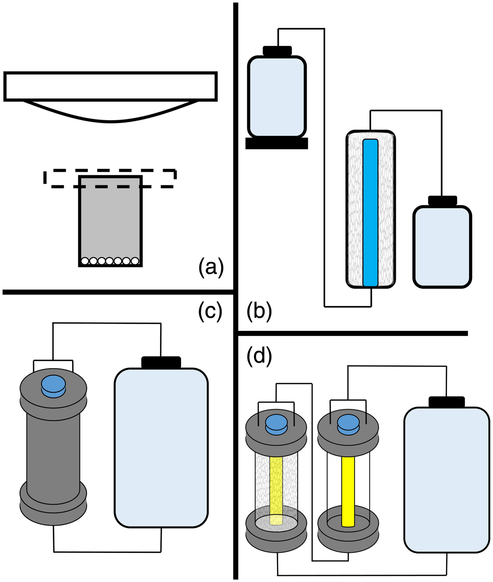
To validate the required conditions for UV/SGM treatment, system improvements, and laboratory scalability, four reactor configurations (Fig. 1) were evaluated; each successive reactor design increasing either the treated volume, flow rate, or both. Batch reactors were originally designed to validate UV/SGM’s ability to degrade PFOS in previous studies (McIntyre et al. 2021). Therefore, the batch reactors were used as an initial baseline for this study to assess pH influence. Flow-through reactors not only increase the volume of the reactor but allow the lamp to be submerged within the reactor, allowing for UV wattage to be assessed in a scalable design. The recirculation reactor keeps the same fundamental design of the flow-through reactor while increasing the flow rate. Photocatalysis, photolysis, and adsorption of PFAS were evaluated in both the recirculation and modified recirculation reactors. Although additional reactor configurations could be assessed to scale and optimize the technology, these configurations allow degradation kinetics to be compared over a variety of system parameters to be used for future design and modification.
Stock solutions of both a combined PFOS and PFOA solution (PFOS/PFOA solution) and a PFAS mixture (PFAS mix) solution were mixed at the start of the study using deionized water. Appropriate dilutions were performed based on the reactor volume to have a final concentration of PFOS and PFOA for the PFOS/PFOA solution. The PFAS mix solution was only used in the modified recirculation reactor experiments and was diluted 10 times from the stock solution. Final concentrations are presented in Table S1 . Sample aliquots of 100 μL and 1 and 10 mL were taken for the batch reactor, flow-through reactor, and recirculation/modified recirculation reactor, respectively. Acidic and basic amendments were added to the UV/SGM treatment to model a coupled photocatalytic and nucleophilic attack on PFAS (basic amendment) or increase the adsorption rate and subsequent degradation rate by creating a positive charge on the SGM (acidic amendment).
We used 1 M solutions of sodium hydroxide (NaOH) and sulfuric acid () for the basic and acidic amendments, respectively. Specific amendment addition methods varied based on reactor configuration. Due to residual hydroxyls from SGM synthesis, controls using no amendments still resulted in a final pH of approximately 12, consistent with previous studies (McIntyre et al. 2021). The solution temperature in all reactor configurations was maintained to be below 30°C. Table 1 defines the variable parameters in each reactor configuration. All experiments were performed in duplicate, controlling for reactor and reactor setup, SGM mass, UV lamp, and amendment addition between each experiment pair. Data figures present average results between duplicate experiments, with error bars denoting minimum and maximum values.
| Reactor configuration | Treated volume | Flow rate | Flow pattern | Lamp wattage | Lamp orientation | Residence timed (min) |
|---|---|---|---|---|---|---|
| Batch | 35 mL | N/A | Batch | 150a | Above reactor | 180 |
| Flow-through | 500 mL | Flow-through | 21b, 57b, 85c | Submerged | 75 | |
| Recirculation | 2–5 L | 14.4 L/min. (3.8 GPM) | Batch | 85c | Submerged | 180, 1,440 |
| Modified recirculation | 5 L | 1.9, 3.8, 8.3 L/min. (0.5, 1.0, 2.2 GPM) | Batch | 85c | Submerged | 1,440 |
a
Broad spectrum UVA/B/C lamp.
b
UVC lamps.
c
VUV lamps.
d
Eq. (S1 ).
Batch Reactor
Batch reactors [Fig. 1(a)] were constructed using polypropylene vessels and a borosilicate cover. Both Bi-SGM and Ti-SGM were utilized for batch reactor studies. Firsts, 35 mL of the PFOS/PFOA solution was placed over 3 g of SGM. A broad-spectrum UVA/B/C lamp was placed above the reactor. For amendment additions, 10% of the deionized water was replaced with the respective amendment. The batch reactor setup was designed to validate PFAS degradation while assessing the impacts of pH on degradation kinetics. The borosilicate cover and broad-spectrum lamps were not optimal for the UV/SGM interaction. The batch reactor configuration was previously validated for PFOS degradation using Ti-SGM and basic amendments (McIntyre et al. 2021).
Flow-Through Reactor
To transition UV/SGM treatment from the lab design to a field applicable design, packed bed column reactors were fabricated to increase both efficiency and scalability. Photocatalytic packed bed reactors have shown effective results for treating other pollutants (Ida et al. 2014) and are a promising design for UV/SGM. Flow-through reactors [Fig. 1(b)] were constructed of 5 cm (2-in.)-diameter 45.7 cm (18-in.)-long PVC piping with PVC end caps.
UV lamps were encased in a highly transmissive quartz sleeve and placed inside each reactor with SGM packed around it. Each flow-through reactor was packed with approximately 250 g of SGM and had an average pore volume of 500 mL. A Mariotte flask and polypropylene needle valve on the influent port of the column controlled the flow rate, which was set to (empty bed). Then, 2 L of contaminant solution containing PFOS and PFOA were passed through the reactor system a total of three times. The average contact time of the solution was approximately for each pass.
For amendment additions, 10% of the deionized water was replaced with the respective amendment. Three different UV lamps were studied with varying wattage (21, 57, and 85 W) and irradiation wavelength (254 and ). Additional parameters for the UV lamps using in the flow-through reactors and subsequent configurations are available in Table S2 . The submerged UV lamp column reactor design increased UV exposure and transmissivity, allowing for validation of energy usage in the flow-through reactor.
Recirculation Reactor
The recirculation reactor [Fig. 1(c)] consisted of 5 cm (2.5-in.)-diameter, 45.7 cm (18-in.)-long stainless steel 304L columns with National Pipe Thread (NPT) threaded column and end caps. An 85-W vacuum UV lamp was encased in a highly transmissive quartz sleeve and placed inside the reactor with approximately 400 g of SGM packed around it such that the reactor had an average pore volume of 1,000 mL. The recirculation reactor was fixed with a 14.1 L/min. [3.8 gal. per min (GPM)] low-flow positive displacement flexible impeller pump. Wetted parts for the pump included polyester, Buna-N, and stainless steel. A 5-L polypropylene carboy containing 2 to 5 L was used as the PFAS waste stream reservoir and allowed for the system to be recirculated. For amendment additions, 10% of the deionized water was replaced with the respective amendment, unless otherwise specified.
Swagelok valves, fittings, and tubing were used for influent and effluent flow routing and sampling ports. Metal Swagelok components were composed of 316 stainless steel, and any fluorinated sealing material was replaced with polyether ether ketone (PEEK). All threads were sealed with silicone to avoid any PFAS contamination from polytetrafluoroethylene (PTFE) tape. The recirculation reactor was designed as a small-scale version of a field-ready system. The system wattage, flow rate, and treated volume are proportional and/or comparable to many pilot-scale destructive PFAS treatment systems for concentrated waste streams.
Modified Recirculation Reactor
The modified recirculation reactor [Fig. 1(d)] builds on the recirculation reactor design by adding an additional UV-only column. The additional column allows for the assessment of a combined photocatalysis/photolysis treatment system, versus the one-column reactor, which only allows for photolysis and photocatalysis to be individually assessed. Three different flow rates (0.5, 1.0, and 2.2 GPM) were evaluated in the modified recirculation reactor to ascertain the effects of flow rate on degradation kinetics as a part of this study’s second objective. Whereas all previous reactor configurations utilized the PFOS/PFOA solution, the modified recirculation reactor was evaluated using the PFAS mix. Materials for the modified recirculation reactor are listed in the recirculation reactor section.
Sample Preparation and Analysis
Sample preparation and liquid chromatography tandem mass spectrometry (LC-MS) analysis of PFAS met criteria specified in the Department of Defense (DoD) Quality Systems Manual (QSM) Table B-15 (USDOD 2019) version 5.3. Sample aliquots of 100 μL were taken from each sample, placed into 1.5-mL polypropylene microcentrifuge tubes, and stored at until LC-MS analysis occurred. Samples were usually analyzed within 24 h and were held for a maximum of 14 days. Sample aliquots were vortexed for 30 s and then centrifuged at 20,800 relative centrifugal force (rcf) for 30 min at a temperature of 4°C. A 20-μL aliquot of the centrifuged supernatant sample was then added to 180 μL of Solvent S ( glacial acetic acid). The resultant solution (Solution A) was mixed and centrifuged again under the same conditions.
Parent PFAS were analyzed by preparing 1,000-time dilution samples by adding 2 μL of the resultant Solution A in 198 μL of Solvent S. PFAS by-products were analyzed by preparing 100-time dilution samples by adding 20 μL of the resultant Solution A in 180 μL of Solvent S. Wellington standard MPFAC MXA was added to Solvent S as an internal standard, with each sample containing of mass-labeled PFAS. Solutions were then vortex mixed and transferred to 100-μL polypropylene inserts in amber-colored autosampler vials. Serial dilution was performed with the zero-time point to determine the desired sample concentration for the calibration curve, limit of detection (LOD), and limit of quantitation (LOQ).
Liquid chromatography was performed on Shimadzu Nexera XR (40-Series) ultrahigh-performance liquid chromatography (UHPLC) system, and high-resolution full-scan mass spectrometric analysis was done on a Shimadzu 9030 quadrupole time of flight (QTOF) mass spectrometer coupled with dual ion source (DUIS) ionization source under negative polarity. An aliquot of 1 μL was injected on an Agilent InfinityLab Poroshell 120 ED-C18 analytical column (100-mm length, 2.1-mm internal diameter, and 2.7-μm particle size). A gradient elution profile of 25-mM ammonium acetate solution in water containing 3% acetonitrile (Channel A) and acetonitrile (Channel B) was used as the mobile phase at a flow rate of (Table S3 ). Details of analytical and instrument parameters are provided in Table S4 .
Each batch contained blank solutions and MPFAC MXA–spiked PFAC-30-PAR Wellington standard throughout the batch as quality assurance and quality control (QA/QC). Blank samples aided in monitoring if carryover was present, whereas the standard monitored variation in retention time and detector sensitivity, in addition to the internal sample within the samples. LabSolutions Insight Explorer was used for data analysis and processing. In addition to monitoring for a suite of 30 PFAS, suspect PFAS screening was performed to identify plausible intermediates or by-products. PFAS limit of detection and limit of quantification are presented in Table S5 . Only long-chained, short-chained, and fluorotelomers were analyzed. Utrashort-chained PFAS were not analyzed in this study; therefore, a complete fluorine mass balance cannot be completed.
Aqueous fluoride was measured using a Dionex ion chromatography system (ICS-90) with system instrumentation described in the Supplemental Materials. Eluent stock solution was prepared consisting of 450 mM sodium carbonate and 80 mM sodium bicarbonate. Then, 20 mL of eluent stock was diluted to 2,000 mL with deionized water ( dilution). Regenerate solution was diluted from 75 mL of 1 M sulfuric acid to 2,000 mL, also with deionized water. Fluoride calibration standards were first prepared as a sodium salt as , which was diluted to final standards of 2, 5, 10, 25, and . Deionized water samples were run as blanks in the analysis sequence and placed between each sample to ensure a conductivity equilibrium baseline was achieved between sulfuric acid–impacted samples. Each sample analysis time was 32.5 min to ensure peak separation with an average pressure of 12,410 kPa (1,800 psi). Sample and standard preparation and analysis, along with quality control samples, were consistent with USEPA Method 300.0 (USEPA 2021).
Results and Discussion
Batch Reactors
Batch reactors were utilized to assess the sec part of overarching objective number 1 (pH on PFAS treatment). Batch reactor experiments were performed over 180 min with both Ti-SGM and Bi-SGM. Sample aliquots of 100 μL were taken at time intervals of 0, 10, 20, 30, 60, 90, 120, and 180 min. Three pH conditions were studied through amendment additions. Sulfuric acid amendment resulted in a pH slightly less than 4 after initial buffering from residual hydroxyls. No amendment SGM treatment reached a pH of 12 because of the residual hydroxyls. Sodium hydroxide amendment had a pH around 13.
The pH of the treatment solution directly impacts the ability of PFAS to adsorb to the photocatalyst. PFAS or constituent of concern adsorption is very important to a photocatalytic treatment considering free radicals are unstable in nature and need a direct pathway to attack the PFAS before recombining. For this study, two different degradation mechanisms are being studied: (1) coupled nucleophile and photocatalytic attack (basic conditions), and (2) enhanced adsorption and subsequent photocatalytic degradation (acidic conditions). Both SGM-only and NaOH amendment utilize the first degradation mechanism, although SGM releases substantially less hydroxyls into solution and could only be contained in a recirculation system.
Fig. 2 presents PFOS and PFOA removal results and subsequent aqueous fluoride recovery for the Ti-SGM. Consistent with previous studies (McIntyre et al. 2021, 2022), PFOS degraded under basic amendments; however, degradation rates were slower in the PFOS/PFOA mixture than in PFOS-only solution. Differences in degradation rates are hypothesized to result from the competition of PFAS for adsorption sites considering two different PFAS are being treated. In Fig. 2(a), pH 12 yielded the highest PFOS degradation. Addition of NaOH to achieve a pH of 13 [Fig. 2(c)] did not increase the degradation kinetics and appeared to hinder the PFOS treatment relative to no amendment. Under acidic conditions (pH 4) [Fig. 2(b)], PFOS degraded at rates that were much slower than in basic conditions. Therefore, it can be theorized that PFOS degradation kinetics are faster under a combined nucleophilic and photocatalytic attack compared with a photocatalytic-only attack.

PFOS has been evaluated by other researchers, supporting that PFOS can overcome electrostatic interactions due to the high affinity of fluorine to silicon (Stebel et al. 2019; Tang et al. 2010). In contrast, PFOA concentrations increased slightly under alkaline conditions [Figs. 2(a and c)]. Acidic conditions [Fig. 2(b)] were the only treatment conditions that yielded degradation of both PFOS and PFOA. Fig. 2(d) depicts fluoride recovery and indicates that the most inorganic fluoride was recovered under no amendment treatment (pH 12) conditions relative to sulfuric acid or sodium hydroxide amendments. Because aqueous fluoride is an anion, some defluorinated species may stay adsorbed to the SGM; however, this was not further evaluated in the study.
Fig. 3 presents PFOS and PFOA removal results and subsequent aqueous fluoride recovery for the Bi-SGM. Remarkably similar trends were observed with the bismuth SGM variation compared with the Ti-SGM, with the main differences being lower aqueous fluoride recovery. Additionally, the Bi-SGM yielded around 10% higher PFOA degradation under acidic treatment conditions [Fig. 3(b)]. PFOA did not degrade in basic pH conditions [Figs. 3(a and c)]. To better understand the effects of pH amendments, Fig. S3 presents the reaction kinetics of the six batch reactor treatments. Reaction kinetics are presented for total PFAS in solution (sum of PFOS and PFOA). Reaction equations can be found in Table S6 .
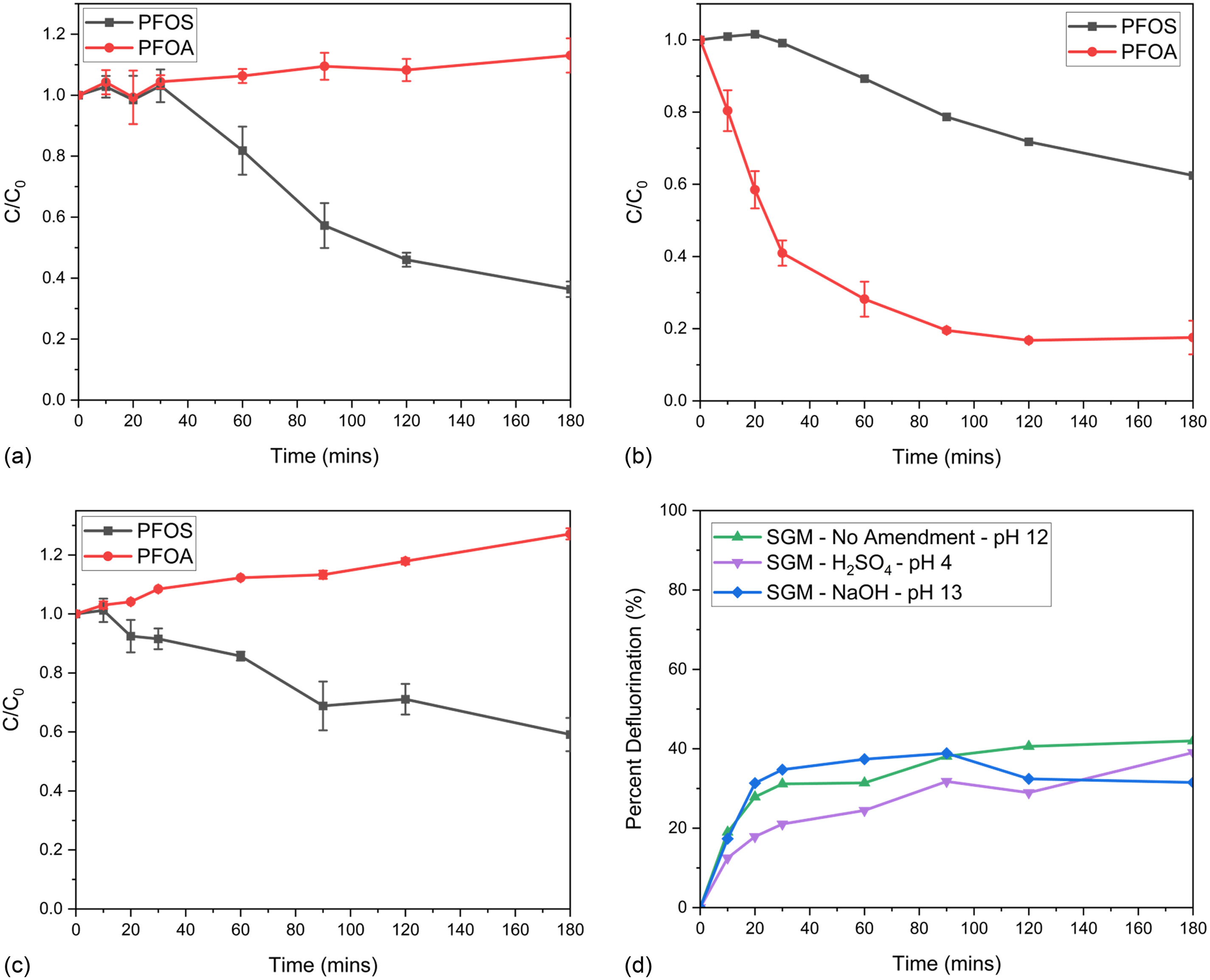
Although PFOS concentrations decreased in all three pH conditions for both Ti-SGM and Bi-SGM, PFOA was only removed under acidic conditions. PFOA increased by an average of 20% under basic conditions. Considering the batch reactor is a no-flow system with a very low initial volume, 35 mL, evaporation could have occurred within the system, resulting in an observed increase in concentration. Although the batch reactor is not reliable or feasible for scale-up, the design gives insight on how PFOS and PFOA are treated under different pH conditions. Batch reactors additionally considered the effects of two photocatalysts on PFAS degradation, bismuth trioxide and titanium dioxide. Due to the similarities in overall PFAS removal, similar costs in Ti-SGM and Bi-SGM synthesis, and considering Ti-SGM synthesis is performed at twice the rate of Bi-SGM synthesis, Ti-SGM was carried forward as the preferred approach in subsequent reactor studies.
Flow-Through Reactor Experiments
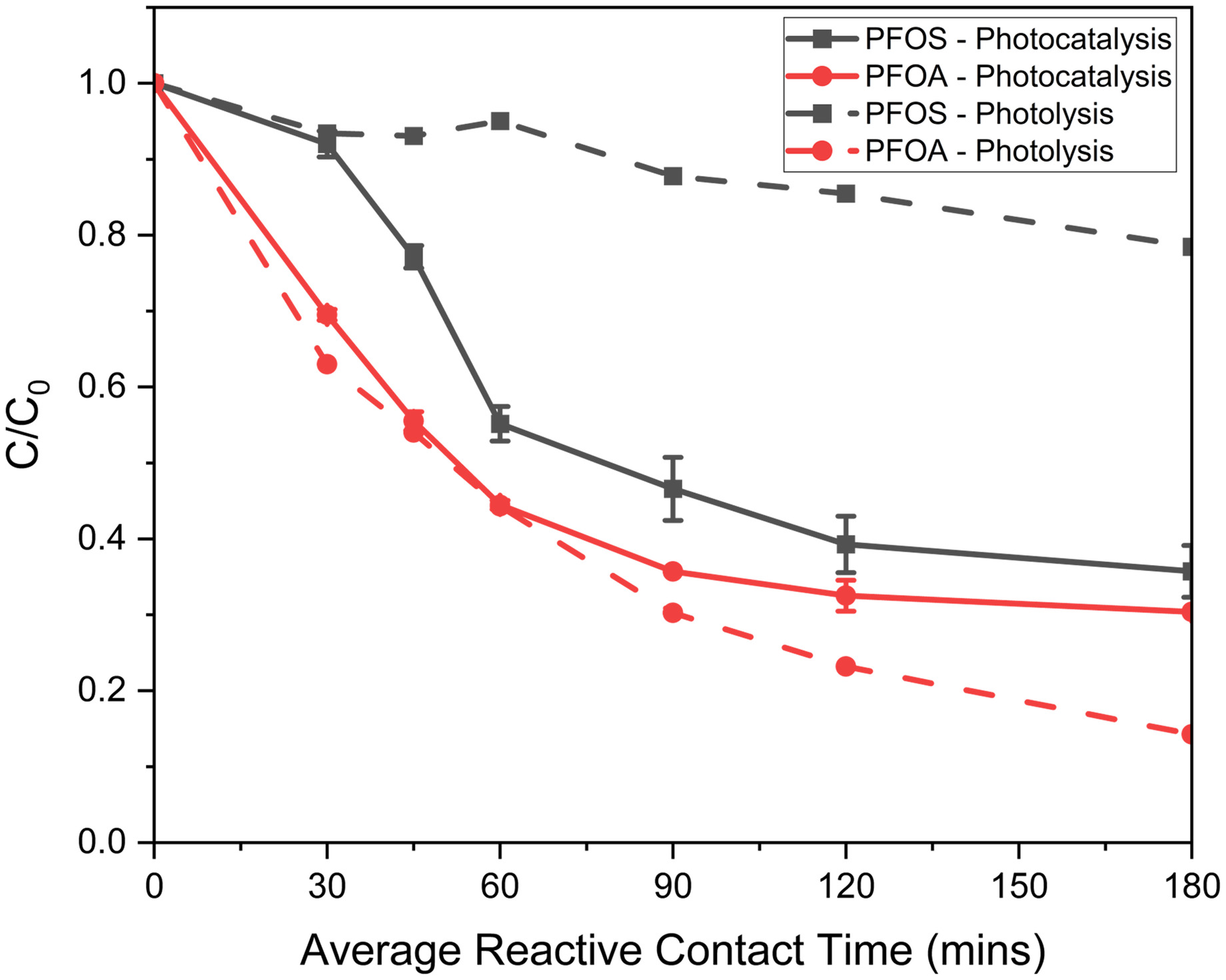
A flow-through reactor with a submerged lamp and packed bed configuration was used to challenge the scalability of SGM and evaluate improvements in efficiency by comparing lamp wattage. Because the acidic amendment was the only treatment that degraded both PFOS and PFOA, only the sulfuric acid was amended in the flow-through reactors. The influence of UV wattage on PFAS degradation and subsequent aqueous fluoride release was assessed with 21-, 57-, and 85-W UV lamps. All other variables, including the mass of SGM, were fixed. Fig. 4 depicts PFOS and PFOA degradation for all three wattage experiments, along with an adsorption control. By-product and fluoride generation are presented for the 57- and 85-W experiments.
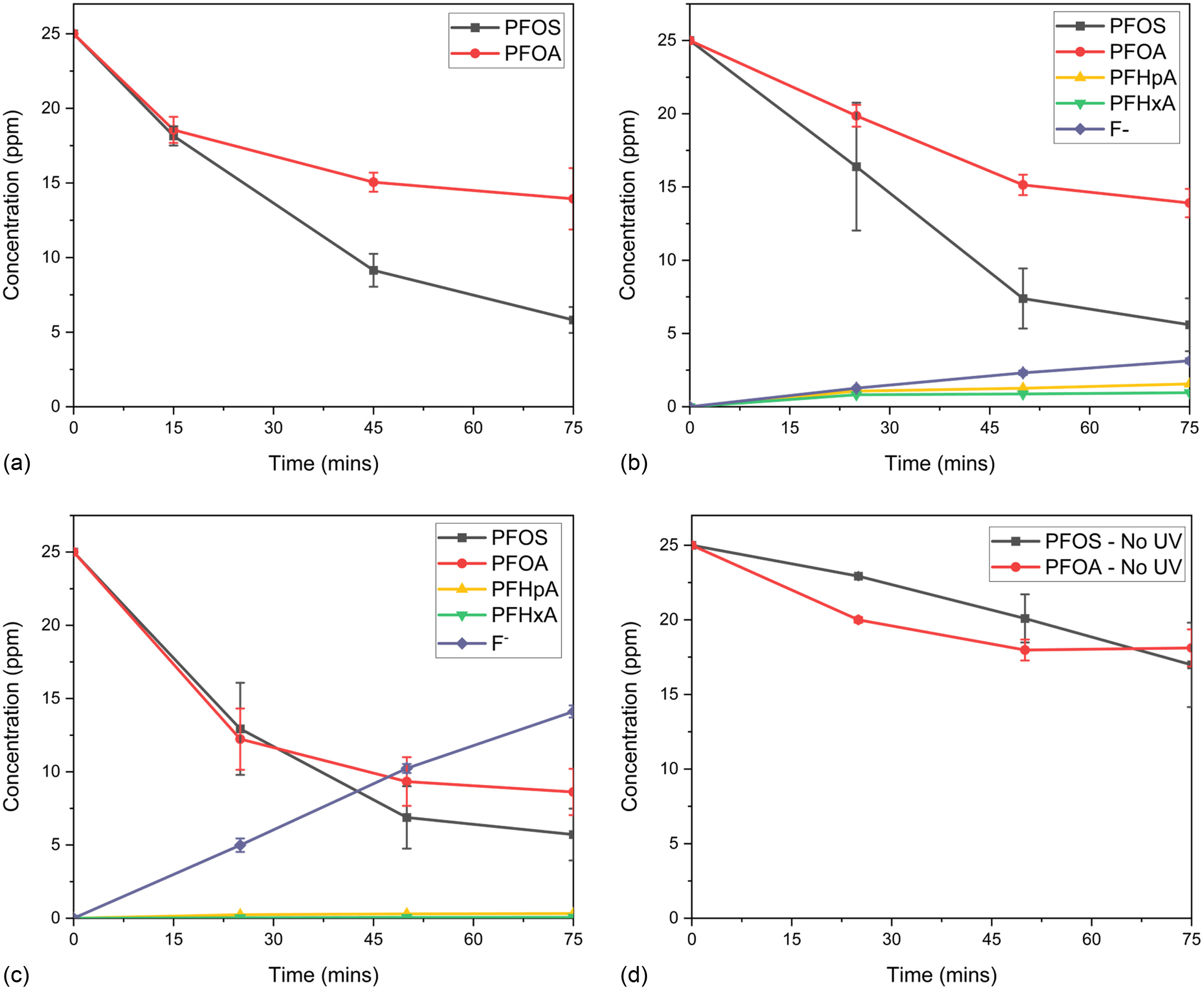
The UV/SGM 21-W lamp reactor removed PFOS 77% and PFOA 46%, resulting 62% total PFAS removal over the 75 min. Similar to the lower wattage lamp, the 57-W lamp reactor degraded PFOS by 78% and PFOA by 46%, resulting in 62% total PFAS removal. Additionally, 9% aqueous fluoride was recovered. The 85-W lamp reactor performed the best, with the removal of 78% PFOS and 66% PFOA, resulting in 72% removal of total PFAS, along with the recovery of 43% aqueous fluoride. Almost five times more aqueous fluoride was recovered in the 85-W reactor versus the 57-W reactor, whereas only 10% more total PFAS was removed. This gives insight that, although PFAS degradation was limited to the rate in which PFAS adsorbs to the SGM, the rate of defluorination could be controlled with UV wattage. The no-UV or dark control yielded some adsorption, 32% PFOS and 28% PFOA, to the SGM.
Fluoride generation and by-product production was not analyzed in the experiments using the 21-W reactor considering a large enough volume was not collected. However, the collected volume was adjusted to 1 mL for subsequent experiments. Shorter-chained PFCA by-products formed with both the 57- and 85-W reactors, along with release of aqueous fluoride, thus validating the degradation breakdown of the PFOS and PFOA. The total fluorine mass balance at 75 min equates to 54% for the 57-W reactor and 72% in the 85-W reactor. Only aqueous fluoride and PFAS in the 18-analyte suite presented in EPA Method 537.1 (Shoemaker and Tettenhorst 2018) were analyzed as possible by-products. Considering acidic amendments create a positive surface charge on the SGM, anionic PFAS by-products could be adsorbed to the SGM. Analysis of fluoride or PFAS by-products adsorbed to the SGM, along with analysis of aqueous and adsorbed ultrashort-chained PFAS, would be required to close the fluorine mass balance.
Comparison between experimental data sets reveals that defluorination was more rapid with the higher wattage lamp, but parent compound degradation rates did not improve proportionally to the increase in wattage. UV/SGM treatment efficiency depends on PFOS and PFOA adsorption to the photocatalyst within the SGM. Increasing the UV wattage may degrade sorbed PFOS and PFOA faster, freeing adsorption sites to treat additional PFAS. The improved ultraviolet-C (UVC) transmissivity of the quartz sleeve improved PFAS degradation rates compared with batch reactor experiments. Although the flow-through reactors operated at a low flow rate of approximately , results began validating the hypothesis that UV/SGM can be scaled and demonstrated improved efficiency from upscaling the reactor configuration.
UVC versus VUV
Other studies have evaluated PFOA degradation, along with other PFCAs, by photolysis, with increased photolysis from vacuum UV (VUV) lamps (Qanbarzadeh et al. 2021). To further evaluate the influence of UVC (254 nm) versus VUV (), no-flow cylinder experiments were assessed with 57-W UVC and 48-W VUV lamps utilizing the reactor presented in Fig. S4 and lamp parameters presented in Table S2 . No amendments or photocatalysts (SGM) were added to the experiments, resulting in the solution being a pH of 7. Quartz sleeves utilized for UVC experiments were approximately 90% transmissive at 254 nm. Quartz sleeves utilized for VUV experiments were approximately 60% transmissive at 185 nm and 90% transmissive at 254 nm. Radiation flux at 185 nm was one-fifth the radiation flux at 254 nm. Eight samples were taken over 720 min, with results depicted in Fig. 5.
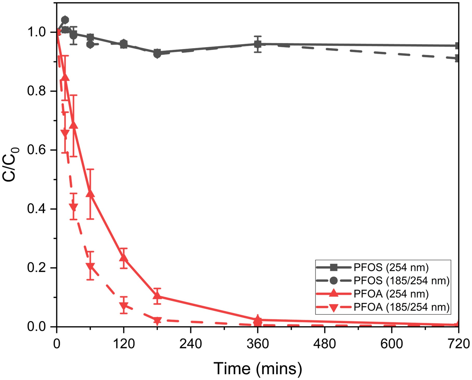
The results support that PFOS cannot be degraded by photolysis, thus emphasizing the need for SGM. PFOA was degraded by both 254 and lamps; however, the VUV lamp resulted in better kinetics. The VUV lamp degraded 80% of PFOA in 60 min, with PFOA below the limit of detection within 360 min. The UVC lamp degraded 55% of PFOA in 60 min and 99.4% in 720 min. Results provide evidence supporting VUV lamps degrade PFOA more efficiently. Additionally, quartz sleeves capable of approximately 85% transmission at 185 nm could be utilized to further improve kinetics, however, a significant increase in cost () would need to be considered. All subsequent experiments utilized 85-W VUV lamps in the reactor design. Photolysis degradation of PFCAs and a combined photocatalysis/photolysis treatment reactor is further assessed in the modified recirculation reactor.
Recirculation Reactor
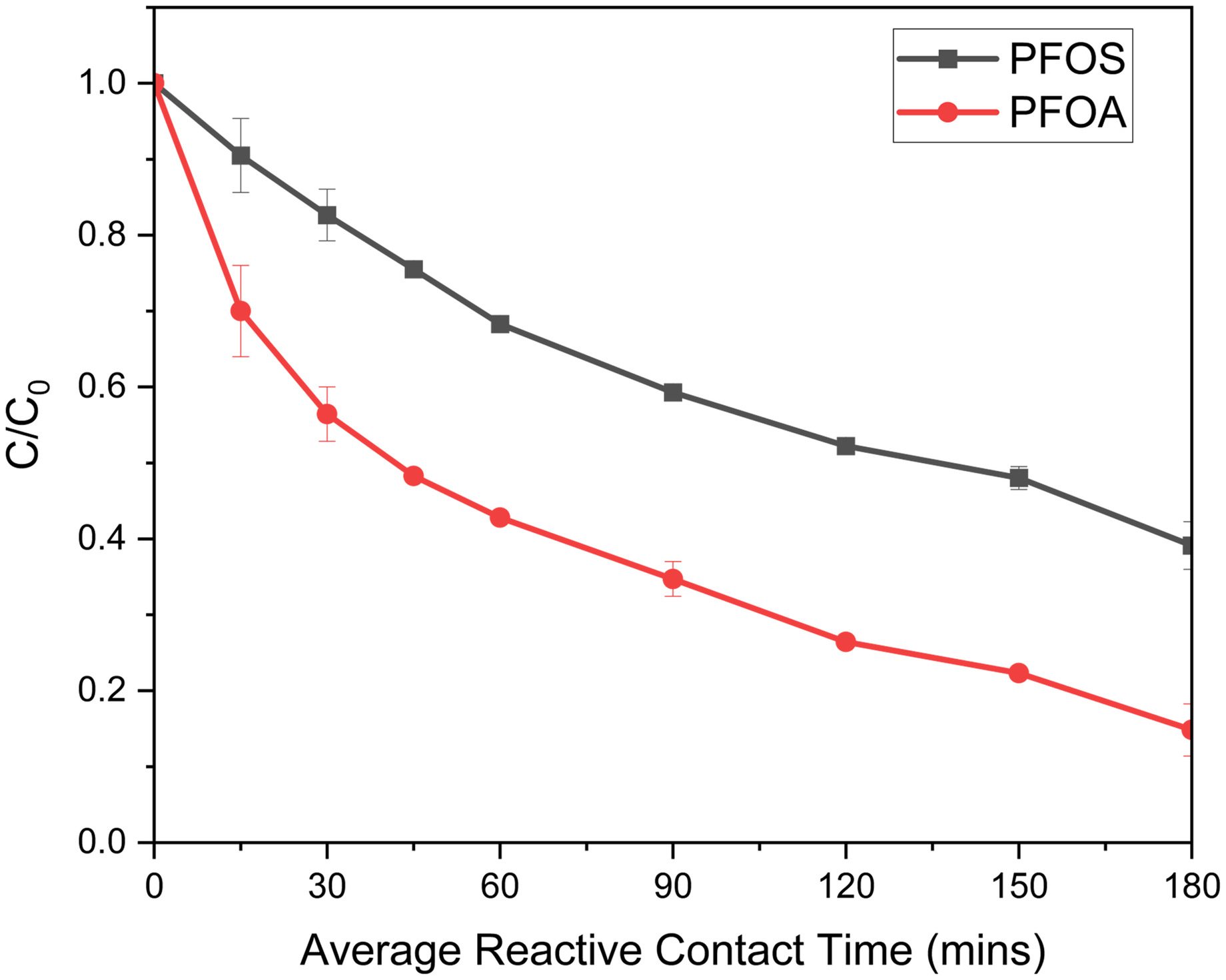
The final assessment of UV/SGM examined optimizing photocatalysis and photolysis treatment, while continuing to scale within the laboratory by increasing the flow rate in a recirculation reactor. The higher flow rate was desired to fully utilize pore space within the reactor and to validate pilot-scale treatment conditions. Fig. 6 presents the removal of PFOS and PFOA in the mixed solution under acidic conditions by photocatalysis (with SGM) and photolysis (no SGM). A total volume of 2 L of solution was cycled through a single column for the photocatalysis experiment. The packed average pore volume was approximately 1 L.
SGM displaced a large volume of solution within the reactor; therefore, 3 L of solution were treated during the photolysis study to maintain a similar average contact time. Approximately 70% of PFOS and PFOA was removed by photocatalysis (SGM present); PFOS and PFOA degraded at similar rates. Photolysis only (no SGM) degraded 15% more PFOA compared with photocatalysis but removed minimal PFOS. Results demonstrate that the presence of SGM is vital for degrading PFOS, whereas PFOA can be degraded by both photolysis and photocatalysis.
Reactor Kinetics Comparison
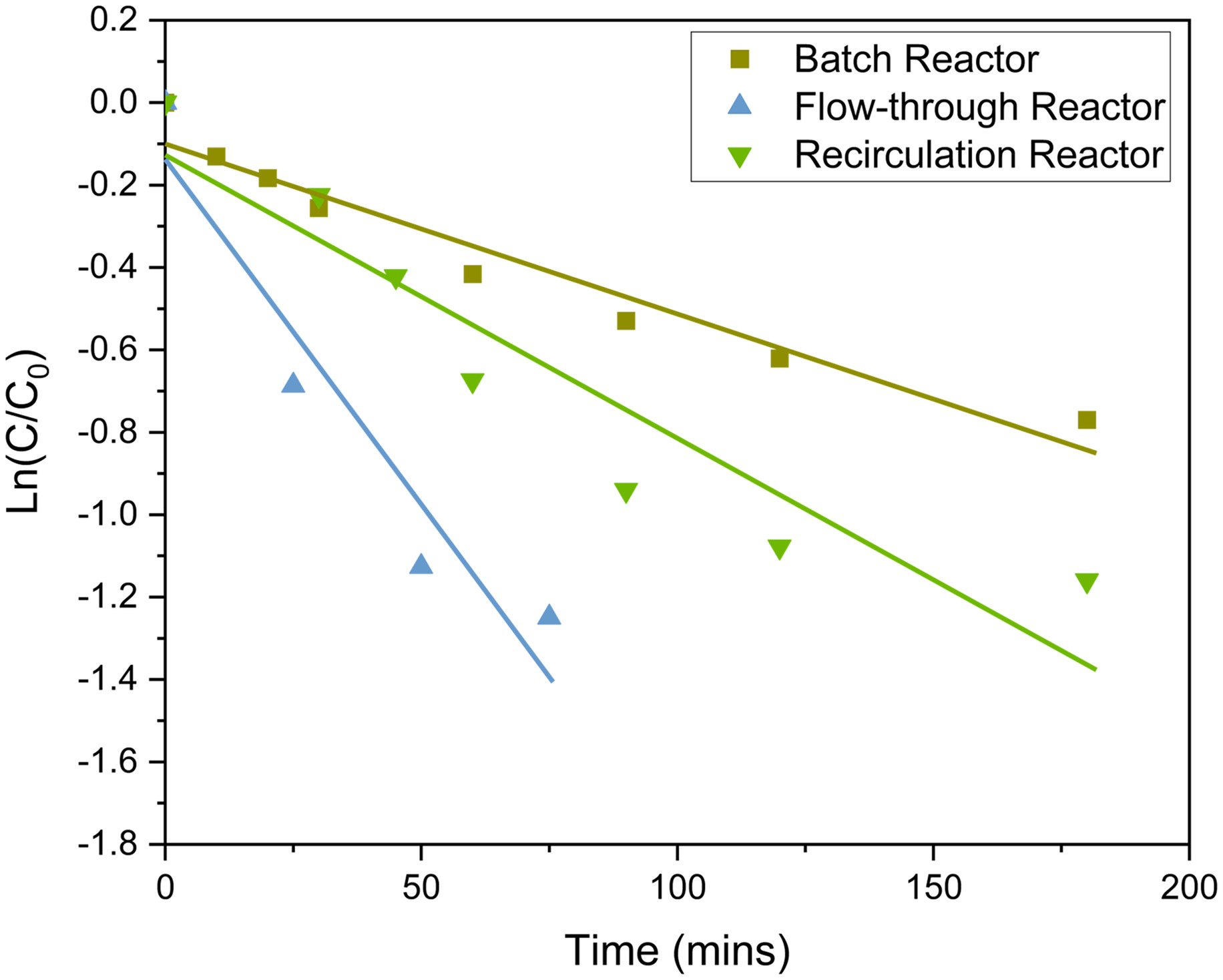
To better understand the differences in removal rates for PFAS, kinetics were calculated using experiment data presented from each reactor configuration. Removal kinetics of total PFAS in all three reactor configurations under acidic conditions are presented in Fig. 7, with kinetic equations in Table S7 . Similar to other studies examining photocatalytic degradation of PFAS (Xu et al. 2020; Yao et al. 2021), removal kinetics of total PFAS followed pseudo-first-order kinetics. Removal kinetics of total PFAS are presented instead of PFOS and PFOA assessed individually, considering most real matrices will consist of a mixture of PFAS. Batch reactors [Fig. 2(b)] had the slowest kinetics, followed by recirculation reactors (Fig. 6), and then flow-through reactors [Fig. 4(c)]. As expected, the flow-through reactors, which have the submerged lamp and a low flow rate, had the highest degradation kinetics. As the flow rate increased, in the recirculation reactor, degradation kinetics become slower.
Modified Recirculation Reactor
Results in this study thus far conclude that PFOS degrades at a faster rate under basic conditions than acidic conditions and PFOA degrades at a similar rate under photocatalysis (acidic conditions) and photolysis (acidic conditions). PFOA did not degrade under photocatalysis (basic conditions) and PFOS did not degrade under photolysis.
To increase both PFOS and PFOA degradation, the recirculation reactor was modified into a two-column system to take advantage of PFOS degradation under photocatalysis (basic conditions) and PFOA degradation under photolysis. One column contained the UV/SGM system and the other only the VUV lamp. No amendments were used for this experiment to determine if the degradation rate of PFOS could be increased under slightly basic conditions, as seen in the batch reactor study, without hindering the photolysis attack on the PFOA. Here, 4 L of solution were recirculated through the two columns. Fig. 8 presents the degradation of the PFOS/PFOA solution under slightly basic conditions.
When compared with Fig. 6, results from the unmodified recirculated reactor yielded PFOA removal consistent with the photolysis only experiment. No hindrance in the photolysis attack was observed under the basic pH experimental conditions. PFOS removal was 10% less in the basic study versus the acidic amendment study, due to a shorter contact time of the solution within the SGM column. In the acidic study (Fig. 6), the solution had 180 min of contact time with the SGM. However, in the basic study (Fig. 8), the solution only had around 90 min. A similar study with an acidic amendment with the two-column system is presented in Fig. S5 where minimal PFOS removal was observed. PFOS had slower degradation kinetics under acidic conditions, and the contact time of PFOS in the SGM reactive column was reduced. Therefore, acidic conditions would only be more efficient for a waste stream with high PFCAs.
Studies in the recirculation reactor provide insight into how the UV/SGM system could be configured and efficiently designed for the degradation of site-specific PFAS waste streams. Comparison of the different treatment types, photocatalysis, photolysis, and combined photocatalysis/photolysis under both acidic and basic conditions for PFOS and PFOA are presented in Table S8 . Photocatalysis/photolysis under basic conditions (Fig. 8) had the most degradation of PFOS and PFOA; however, UV/SGM treatment could be designed based on the PFAS present in each concentrated waste. If a PFAS solution is laden with a higher concentration of PFSAs than PFCAs, more SGM columns could be arranged in series, and the treatment would be performed under basic conditions. If the PFAS solution is laden with higher concentrations of PFCAs, with some PFSAs, the treatment would be performed under acidic conditions to degrade both PFOS and PFOA, as depicted in Fig. 6. The UV/SGM can be configured to target specific PFAS and therefore provides a versatile treatment system for concentrated PFAS solutions.
To begin to demonstrate performance of UV/SGM in a more complex PFAS solution and assess object three, an experiment was conducted with a mixture of FTS, PFSAs, and PFCAs, in the modified recirculation reactor under basic conditions. Here, 5 L of solution containing total PFAS was mixed and amended with 5% NaOH. The solution was recirculated through the modified two-column reactor (one photocatalysis and one photolysis) at 0.5 GPM. Results are presented in Fig. 9, with aqueous fluoride recovery presented in Fig. 9(b) and adsorption and photolysis controls in Fig. 9(c).
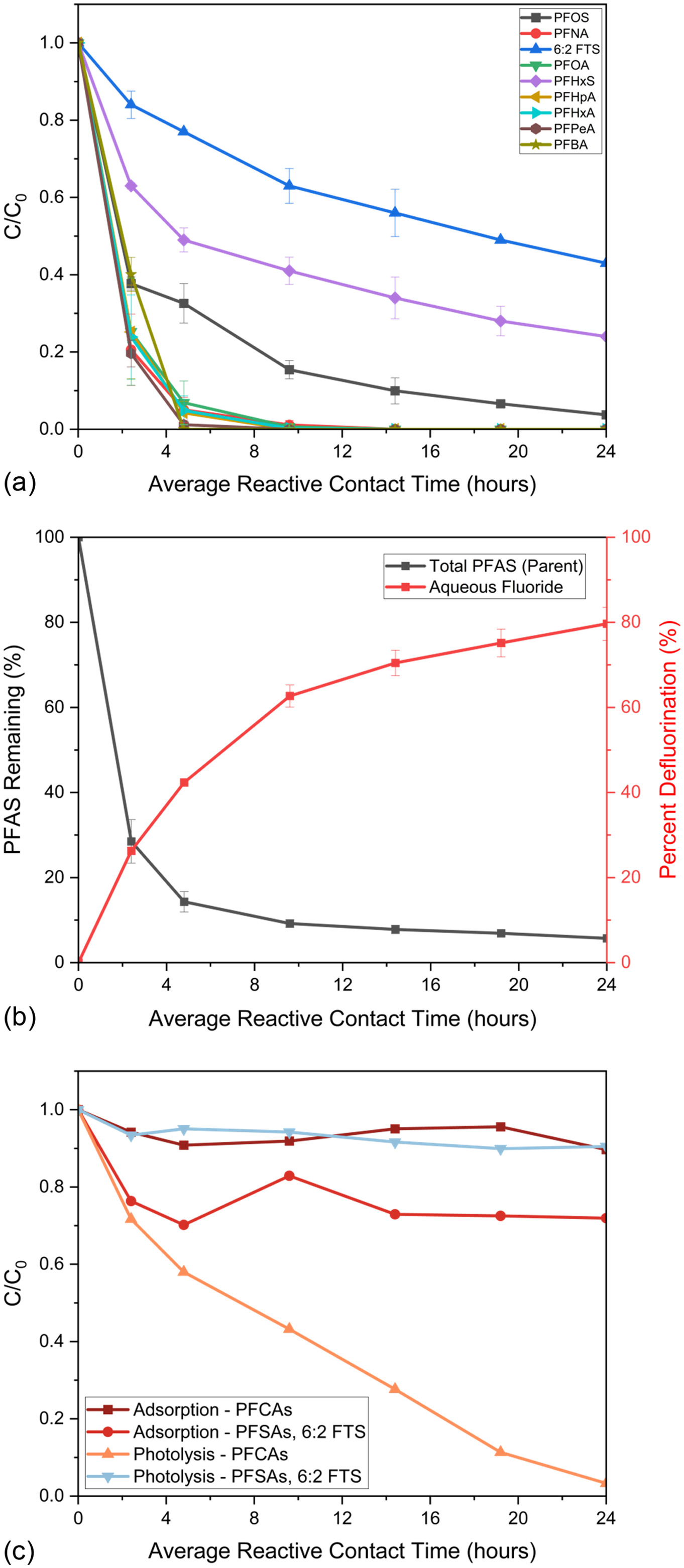
A total of 94% total PFAS were degraded with 80% defluorination. PFCAs were removed at similar rates to previous experiments, but PFSAs and FTS removal rates varied. The photolysis control provides evidence PFCAs were primarily degraded via photolysis. Considering that PFSAs and FTS are not susceptible to degradation by photolysis, these analytes competed for adsorption sites and subsequent degradation in the SGM column. PFCAs could hinder the rate at which analytes could adsorb to the SGM. In the PFAS mixture, PFOS had faster sorption and subsequent degradation rates than shorter-chained PFSAs, along with FTS. Therefore, PFOS would likely need to be removed before PFHxS and 6:2 FTS start adsorbing/degrading more rapidly.
To better understand the influence of flow rate on PFAS degradation, the PFAS mixture solution was treated using two additional flow rates, 1.0 and 2.2 GPM, and the resultant data compared against that of the 0.5-GPM pump. Results for both total PFAS degradation and defluorination are presented in Fig. 10. The 0.5 GPM flow rate resulted in the greatest PFAS degradation and defluorination, followed by the 1.0 GPM flow rate with 86% PFAS degradation and 61% defluorination, and the slowest degradation flow rate was 2.2 GPM with 77% PFAS degradation and 47% defluorination. Flow rate experiments support significant differences in PFAS degradation and defluorination, allowing for another system optimization parameter.

Treatment Comparison and Energy Requirements
In addition to degradation kinetics, energy efficiency is an important consideration when evaluating which destructive technology is best for a specific site or waste stream. Table 2 compares the electrical energy per log order reduction (EE/O) using the equation presented in the Supplemental Materials and inputs presented in Table 1. Five different variations of the submerged lamp reactors studied were compared according to six variables: flow rate, wattage, PFAS matrix complexity, EE/O, PFOS removed, and total fluoride recovered. Although PFOS and PFOA were present in all solutions, PFOS was chosen for EE/O comparison because experimental results indicated that Ti-SGM was solely responsible for PFOS degradation, whereas UV photolysis degraded PFOA in the modified recirculation reactor.
| Variations | 1 | 2 | 3 | 4 | 5 |
|---|---|---|---|---|---|
| Reactor | Flow-through | Flow-through | Flow-through | Modified recirculation photolysis-basica | Modified recirculation photolysis-basicb |
| System wattage | 21 | 57 | 85 | 85 | 85 |
| PFAS matrix | PFOS/PFOA | PFOS/PFOA | PFOS/PFOA | PFOS/PFOA | PFAS Mix |
| Treatment time (min) | 75 | 75 | 75 | 90 | 90 |
| Treated volume (L) | 0.5 | 0.5 | 0.5 | 1 | 1 |
| PFOS in system () | 25 | 25 | 25 | 25 | 4.5 |
| PFOS removed (%) | 80.2 | 85 | 77.2 | 58 | 51 |
| Fluoride recoveredc () | — | 3.1 | 14.2 | 7.6 | 7.0 |
| EE/O () | 74.64 | 172.96 | 265.18 | 338.42 | 411.55 |
a
3.8 GPM flow rate.
b
0.5 GPM flow rate.
c
Total aqueous fluoride in system.
Considering PFOS only degrades with the UV/SGM and not photolysis, only one 85-W lamp was considered for EE/O calculations for the modified recirculation reactor. Pumping power was determined to be less than 1% of the total EE/O, and therefore, not included in the final calculations. EE/O was calculated at 75 min for the flow-through reactor and 90 min for the modified recirculation reactor. For the flow-through reactor, the PFOS/PFOA solution was utilized for all experiments; only the wattage of the system was varied. As the wattage of the system increased, the EE/O also increased; however, the degradation kinetics of PFOS improved only minimally.
A comparison of EE/O values would lead the reader to conclude that lower wattage systems are much more energy efficient. However, based on recovered aqueous fluoride, the higher wattage system demonstrated a much higher percentage of complete defluorination. The EE/O calculation does not account for the partial degradation of longer-chained PFAS into shorter-chained PFAS during the defluorination process. The energy needed to completely defluorinate PFAS is greater than that required for partial degradation to another PFAS. If the contaminant removal ratio is replaced with the inverse ratio of fluoride recovery, the 85-W lamp in the flow-through reactor (Variation 3) would require the lowest amount of energy. When comparing the flow-through rector and modified recirculation reactor under the same PFAS solution and amendment (Variations 3 and 4), the modified recirculation reactor has a higher EE/O. The higher EE/O is attributed to the higher flow rate reducing the PFAS sorption rates and resulted in additional required contact. To lower the EE/O in the modified recirculation reactor, a lower flow rate would be needed. When treating a low-volume, high-PFAS-concentration liquid waste, the need for a high flow rate is less important than degradation kinetics. The EE/O for the PFAS mix for the recirculation reactor was even higher than the PFOS/PFOA solution. This further suggests that PFAS analytes are competing, slowing down the treatment of individual compounds and making the complexity of the PFAS solution important when comparing EE/O values.
Despite requiring design optimization for specific PFAS waste streams to bring down EE/O, both low-wattage and high-volume variations of UV/SGM are still competitive against existing technologies (Nau-Hix et al. 2021; Qanbarzadeh et al. 2021; Singh et al. 2020; Yao et al. 2021). To fully assess and improve the energy requirements of UV/SGM for a field-deployable system, a low-wattage, low-flow system would need to be studied in the recirculation reactor for concentrated PFAS waste.
Environmental and Field Implications
This study demonstrated the ability to move UV/SGM from small 35-mL batch experiments to a scalable packed column reactor that can be configured as either a flow-through reactor or recirculation reactor. Reactor volume did not exceed 1 L during this study; however, the resulting reactor can be proportionally scaled to move into a pilot-scale demonstration. The packed column reactors could be increased in length and skid mounted in series for pilot-scale implementation without impacting treatment kinetics. UV/SGM is designed to treat low-volume, highly concentrated PFAS waste, such as still bottoms, foam fractionate, AFFF stockpiles, and so on; therefore, longer contact times are still feasible for full-scale treatment. Additionally, this study demonstrated that lower flow rates result in faster degradation kinetics.
At a lower flow rate, treatment time could be significantly reduced. Regenerable ion exchange systems are usually regenerated every 6 to 12 months (Linang et al. 2022), giving UV/SGM systems time to deploy and treat still bottoms before the next regeneration. Foam fractionate produces around 1 L of concentrated foam for every 5,000 L of groundwater treated (Nguyen 2021). Foam could be stored and treated via UV/SGM in larger volumes, or UV/SGM could be installed as a treatment train with foam fractionate. Considering concentrated PFAS waste will be relatively low volume, UV/SGM will most likely operate as a recirculation reactor, treating the liquid to the desired PFAS concentrations.
Within a recirculation reactor, pH of the solution will be amended to the influent tank prior to treatment and adjusted again posttreatment. UV/SGM would be scaled from the recirculation reactor based on the site requirements, a small, low-capital cost and low-maintenance system could be deployed, allowing the concentrated waste to be processed over a few weeks (depending on the total volume). If more stringent processing times are required, much larger systems could be deployed, allowing all the solution to be simultaneously treated. Scenarios for UV/SGM treatment scaled to treat 100 gal. of concentrated solution are presented in Table S9 . Comparison of UV/SGM and two other field demonstrated technologies (Liu et al. 2021; Linang et al. 2022), projected to treat 100 gal. of concentrated waste are presented in Table S10 .
Conclusions
Experimental studies were designed to assess the ability to scale UV/SGM technology at the lab scale, assess treatment type, and conditions that influence PFAS degradation, and to validate technology effectiveness as a field-ready PFAS treatment technology. Each reactor design increased in volume and/or flow rate. Results supported the conclusion as the treatment system was scaled up, PFAS treatment effectiveness improved. Each subsequent reactor configuration either increased degradation kinetics or fluoride recovery, except when scaling from the flow-through reactor to the recirculation reactor.
The increased flow rate impeded the rate of PFAS adsorption, and therefore degradation. The decreased kinetics were partially improved for some waste streams by introducing an additional column for photolysis. The UV-only column degraded PFCAs, whereas the UV/SGM targeted PFSA and PFAA precursor degradation, which photolysis only cannot degrade. However, for highly concentrated, low-volume waste streams, it would be more cost-effective and energy-efficient to operate the UV/SGM system at a lower flow rate, resulting in faster degradation kinetics. UV wattage, UV, or VUV lamps, pH, and flow rate all influenced PFAS degradation and/or defluorination. Additionally, it was observed that the more PFAS analytes within a given waste stream, the longer the required degradation time. Therefore, complex PFAS waste streams will likely require a larger and/or higher wattage UV/SGM system or additional contact time.
Overall, UV/SGM is a promising technology that was easily scaled in the lab, validating technology readiness for field deployment in a pilot-scale demonstration. The modularity of the UV/SGM system allows for design efficiency based on the types and concentrations of PFAS present. Future work will continue to evaluate the effect of PFAS mixtures on degradation kinetics in the scaled system, assess the ability for UV/SGM to degrade PFAS in complex wastes such as still bottoms, AFFF, nanofiltration/reverse osmosis reject, or foam fractionate, and continue to improve reactor configuration.
Supplemental Materials
File (supplemental_materials_joeedu.eeeng-7228_mcintyre.pdf)
- Download
- 1.06 MB
Data Availability Statement
All data, models, or code that support the findings of this study are available from the corresponding author upon reasonable request.
Acknowledgments
Support for this research was provided by the Department of Defense under SERDP Grant ER19-1403. Views, opinions, and/or findings contained in this report are those of the authors and should not be construed as an official Department of Defense position or decision unless so designated by other official documentation.
References
Alinezhad, A., P. Challa Sasi, P. Zhang, B. Yao, A. Kubátová, S. A. Golovko, M. Y. Golovko, and F. Xiao. 2022. “An investigation of thermal air degradation and pyrolysis of per-and polyfluoroalkyl substances and aqueous film-forming foams in soil.” ACS ES&T Eng. 2 (2): 198–209. https://doi.org/10.1021/acsestengg.1c00335.
Allred, B. M. K., J. R. Lang, M. A. Barlaz, and J. A. Field. 2015. “Physical and biological release of poly-and perfluoroalkyl substances (PFASs) from municipal solid waste in anaerobic model landfill reactors.” Environ. Sci. Technol. 49 (13): 7648–7656. https://doi.org/10.1021/acs.est.5b01040.
Andersson, E. M., K. Scott, Y. Y. Xu, Y. Li, D. S. Olsson, T. Fletcher, and K. Jakobsson. 2019. “High exposure to perfluorinated compounds in drinking water and thyroid disease: A cohort study from Ronneby, Sweden.” Environ. Res. 176 (Jun): 108540. https://doi.org/10.1016/j.envres.2019.108540.
Awad, E., X. Zhang, S. P. Bhavsar, S. Petro, P. W. Crozier, E. J. Reiner, R. Fletcher, S. A. Tittlemier, and E. Braekevelt. 2011. “Long-term environmental fate of perfluorinated compounds after accidental release at Toronto airport.” Environ. Sci. Technol. 45 (19): 8081–8089. https://doi.org/10.1021/es2001985.
Backe, W. J., T. C. Day, and J. A. Field. 2013. “Zwitterionic, cationic, and anionic fluorinated chemicals in aqueous film forming foam formulations and groundwater from US military bases by nonaqueous large-volume injection HPLC-MS/MS.” Environ. Sci. Technol. 47 (10): 5226–5234. https://doi.org/10.1021/es3034999.
Blake, B. E., and S. E. Fenton. 2020. “Early life exposure to per- and polyfluoroalkyl substances (PFAS) and latent health outcomes: A review including the placenta as a target tissue and possible driver of peri-and postnatal effects.” Toxicology 443 (Aug): 152565. https://doi.org/10.1016/j.tox.2020.152565.
Boo, C., Y. Wang, I. Zucker, Y. Choo, C. O. Osuji, and M. Elimelech. 2018. “High performance nanofiltration membrane for effective removal of perfluoroalkyl substances at high water recovery.” Environ. Sci. Technol. 52 (13): 7279–7288. https://doi.org/10.1021/acs.est.8b01040.
Bruton, T. A., and D. L. Sedlak. 2017. “Treatment of aqueous film-forming foam by heat-activated persulfate under conditions representative of in situ chemical oxidation.” Environ. Sci. Technol. 51 (23): 13878–13885. https://doi.org/10.1021/acs.est.7b03969.
Buss, W. 2021. “Pyrolysis solves the issue of organic contaminants in sewage sludge while retaining carbon–making the case for sewage sludge treatment via pyrolysis.” ACS Sustainable Chem. Eng. 9 (30): 10048–10053. https://doi.org/10.1021/acssuschemeng.1c03651.
Conder, J. M., R. A. Hoke, W. De Wolf, M. H. Russell, and R. C. Buck. 2008. “Are PFCAs bioaccumulative? A critical review and comparison with regulatory criteria and persistent lipophilic compounds.” Environ. Sci. Technol. 42 (4): 995–1003. https://doi.org/10.1021/es070895g.
Coperchini, F., O. Awwad, M. Rotondi, F. Santini, M. Imbriani, and L. Chiovato. 2017. “Thyroid disruption by perfluorooctane sulfonate (PFOS) and perfluorooctanoate (PFOA).” J. Endocrinol. Invest. 40 (Feb): 105–121. https://doi.org/10.1007/s40618-016-0572-z.
Davis, K. L., M. D. Aucoin, B. S. Larsen, M. A. Kaiser, and A. S. Hartten. 2007. “Transport of ammonium perfluorooctanoate in environmental media near a fluoropolymer manufacturing facility.” Chemosphere 67 (10): 2011–2019. https://doi.org/10.1016/j.chemosphere.2006.11.049.
Duchesne, A. L., J. K. Brown, D. J. Patch, D. Major, K. P. Weber, and J. I. Gerhard. 2020. “Remediation of PFAS-contaminated soil and granular activated carbon by smoldering combustion.” Environ. Sci. Technol. 54 (19): 12631–12640. https://doi.org/10.1021/acs.est.0c03058.
Fang, Y., A. Ellis, Y. J. Choi, T. H. Boyer, C. P. Higgins, C. E. Schaefer, and T. J. Strathmann. 2021. “Removal of per-and polyfluoroalkyl substances (PFASs) in aqueous film-forming foam (AFFF) using ion-exchange and nonionic resins.” Environ. Sci. Technol. 55 (8): 5001–5011. https://doi.org/10.1021/acs.est.1c00769.
Feng, M., R. Gao, D. Staack, S. D. Pillai, and V. K. Sharma. 2021. “Degradation of perfluoroheptanoic acid in water by electron beam irradiation.” Environ. Chem. Lett. 19 (3): 2689–2694. https://doi.org/10.1007/s10311-021-01195-x.
Franke, V., M. Ullberg, P. McCleaf, M. Wålinder, S. J. Köhler, and L. Ahrens. 2021. “The price of really clean water: Combining nanofiltration with granular activated carbon and anion exchange resins for the removal of per-and polyfluoralkyl substances (PFASs) in drinking water production.” ACS ES&T Water 1 (4): 782–795. https://doi.org/10.1021/acsestwater.0c00141.
Guelfo, J. L., and C. P. Higgins. 2013. “Subsurface transport potential of perfluoroalkyl acids at aqueous film-forming foam (AFFF)-impacted sites.” Environ. Sci. Technol. 47 (9): 4164–4171. https://doi.org/10.1021/es3048043.
Hao, S., Y. J. Choi, B. Wu, C. P. Higgins, R. Deeb, and T. J. Strathmann. 2021. “Hydrothermal alkaline treatment for destruction of per-and polyfluoroalkyl substances in aqueous film-forming foam.” Environ. Sci. Technol. 55 (5): 3283–3295. https://doi.org/10.1021/acs.est.0c06906.
Harris, M. H., E. Oken, S. L. Rifas-Shiman, A. M. Calafat, D. C. Bellinger, T. F. Webster, R. F. White, and S. K. Sagiv. 2021. “Prenatal and childhood exposure to per-and polyfluoroalkyl substances (PFAS) and child executive function and behavioral problems.” Environ. Res. 202 (Nov): 111621. https://doi.org/10.1016/j.envres.2021.111621.
Høisæter, Å., A. Pfaff, and G. D. Breedveld. 2019. “Leaching and transport of PFAS from aqueous film-forming foam (AFFF) in the unsaturated soil at a firefighting training facility under cold climatic conditions.” J. Contam. Hydrol. 222 (Mar): 112–122. https://doi.org/10.1016/j.jconhyd.2019.02.010.
Ida, J., T. Watanabe, S. Watanabe, T. Matsuyama, and H. Yamamoto. 2014. “Photocatalytic packed bed reactor design for efficient UV light utilization.” Sep. Purif. Technol. 134 (Aug): 66–72. https://doi.org/10.1016/J.SEPPUR.2014.07.026.
ITRC (Interstate Technology and Regulatory Council). 2020. PFAS technical and regulatory guidance document and fact sheets PFAS-1. Washington, DC: Interstate Technology and Regulatory Council.
Kanchanapiya, P., and T. Tantisattayakul. 2022. “Analysis of the additional cost of addressing per-and polyfluoroalkyl substance contamination from landfill leachate by reverse osmosis membranes in Thailand.” J. Water Process Eng. 45 (Sep): 102520. https://doi.org/10.1016/j.jwpe.2021.102520.
Li, F., Z. Wei, K. He, L. Blaney, X. Cheng, T. Xu, W. Liu, and D. Zhao. 2020. “A concentrate-and-destroy technique for degradation of perfluorooctanoic acid in water using a new adsorptive photocatalyst.” Water Res. 185 (Oct): 1–14. https://doi.org/10.1016/j.watres.2020.116219.
Linang, S., R. Mora, Q. Huang, R. Casson, Y. Wang, S. Woodard, and H. Anderson. 2022. “Field demonstration of coupling ion-exchange resin with electrochemical oxidation for enhanced treatment of per- and polyfluoroalkyl substances (PFAS) in groundwater.” Chem. Eng. J. Adv. 9 (Mar): 100216. https://doi.org/10.1016/j.ceja.2021.100216.
Liu, C. J., et al. 2021. “Pilot-scale field demonstration of a hybrid nanofiltration and UV-sulfite treatment train for groundwater contaminated by per- and polyfluoroalkyl substances (PFASs).” Water Res. 205 (Jun): 117677. https://doi.org/10.1016/j.watres.2021.117677.
Liu, Y. L., and M. Sun. 2021. “Ion exchange removal and resin regeneration to treat per- and polyfluoroalkyl ether acids and other emerging PFAS in drinking water.” Water Res. 207 (Aug): 117781. https://doi.org/10.1016/j.watres.2021.117781.
Londhe, K., C.-S. Lee, Y. Zhang, S. Grdanovska, T. Kroc, C. A. Cooper, and A. K. Venkatesan. 2021. “Energy evaluation of electron beam treatment of perfluoroalkyl substances in water: A critical review.” ACS ES&T Eng. 1 (5): 827–841. https://doi.org/10.1021/acsestengg.0c00222.
Maizel, A. C., S. Shea, A. Nickerson, C. Schaefer, and C. P. Higgins. 2021. “Release of per- and polyfluoroalkyl substances from aqueous film-forming foam impacted soils.” Environ. Sci. Technol. 55 (21): 14617–14627. https://doi.org/10.1021/acs.est.1c02871.
Maldonado, V. Y., G. M. Landis, M. Ensch, M. F. Becker, S. E. Witt, and C. A. Rusinek. 2021. “A flow-through cell for the electrochemical oxidation of perfluoroalkyl substances in landfill leachates.” J. Water Process Eng. 43 (Jun): 102210. https://doi.org/10.1016/j.jwpe.2021.102210.
McIntyre, H., V. Minda, E. Hawley, R. Deeb, and M. Hart. 2022. “Coupled photocatalytic alkaline media as a destructive technology for per- and polyfluoroalkyl substances in aqueous film-forming foam impacted stormwater.” Chemosphere 291 (Nov): 132790. https://doi.org/10.1016/j.chemosphere.2021.132790.
McIntyre, H. M., and M. L. Hart. 2021. “Photocatalytic porous silica-based granular media for organic pollutant degradation in industrial waste-streams.” Catalysts 11 (2): 258. https://doi.org/10.3390/catal11020258.
McIntyre, H. M., V. Minda, W. Gutheil, and M. L. Hart. 2021. “Degradation and defluorination of aqueous perfluorooctane sulfonate by silica-based granular media using batch reactors.” J. Environ. Eng. 147 (11): 04021048. https://doi.org/10.1061/(asce)ee.1943-7870.0001922.
Mueller, R., and V. Yingling. 2017. History and use of per-and polyfluoroalkyl substances (PFAS). Washington, DC: Interstate Technology and Regulatory Council.
Murray, C. C., R. E. Marshall, C. J. Liu, H. Vatankhah, and C. L. Bellona. 2021. “PFAS treatment with granular activated carbon and ion exchange resin: Comparing chain length, empty bed contact time, and cost.” J. Water Process Eng. 44 (Oct): 102342. https://doi.org/10.1016/j.jwpe.2021.102342.
Nau-Hix, C., N. Multari, R. K. Singh, S. Richardson, P. Kulkarni, R. H. Anderson, T. M. Holsen, and S. Mededovic Thagard. 2021. “Field demonstration of a pilot-scale plasma reactor for the rapid removal of poly-and perfluoroalkyl substances in groundwater.” ACS ES&T Water 1 (3): 680–687. https://doi.org/10.1021/acsestwater.0c00170.
Nguyen D. 2021. “Low-cost, passive in situ treatment of PFAS-impacted groundwater using foam fractionation in an air sparge trench, ER21-5124.” Accessed June 29, 2021. https://serdp-estcp.org/projects/details/16be299f-d3d4-49b7-91d5-67f82f00058f.
Olimattel, K., L. Zhai, and A. H. M. A. Sadmani. 2021. “Enhanced removal of perfluorooctane sulfonic acid and perfluorooctanoic acid via polyelectrolyte functionalized ultrafiltration membrane: Effects of membrane modification and water matrix.” J. Hazard. Mater. Lett. 2 (Nov): 100043. https://doi.org/10.1016/j.hazl.2021.100043.
Parenky, A. C., N. G. de Souza, H. H. Nguyen, J. Jeon, and H. Choi. 2020. “Decomposition of carboxylic PFAS by persulfate activated by silver under ambient conditions.” J. Environ. Eng. 146 (10): 06020003. https://doi.org/10.1061/(asce)ee.1943-7870.0001808.
Podder, A., A. H. M. A. Sadmani, D. Reinhart, N. B. Chang, and R. Goel. 2021. “Per and poly-fluoroalkyl substances (PFAS) as a contaminant of emerging concern in surface water: A transboundary review of their occurrences and toxicity effects.” J. Hazard. Mater. 419 (Mar): 126361. https://doi.org/10.1016/j.jhazmat.2021.126361.
Qanbarzadeh, M., D. Wang, M. Ateia, S. P. Sahu, and E. L. Cates. 2021. “Impacts of reactor configuration, degradation mechanisms, and water matrices on perfluorocarboxylic acid treatment efficiency by the photocatalytic process.” ACS ES&T Eng. 1 (2): 239–248. https://doi.org/10.1021/acsestengg.0c00086.
Qian, L., F. D. Kopinke, and A. Georgi. 2021. “Photodegradation of perfluorooctanesulfonic acid on Fe-zeolites in Water.” Environ. Sci. Technol. 55 (1): 614–622. https://doi.org/10.1021/acs.est.0c04558.
Sahu, S. P., M. Qanbarzadeh, M. Ateia, H. Torkzadeh, A. S. Maroli, and E. L. Cates. 2018. “Rapid degradation and mineralization of perfluorooctanoic acid by a new petitjeanite Bi3O(OH)(PO4)2 microparticle ultraviolet photocatalyst.” Environ. Sci. Technol. Lett. 5 (8): 533–538. https://doi.org/10.1021/acs.estlett.8b00395.
Shoemaker, J., and D. Tettenhorst. 2018. Method 537.1: Determination of Selected Per- and Polyfluorinated Alkyl Substances in Drinking Water by Solid Phase Extraction and Liquid Chromatography/Tandem Mass Spectrometry (LC/MS/MS). Washington, DC: US Environmental Protection Agency.
Shojaei, M., N. Kumar, S. Chaobol, K. Wu, M. Crimi, and J. Guelfo. 2021. “Enhanced recovery of per-and polyfluoroalkyl substances (PFASs) from impacted soils using heat activated persulfate.” Environ. Sci. Technol. 55 (14): 9805–9816. https://doi.org/10.1021/acs.est.0c08069.
Singh, R. K., N. Multari, C. Nau-Hix, S. Woodard, M. Nickelsen, S. Mededovic Thagard, and T. M. Holsen. 2020. “Removal of poly-and per-fluorinated compounds from ion exchange regenerant still bottom samples in a plasma reactor.” Environ. Sci. Technol. 54 (21): 13973–13980. https://doi.org/10.1021/acs.est.0c02158.
Sonmez Baghirzade, B., Y. Zhang, J. F. Reuther, N. B. Saleh, A. K. Venkatesan, and O. G. Apul. 2021. “Thermal regeneration of spent granular activated carbon presents an opportunity to break the forever PFAS cycle.” Environ. Sci. Technol. 55 (9): 5608–5619. https://doi.org/10.1021/acs.est.0c08224.
Stebel, E. K., K. A. Pike, H. Nguyen, H. A. Hartmann, M. J. Klonowski, M. G. Lawrence, R. M. Collins, C. E. Hefner, and P. L. Edmiston. 2019. “Absorption of short-chain to long-chain perfluoroalkyl substances using swellable organically modified silica.” Environ. Sci. Water Res. Technol. 5 (11): 1854–1866. https://doi.org/10.1039/C9EW00364A.
Tang, C. Y., Q. S. Fu, D. Gao, C. S. Criddle, and J. O. Leckie. 2010. “Effect of solution chemistry on the adsorption of perfluorooctance sulfonate onto mineral surfaces.” Water Res. 44 (8): 2654–2662. https://doi.org/10.1016/j.watres.2010.01.038.
Thai, P. K., J. T. McDonough, T. A. Key, J. Thompson, P. Prasad, S. Porman, and J. F. Mueller. 2022. “Release of perfluoroalkyl substances from AFFF-impacted concrete in a firefighting training ground (FTG) under repeated rainfall simulations.” J. Hazard. Mater. Lett. 3 (Jan): 100050. https://doi.org/10.1016/j.hazl.2022.100050.
USDOD. 2019. “Department of Defense/Department of Energy Consolidated Quality Systems Manual for Environmental Laboratories Version 5.3. DoD Environmental Data Quality Workgroup and DOE Consolidated Audit Program (DOECAP).” Accessed May 7, 2019. https://denix.osd.mil/edqw/documents/manuals/qsm-version-5-3-final/.
USEPA. 2021. “PFAS strategic roadmap: EPA’s commitments to action 2021–2024.” Accessed April 24, 2023. https://www.epa.gov/pfas/pfas-strategic-roadmap-epas-commitments-action-2021-2024.
Wu, B., S. Hao, Y. Choi, C. P. Higgins, R. Deeb, and T. J. Strathmann. 2019. “Rapid destruction and defluorination of perfluorooctanesulfonate by alkaline hydrothermal reaction.” Environ. Sci. Technol. Lett. 6 (10): 630–636. https://doi.org/10.1021/acs.estlett.9b00506.
Xu, B., M. B. Ahmed, J. L. Zhou, A. Altaee, M. Wu, and G. Xu. 2017. “Photocatalytic removal of perfluoroalkyl substances from water and wastewater: Mechanism, kinetics and controlling factors.” Chemosphere 189 (Jul): 717–729. https://doi.org/10.1016/j.chemosphere.2017.09.110.
Xu, T., Y. Zhu, J. Duan, Y. Xia, T. Tong, L. Zhange, and D. Zhao. 2020. “Enhanced photocatalytic degradation of perfluorooctanoic acid using carbon-modified bismuth photosphate composite: Effectiveness, material synergy and roles of carbon.” Chem. Eng. J. 395 (Sep): 124991. https://doi.org/10.1016/j.cej.2020.124991.
Yao, X., J. Zuo, Y. J. Wang, N. N. Song, H. H. Li, and K. Qiu. 2021. “Enhanced photocatalytic degradation of perfluorooctanoic acid by mesoporous Sb2O3/TiO2 heterojunctions.” Front. Chem. 9 (May): 690520. https://doi.org/10.3389/fchem.2021.690520.
Zheng, G., E. Schreder, J. C. Dempsey, N. Uding, V. Chu, G. Andres, S. Sathyanarayana, and A. Salamova. 2021. “Per-and polyfluoroalkyl substances (PFAS) in breast milk-and trends for current-use PFAS.” Environ. Sci. Technol. 55 (11): 7510–7520. https://doi.org/10.1021/acs.est.0c06978.
Zhu, Y., T. Xu, D. Zhao, F. Li, W. Liu, B. Wang, and B. An. 2021. “Adsorption and solid-phase photocatalytic degradation of perfluorooctane sulfonate in water using gallium-doped carbon-modified titanate nanotubes.” Chem. Eng. J. 421 (1): 129676. https://doi.org/10.1016/j.cej.2021.129676.
Information & Authors
Information
Published In

Journal of Environmental Engineering
Volume 149 • Issue 9 • September 2023
Copyright
This work is made available under the terms of the Creative Commons Attribution 4.0 International license, https://creativecommons.org/licenses/by/4.0/.
History
Received: Nov 1, 2022
Accepted: Apr 24, 2023
Published online: Jun 28, 2023
Published in print: Sep 1, 2023
Discussion open until: Nov 28, 2023
ASCE Technical Topics:
- [Inorganic compounds]
- Chemical degradation
- Chemical processes
- Chemicals
- Chemistry
- Electric power
- Energy engineering
- Engineering materials (by type)
- Environmental engineering
- Flow (fluid dynamics)
- Flow rates
- Fluid dynamics
- Fluid mechanics
- Granular materials
- Hydrologic engineering
- Materials engineering
- Organic compounds
- Recycling
- Silica
- Waste management
- Waste treatment
- Water and water resources
- Water treatment
Authors
Metrics & Citations
Metrics
Citations
Download citation
If you have the appropriate software installed, you can download article citation data to the citation manager of your choice. Simply select your manager software from the list below and click Download.