Vibration Mitigation: Under-Ballast Mats in Heavy-Haul Applications
Publication: Practice Periodical on Structural Design and Construction
Volume 28, Issue 4
Abstract
Locomotives and trains—as well as the tracks on which they run—emit noise and vibrations. Vibrations are transmitted through the subsurface to the nearby building, where they can be felt directly or are heard as secondary airborne noise. Recurring vibrations can impact the health of people living and working in the nearby areas. This article describes the application of under-ballast mats (UBM), an elastic spring installed under the railway ballast, as an effective measure for vibration mitigation. The particular novelty is the use of UBMs for vibration mitigation with heavy-haul trains, which have high axle loads of about 33 t. This article firstly presents the process of assessing the specific conditions of the customers site in Mexico. Secondly, it looks at the steps in choosing a suitable UBM and performing design calculations. Finally, the vibration measurements are discussed to assess the performance after UBM installation. The measurements show a vibration reduction of 15.5 dB at 63 Hz and 19.9 dB at 125 Hz. The perceptible vibration peaks inside the building were reduced by 44%. The result confirms the suitability of UBM for vibration mitigation on heavy-haul lines and thereby reducing the impact of vibrations on people’s health. This consequently fosters acceptance among railroad operators and developers.
Introduction
Protection against noise and vibration in buildings near railway tracks is desirable for many reasons. It increases the wellbeing of the people nearby, protects their health and improves their productivity. It has been shown that recurring railway noise and vibrations can affect people’s health (Schlattjan et al. 2014). Analyses of the impact on people have shown that noise and vibration are stressors that are especially hard to avoid (Maclachlan et al. 2017) because people are often bound to a location by residence or work.
Therefore, buildings that are located close to railroad tracks must feature sound control measures that suppress the transmission of noise by various means (Ouakka et al. 2022) (Fig. 1). Locomotives and trains as well as the tracks and railroad switches on which they run emit noise, known as primary airborne noise. In older buildings, windows are often responsible for exposure to primary airborne noise. Modern sound-insulating windows reduce the noise level significantly in a typical range from 100 to 5,000 Hz (Buratti et al. 2010).
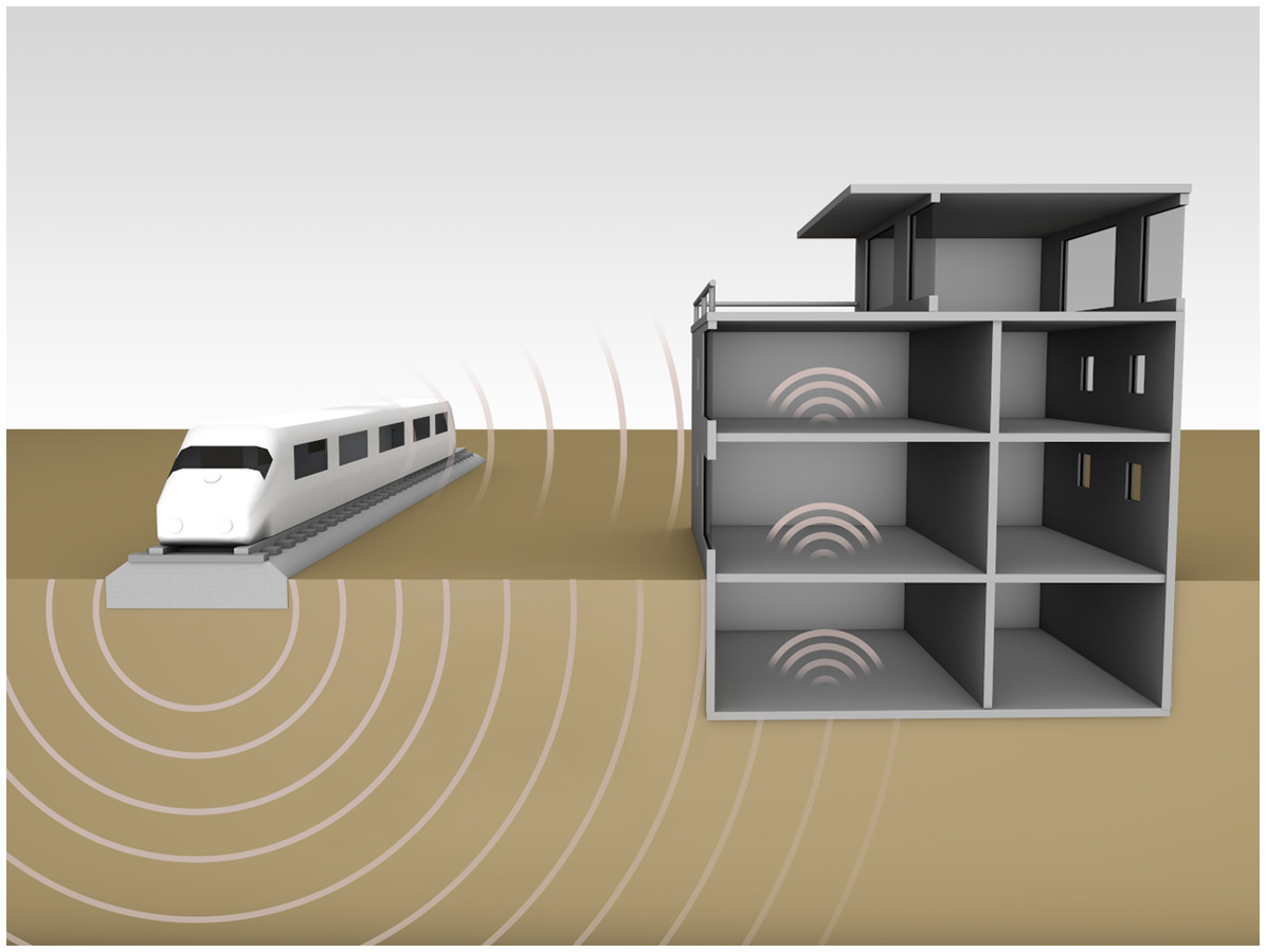
The second source of noise is the transmission of vibrations (=structure-borne noise) caused by trains. These spread through the subsurface and can be reflected at the edges of various ground layers and reach the entire buildings via the foundations. Vibrating ceilings and walls then become the source of secondary airborne noise (Cik and Lercher 2014). This noise can be disturbing at frequencies of . In general, vibrating structural elements emit sound at various frequencies, i.e., across a spectrum. People perceive vibrations with a frequency of [German Institute for Standardization (DIN) 4150-2 (DIN 1999)]. These vibrations can be felt physically and stress people in addition to the audible noise. Therefore, sound control measures must be implemented to prevent or reduce the transmission of structure-borne noise. One suitable way is to introduce components in the track that act as a physical spring. They either insulate the vibration source from its environment (emission insulation) or decouple individual buildings from vibrating subsoil (immission insulation and shielding of buildings). In both cases, the route via which the vibrations spread is cut off.
Emission insulation in ballasted track is done with soft rail pads, under-tie pads, under-ballast mats, or via a floating ballast trough. In the slab track, possible measures are resilient embedded rail systems, resilient base plate pads, light full surface mass spring systems, and heavy mass spring systems on resilient point or strip bearings. The measures are listed with increasing vibration level reduction and increasing costs for each solution [ISO 14837-1 (ISO 2005)].
In Europe, the need for under-ballast mats arose in the 1970s, with the extension of railway lines and legislative steps to protect residences from noise and vibration (Wettschurek et al. 2004). Around the same time, UBM for vibration mitigation were tested in Japan (Yorino 1980). An early and well documented installation of UBM, type Sylomer B851, for the purpose of vibration mitigation was done in 1983 in Munich, Germany. It was laid in a tunnel for urban railway and protected a concert hall from vibrations (Wettschureck et al. 2002). UBMs were also applied with European standard axle loads of about 22.5 t, documented by an example from 1985 (Wettschureck et al. 1999). It was found that UBMs not only reduce vibrations but also increase load distribution and reduce wheel impact to structures or ground. They are used to protect ballast degradation on bridges, protect the bridge structure itself (Kothmayer et al. 2006), reduce secondary airborne noise (Dold and Potocan 2013), and to smooth transition zones (Hunt 1997) (Quirchmair et al. 2022). UBMs prevent sudden changes in stiffness, avoiding high dynamic impacts leading to accelerated track degradation.
For axle loads up to around 22.5 t, UBMs are proven to be suitable for vibration mitigation as well as for an improved track quality. For heavier axle loads of 32.5 t to 36 t, found specifically in heavy-haul applications in the Americas and Australia (up to 40 t), UBMs are used to improve track quality, modify transition zones (Li et al. 2014), and thereby increase the availability. Research at Transportation Technology Center Incorportation (TTCI) has shown that maintenance of concrete deck bridges can be significantly reduced when using UBMs (Akhtar et al. 2008). The intention of this article is to assess the suitability of UBMs for vibration mitigation for heavy-haul axle loads of 325 kN (about 33 t). The reduction of vibrations and secondary airborne noise in an office building located directly next to a railroad track were observed.
A recent research topic for UBM is the evaluation of long-term performance (Dold and Potocan 2013) because many installations have reached a significant age. Other current research on UBMs focused on lab tests of UBM properties to generate input parameters for models (Lima et al. 2018; Kraskiewicz et al. 2021) and simulations (Kumar et al. 2019), toward the research trend of digital twins. Many times, such tests focused on parameters defined by relevant UBM standards [DIN 45673-5 (DIN 2010); EN 17282 (CEN 2020)].
Objective and Scope
The company premises of a Mexican railroad operator contain buildings as well as a depot and a shunting yard, which for a long time had no structural noise protection. Due to the close proximity of an office building to a railroad track, the issues outlined in the “Introduction” section occurred: perceptible vibrations and secondary airborne noise affecting the quality of the workplace. The employees working in the offices described the effects of the neighboring railroad system as “extremely unpleasant” and “disturbing.”
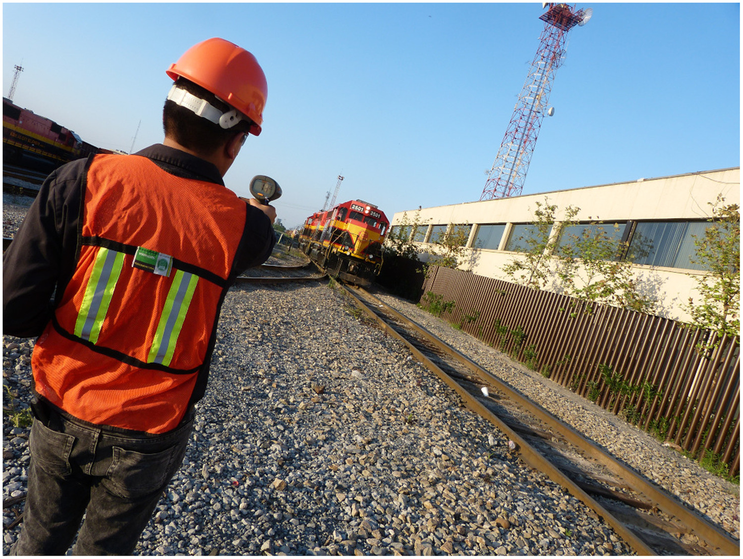
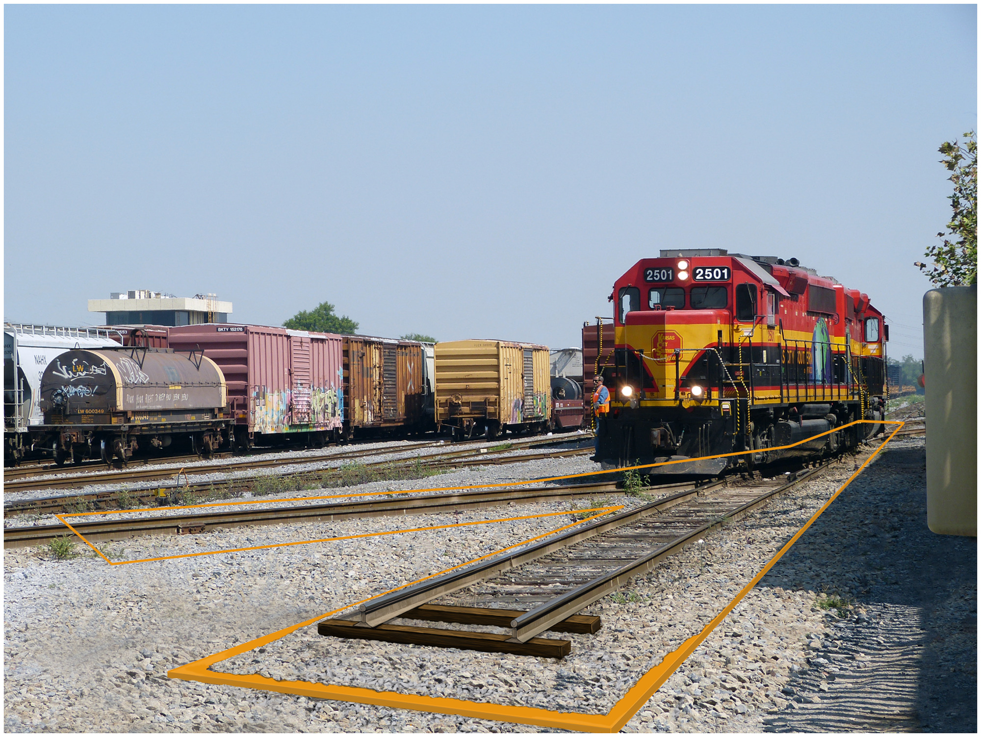
The 100-m-long office building is merely 6 m away from a reserve siding for locomotives (Figs. 2 and 3). The locomotives in question are generally double headings of heavy-duty diesel locomotives with axle loads of up to 33 t. Day-to-day operations involve frequent start-ups and braking, with train speeds of () to (). Due to the low speeds, vibrations also occur at relatively low frequencies of 25 Hz to 40 Hz. People perceive these vibrations as unpleasant and troublesome. By contrast, the structure-borne noise produced by railroads at higher speeds on the open track is usually at its highest in the frequency range of 60 Hz.
The section of track in front of the building features timber ties to which the ribbed base plates and rails are secured with nails. Two railroad switches and a railroad crossing with a covering layer of asphalt exacerbate the occurrence of vibrations. One of the two railroad switches (with a radius of 125 m) is located centrally in front of the building. During an inspection of the railroad installation in March 2017, the consequences of the huge mechanical load during operation were clear to see. The ballast of the superstructure was worn and heavily contaminated.
In light of the extremely unpleasant situation for its employees, the railroad operator contacted Lumietri de México, a sales partner of Getzner Werkstoffe. The objective was to reduce the vibrations and thereby improve workplace quality in the building in the direct vicinity of the railroad system. The specific framework conditions of this renovation with sound protection technology required a customer-specific solution.
Methods and Materials Selection
The customer did not wish to make any structural modifications to the building, and the type of superstructure (ballast bed with ties) had to be retained. The superstructure of the railroad system is therefore to be elastically decoupled from the subsurface. A renovation with UBMs satisfied both technical noise and vibration protection requirements as well as the specific framework conditions.
Vibration Spectrum
In March 2017, before the superstructure was renovated, the vibration intensity of the spectrum (4–200 Hz) was measured. This quantitative characterization of the actual track condition enables the optimum design/choice of the UBMs (“Materials Selection and Properties” section). The same measurements were also done after the renovation to evaluate the achieved vibration.
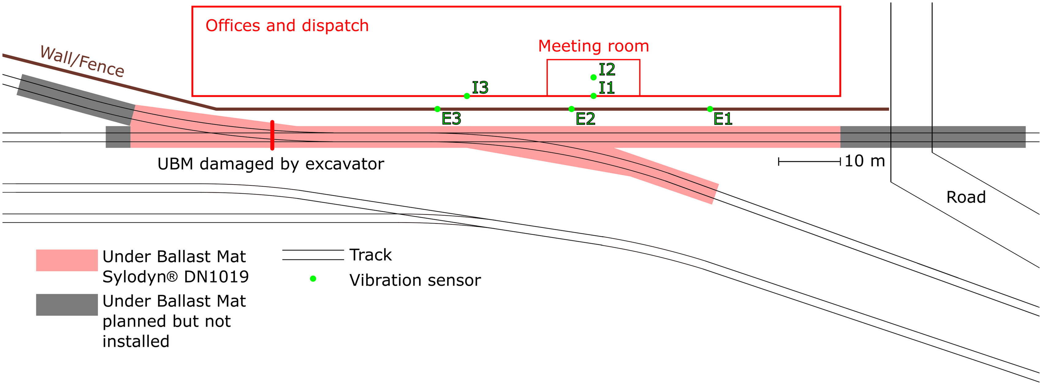
The structure and sequence of each measurement before and after the renovation was the same. In total, six sensors were used, three outside near the track and three inside the building. The external sensors were located on a wall in front of the office building, 4.5 m away from the center of the track [Figs. 3 and 4(a)]. These sensors had a spacing of 22 m. Two sensors were located near the turnout nose (E2 and E3 in Fig. 3); the third sensor was located away from the turnout (E1 in Fig. 3). The external sensors measured the vertical acceleration.
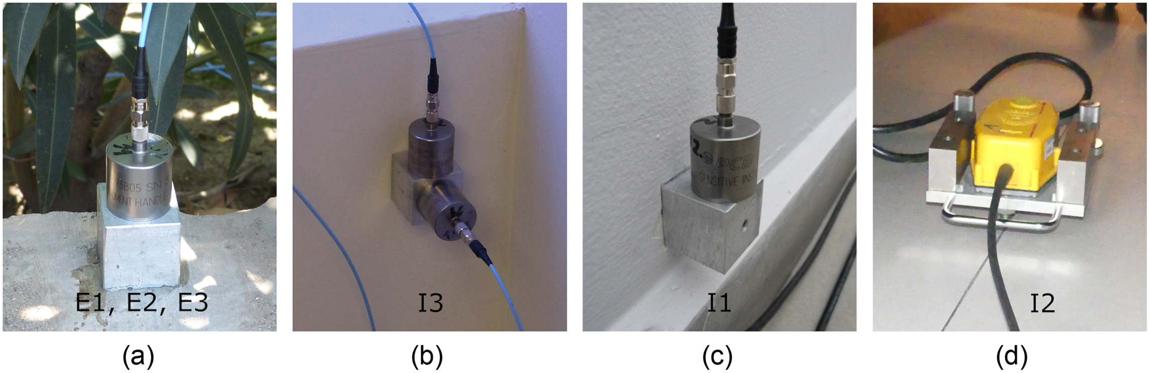
The sensors inside the building were located in two rooms affected by the vibrations. The acceleration was also measured in a vertical direction here. In the first room, on the ground floor, a single sensor was attached to the outside wall [I3 in Figs. 3 and 4(b)]. The wall was 6.75 m away from the center of the track. In the second room, a conference room on the first floor, the measurement was taken with two sensors. One sensor was mounted to the outside wall [I1 in Figs. 3 and 4(c)] and the other sensor was placed on the floor in the center of the room [I2 in Figs. 3 and 4(d)].
As a vibration source, a double heading of diesel locomotives with axle loads between 28 t and 31 t was used. They traveled back and forth at a speed of () to () to simulate normal operation and generate the corresponding vibrations in the surrounding area.
UBMs
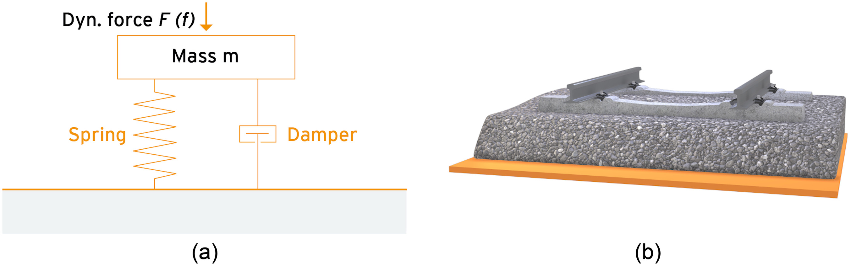
The UBM acts as a combination of a spring and damping element [Fig. 5(a)]: when a train travels over a superstructure seated on a UBM, the UBM reduces the transmission of vibrations to the subsurface and thereby the surrounding area because the spring characteristics of the bearing ensure dynamic decoupling. The effectiveness of the UBM depends on both the bedding modulus and the mechanical loss factor of the material. The degree of transmission characterizes the entire system. It is a function of the properties of the UBM, the frequency f of the periodic load, and the mass . The mass [Fig. 5(a)] is calculated from the dead weight of the superstructure [Fig. 5(b)] and the axle loads of the train.
Materials Selection and Properties
In reality, there is not just one frequency affecting the dynamic load [Fig. 5(a)], but a continuous frequency spectrum. For this reason, the most suitable UBM is one with properties that insulate structure-borne noise with the most troublesome frequencies.
In addition to the vibration spectrum, the axle loads determine the type of UBM. These are particularly high in heavy-haul applications, which makes the maximum permissible rail deflection a central criterion in the selection of a UBM. As such, the Sylodyn DN1019 (Getzner Werkstoffe GmbH, Buers, Austria) used in this project was selected as a relatively rigid polyurethane product.
Sylodyn has very good dynamic properties, as demonstrated by the shape of the characteristic curves:
•
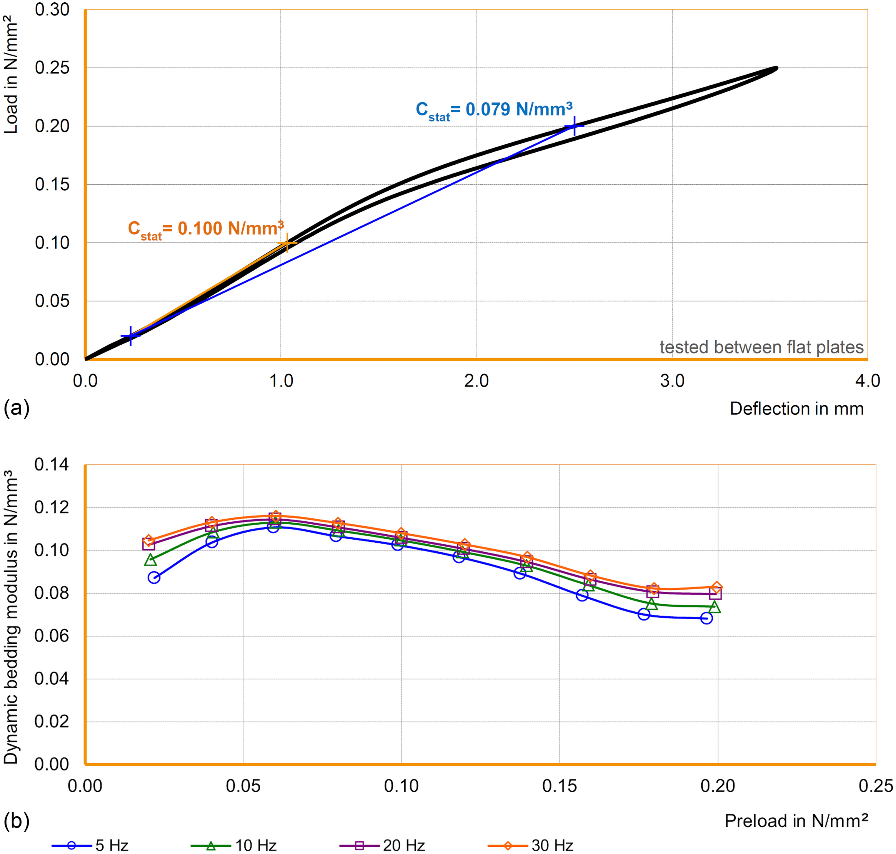
The load-deflection curve [Fig. 6(a)] only depends slightly on whether the test specimen is undergoing loading or unloading. Therefore, the hysteresis between the loading and unloading curve is small. The width of the hysteresis reflects the dynamic behavior because it correlates with the loss factor (which is small in the case of Sylodyn). A UBM with a small loss factor absorbs little energy, which preserves the material especially well in the case of high axle loads or long trains.
•
In the case of small to medium loads the dynamic bedding modulus [Fig. 6(b)] depends, to a small degree, on the load. In the case of larger loads, however [in Fig. 6(b) from ], the bedding modulus decreases as the load increases until it ultimately reaches a minimum. Such UBMs are therefore relatively flexible in the case of loads in the working area (loads near the minimum). This fact results in a low degree of transmission and good insulation of structure-borne noise, at the same time as a high load-bearing capacity and low deflection. By contrast, other materials with good sound insulation, for example, rubber, are often associated with a high deflection. In the case of polyurethanes, the dynamic bedding modulus is slightly dependent on the frequency [Fig. 6(b)] and the preload. This is another advantage of polyurethane materials over alternative materials.
Within the family of foamed polyurethane elastomers, the stiffening of the material under dynamic load in comparison with the static loading case is at its lowest with Sylodyn. In addition to the advantageous shape of the characteristic curve, this property enables an extremely low degree of transmission. Sylodyn achieves the relatively low dynamic stiffening thanks to both the specific cell morphology and the optimized microscopic structure of the polymer matrix. The various raw materials with their characteristic chemical building blocks are harmonized in such a way that the internal friction associated with the deformation and therefore the cause of dynamic stiffening is kept very low.
When the elastomer insulates vibrations, a fleece layer on the UBM protects the foamed polyurethane against the edges and corners of the ballast of the superstructure. Moreover, it reduces the load peaks by increasing the size of the load area. The fleece layer also enables the vehicles onsite during renovation to travel over the UBMs. The structure described here ensures that the function of the Getzner UBMs is guaranteed throughout the entire service life of the superstructure, even under extreme conditions such as standing water or frost. Long-term experience has confirmed the excellent durability of the mats for Sylomer B851 UBMs (Wettschrueck et al. 2002).
Model Calculations
Model calculations are used to estimate technical construction properties such as the base tension of the rails, the load on the ballast, bending moments, and deflection, and thereby optimize the entire system. Models also enable prediction of the effectiveness of the chosen structural measure for vibration insulation.
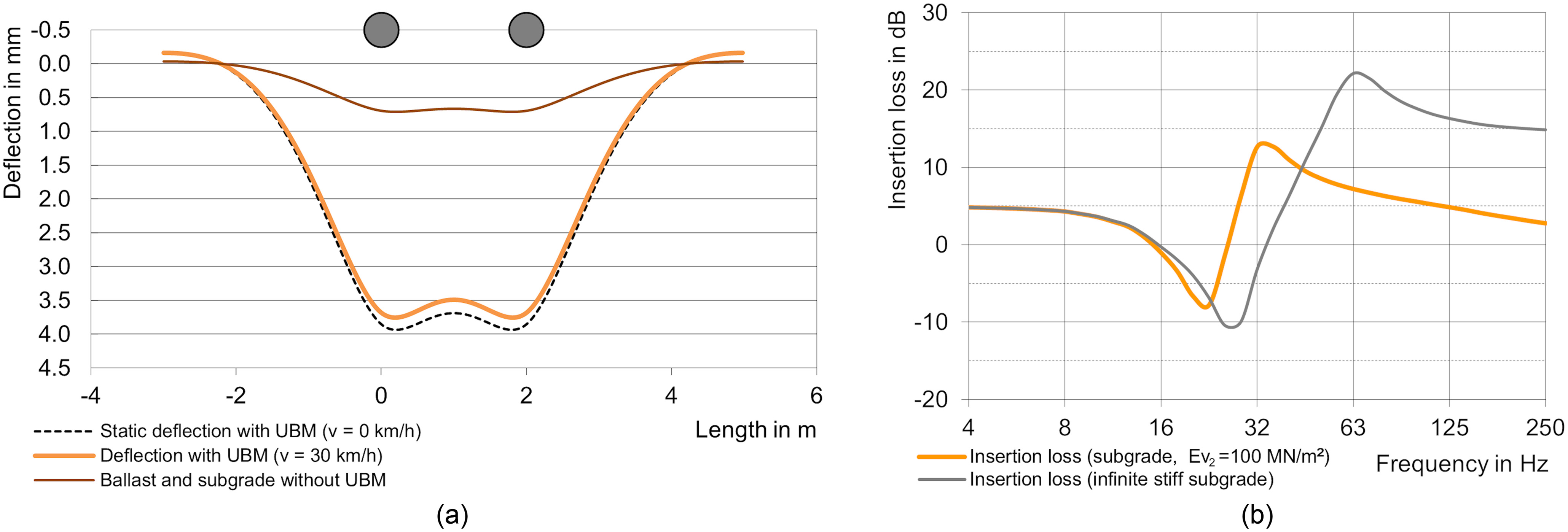
The system was designed on the basis of the Zimmermann model (Fendrich 2007). This simplifies the superstructure and therefore the calculation of characteristic properties. Instead of containing discrete ties, the model is based on an infinitely long tie laid beneath each rail. For this reason, each rail is considered separately from the others. The tie has a fictitious width that is measured in such a way that the bearing surface corresponds to that of half a tie in reality. Physical and technical parameters that characterize the superstructure and the subsurface are included in the calculation of all characteristic properties, for example, the moment of inertia of the rail and the bedding modulus of the UBM (if present). In the dynamic loading case, the bedding modulus of the UBM is multiplied with a material- and speed-dependent stiffening factor. For a train crossing at , the model produced a maximum rail deflection of 3.8 mm [Fig. 7(a)].
The effectiveness of the chosen UBM (Sylodyn DN1019) with regard to the isolation of the vibrations produced by the train is calculated on the basis of the model developed by Wettschureck and Kurze (1985) and Wettschurek et al. (2004). The central property of the UBM included in the model is the dynamic bedding modulus [Fig. 6(b)]. In addition to the UBM, other elastic components such as the rail, tie, and ballast bed are also taken into account. Within the framework of the present model the rigidity of the subsurface is included in the calculation as terminating impedance (Wettschureck and Kurze 1985). This enables differentiation between a very rigid subsurface (e.g., concrete trough in a tunnel) and a more flexible subsurface.
The insertion loss is used to quantify the isolating effect of spring elements [DIN V 45673-4 (DIN 2008)]. The insertion loss records the effect of a minimization measure relative to a reference situation, for example, on the basis of the one-third-octave band spectrum before and after the installation of a UBM or padded ties. Ideally, all other factors affecting the emission of structure-borne noise are kept the same. In general, measurement engineers therefore ensure that the same vehicle, the same speed, the same rail roughness, and so on are used as the basis for the measurements. This is because different insertion loss values are gained in different installation situations with the same spring element. Hence, the insertion loss always depends on the existing overall system including superstructure, subsurface, and so on (Loy 2012; Loy et al. 2018).
The dynamic bedding modulus used to characterize the structural elements is a complex property. It comprises the storage modulus (real part) and the loss modulus (imaginary part) (Ehrenstein 2011). UBMs with a large loss modulus cause a small, relatively flat insertion loss, whereby any negative values in the resonance range are minimal. By contrast, UBMs with an ideal elastic deformation behavior have a small loss modulus. They cause a high insertion loss, i.e., pronounced insulation of the structure-borne noise originating from the train. At the same time resonance phenomena may occur. The insertion loss calculated within the scope of this work reflects these interdependencies: the low hysteresis of the spring characteristic curve [Fig. 6(a)] of the chosen UBM indicates a small loss modulus. As such, both the negative insertion loss (depth of the minimum) and the positive insertion loss (height of the maximum) are pronounced [Fig. 7(b)].
Process Flowchart
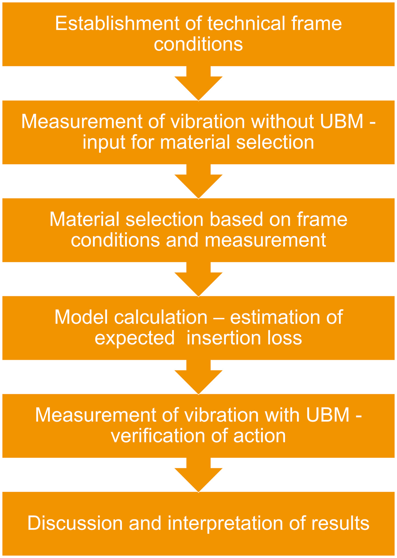
The methodology described in the previous paragraphs for solving a customer’s problem and for creating this case study can be summed up in the flowchart shown in Fig. 8. Most customer requests do not require a vibration measurement before and after renovation because the technical framework conditions are usually sufficient. In special situations such as low speeds and high axle loads, measurements can be very helpful for correct decision making.
Results and Discussion
In November 2017, the Sylodyn DN1019 under-ballast mats were installed: 106 parts delivered in the form of rolls (each 1.5 m wide and 3.5 m long) with a total area of . The individual parts were joined together by means of thermal welding or, in places where there was insufficient space available for this, using adhesive tape.
The UBMs had already been precut at the factory in accordance with the project-specific dimensions. The labeled parts were put together at the construction site according to an installation plan. If the customer wishes to modify individual parts onsite, for example, to create clearances, this is possible at any time by cutting them with a carpet knife.
When carrying out the installation of the UBMs, the railroad switch directly in front of the office building, as well as the timber ties and the ballast were replaced, whereas the rails remained. The new railroad switch, which was already in position, was raised using wooden blocks in order to lay the UBMs. In the area of the track, however, the construction workers laid out the UBMs first so as to subsequently add the ballast and then align the track panel on top.
To insulate the structure-borne noise emitted by trains, Getzner engineers recommend that the railroad installation features UBMs in a radius of approximately 30 m around the building to be protected. In this project, UBMs were not installed in the sections at the railroad crossing and the second railroad switch. UBMs can be subsequently installed in these areas at any time as required.
In October 2018, i.e., after the renovation was complete (Fig. 9), the intensity of the vibrations was measured again. The effectiveness of the measure to protect the office spaces against noise and vibration was evaluated by comparing the measured vibration spectrum with that of the measurement taken before renewal.
Results
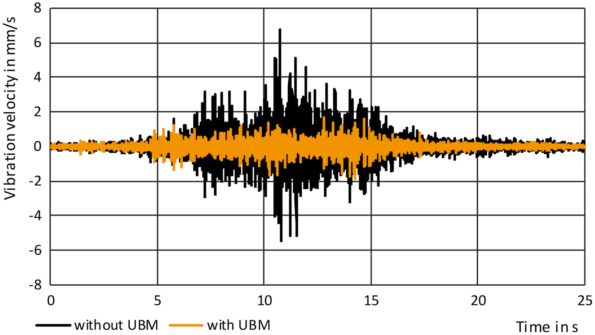
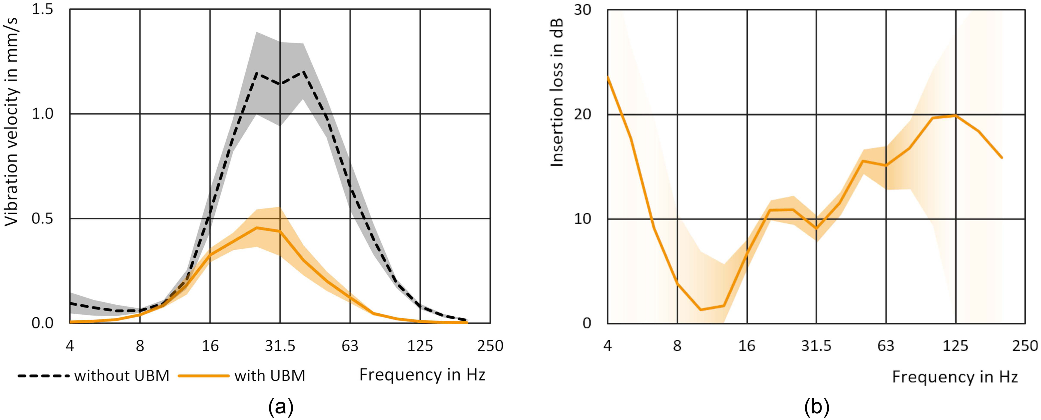
Sixteen crossings of the double heading of diesel locomotives (eight in each direction) in both measurements before and after renewal were recorded and evaluated. These data sets for the vibration velocity as a function of time of the individual sensors (Fig. 10) were used to calculate the vibration velocity as a function of frequency [Fig. 11(a)] for the range of 4 to 200 Hz (fast time evaluation = effective vibration velocity weighted with 0.125 s, maximum hold method). In a further step, the insertion losses for each sensor [Fig. 11(b)] were calculated, which represent the difference between the spectrum without UBMs (before renewal) and the spectrum with UBMs (after renewal) in decibels.
The improvement regarding the vibrations perceptible by people due to the UBMs is characterized by the value. This gives the maximum effective vibration velocity weighted with 0.125 s. The value was calculated in accordance with DIN 4150-2 (DIN 1999).
Discussion
Both the vibration velocities as a function of time (Fig. 10) and the one-third-octave band velocity level spectra [Fig. 11(a)] qualitatively proved the reduction in vibrations due to the UBMs.
The average insertion loss calculated at the three measuring points in front of the building (E1 to E3 in Fig. 3) quantified the effectiveness of the UBMs in insulating structure-borne noise. At 63 Hz, which is where the strongest vibrations typically occur, the UBMs brought an improvement of 15.1 dB or 82%; Fig. 11(b) shows the corresponding curve of one of the three sensors. For reasons including the low speed of travel, the strongest vibrations in this project, however, occurred at lower frequencies [Fig. 11(a)]. With regard to the frequency of 125 Hz, frequencies of 125 Hz and above are relevant for secondary airborne noise, the UBMs actually yielded a reduction of 19.9 dB or 90%—although two of the three measuring points were near the central railroad switch. At frequencies of and , the spread of the insertion loss [Fig. 11(b)] was large because of the low vibration levels after the installation of the UBMs [Fig. 11(a)].
The insertion loss achieved [Fig. 11(b)] indicates commonalities as well as differences compared to the calculated insertion loss [Fig. 7(b)]. The peak is well predicted by the model. If, as in this case, the rigidity of the subsurface is not known, it is advisable to calculate the insertion loss for a range of rigidity levels for the purposes of orientation. Note that the insertion loss derived from the measurements exhibited positive values across the entire frequency range. Furthermore, these values are relatively high, i.e., the isolating effect actually achieved was greater than expected. This could be due to the different structural conditions during the measurements taken before and after renewal. When considering the insertion loss in order to assess the effect of an individual structural component, the boundary conditions are ideally the same. In the case of renovation projects, however—in contrast to investigations made from a purely scientific perspective—it is advisable to implement further structural improvements in addition to the primary renovation measure.
In this case, the old, heavily silted ballast, the ties, and a railroad switch were replaced. On the one hand, this may have reduced the loss modulus of the entire system. On the other hand, it must be assumed that the renovation work has improved the track bed and flatness of the track. Further factors influencing the emission of vibration and structure-borne noise were also different from one another during the two measurements (before versus after the installation of the UBMs). During the measurement after renewal, for example, locomotives with a 10% higher axle load were used. These differences were neglected in the model calculations.
The UBMs reduced the value based on the measurements on the ground floor of the office building by 6 dB or 50%; the average improvement of the values in the building was 44%. This implies a significant reduction in physiologically perceptible vibrations. Employees working in the building have confirmed that this is indeed the case and that the UBMs have improved the quality of their workplace.
UBMs have even more advantages for railroad systems. In addition to their primary use for vibration protection (discussed previously), the increased elasticity of the superstructure brought about by UBMs also leads to better load distribution, keeping the track bed within the permissible limits for longer. UBMs also separate the superstructure from the subsurface. They prevent fine material from the subsurface from entering and contaminating the ballast bed. UBMs therefore prevent mud pumping and improve the drainage of the superstructure. These advantages offered by UBMs reduce maintenance costs for railroad operators and make the laying of UBMs economically attractive.
Conclusion
Protecting people against noise and vibration is gaining in importance. The increasing frequency of trains on railroads requires corresponding protective measures, particularly in areas near residential complexes and places of work. Noise can spread in various ways, including structure-borne noise. This can result in disturbing and harmful levels of secondary airborne noise in buildings near the source, for example. Elastic structural elements can insulate the source of noise from its surrounding area or decouple individual buildings from the vibrating subsurface, thereby reducing secondary airborne noise.
In the case in question, a Mexican railroad company renovated a railroad track for heavy-haul trains using the Sylodyn DN1019 UBM from Getzner Werkstoffe. The under-ballast mat (UBM) acts as a physical spring beneath the ballast bed, reduces vibration, and protects the people working in adjacent buildings against noise and vibrations. This is the first time that UBMs have been used for vibration mitigation in heavy-haul applications in Mexico.
Based on the customer requirements, the appropriate elastic solution, more specifically, the right UBM, for vibration mitigation was chosen by evaluating the boundary conditions and performing model calculations. The solution was validated using vibration measurements before and after the installation.
A comparison of the vibration measurements before and after the installation of the UBMs confirmed the positive impact of this measure to insulate structure-borne noise. At 63 and 125 Hz, the UBMs and the accompanying measures implemented during renovation—including replacing the ballast—produced an insertion loss of 15.1 and 19.9 dB, respectively. The values determined with the sensors inside the building showed an improvement of 44% with regard to the vibrations perceptible by people. The employees working in the building have confirmed the improvement in quality based on their own perceptions.
These values represent a considerable improvement, especially because of the challenging boundary conditions: presence of railroad switches, vibrations occurring at low frequencies, and the installation of UBMs in an area smaller than recommended. Some limitations of the presented study concern a number of unknown parameters, such as subsurface stiffness, exact ballast stiffness, or other components that were changed during track renewal. Another variation was caused by the different types of locomotives used for the test. These variables were either estimated (subsurface) or omitted in the investigation and model calculation. The goal was to show the potential of a simple analytic calculation model.
As well as reducing vibrations, UBMs also improve the long-term quality of the railroad superstructure.
All of the results gathered from the project confirm the suitability of UBMs to provide protection against vibrations on heavy-haul lines. Such protection is not only important for office and residential buildings, but also for buildings containing laboratories or testing equipment, concert halls, hospitals, and historic buildings. When laid on railroad bridges, UBMs can reduce the emission of secondary airborne noise.
This study of technical noise protection renovation measures have quantitatively proven both their acoustic and economic benefits. This helps acceptance among system operators and developers.
Recommendations
This study showed that the existing simple analytic calculation models can be used to calculate a UBM for vibration mitigation in heavy-haul applications. The calculation model was validated by Wettschureck (Wettschureck and Kurze 1985) for relatively low axle loads (about 175 kN) for urban rapid transit. Yet with some additional considerations, the same model was applied to heavy hauls with axle loads of 325 kN. Considering the following points, good results can be achieved when choosing a vibration mitigation measure:
•
Boundary conditions such as technical and economic feasibility need to be considered.
•
Relevant inputs for the model are vehicle properties (axle load, axle spacing, and unsprung mass of the vehicle), superstructure properties (rail, rail pad, sleeper, under tie pad, ballast height, UBM, and subsurface), and operating conditions (train speed).
•
When doing model calculations, unknown parameters (very often subsurface stiffness) can be addressed by doing multiple calculations with varying parameters. The different outcomes are then compared and evaluated.
•
Rail deflection should be within defined limits. Softer materials with higher vibration mitigation performance can cause increased rail deflections, especially in the case of heavy axle loads. A material should be dynamically soft in the working range. Polyurethane UBMs show such behavior [Fig. 6(b)].
•
The excitation frequency and the resonance frequency of the system need to be considered. In the presented case, the train speeds were low, resulting in low excitation frequencies.
Data Availability Statement
All vibration data and information on the software used for evaluation are available from the corresponding author upon reasonable request. All vibration data were recorded by the authors.
Acknowledgments
The authors would like to thank the industrial and scientific project partners who provided their support, namely Lumietri de México S.A. de C.V., Getzner Werkstoffe GmbH, and the University of Innsbruck-Department of Infrastructure, Unit of Intelligent Transport Systems.
References
Akhtar, M., D. Otter, and B. Doe. 2008. Stress-state reduction in concrete bridges. Pueblo, CO: Transportation Technology Center.
Buratti, C., E. Moretti, and M. Vergoni. 2010. “Sound insulation performances of windows: Evaluation of the influence of different traffic noise spectra in laboratory and field measurement.” In Proc., 17th Int. Congress on Sound and Vibration 2010. Cairo, Egypt: International Institute of Acoustics and Vibration.
CEN (European Committee for Standardization). 2020. Railway applications: Infrastructure: Under ballast mats. EN 17282. Brussels, Belgium: CEN.
Cik, M., and P. Lercher. 2014. Ground-borne vibrations, sounds and secondary airborne sounds from tramways: A psychoacoustic evaluation including health aspects. Melbourne, Australia: Inter-Noise.
DIN (Deutsches Institut für Normung; German Institute for Standardization). 1995. Vibration measurement associated with railway traffic systems: Part 2: Evaluation method. DIN 45672-2. Berlin: DIN.
DIN (Deutsches Institut für Normung; German Institute for Standardization). 1999. Structural vibration, Part 2: Human exposure to vibration in buildings. DIN 4150-2. Berlin: DIN.
DIN (Deutsches Institut für Normung; German Institute for Standardization). 2008. Mechanical vibration: Resilient elements used in railway tracks: Part 4: Analytical evaluation of insertion loss of mounted track systems. DIN V 45673-4. Berlin: DIN.
DIN (Deutsches Institut für Normung; German Institute for Standardization). 2010. Mechanical vibration—Resilient elements used in railway tracks: Part 5: Laboratory test procedures for under-ballast mats. DIN 45673-5. Berlin: DIN.
DIN (Deutsches Institut für Normung; German Institute for Standardization). 2012a. Soil: Testing procedures and testing equipment: Plate load test. DIN 18134. Berlin: DIN.
DIN (Deutsches Institut für Normung; German Institute for Standardization). 2012b. Vibration measurement associated with railway traffic systems: Part 1: Measuring method for vibration. DIN 45672-1. Berlin: DIN.
Dold, M., and S. Potocan. 2013. “Long-term behavior of Sylomer ballast mats.” Rail Technol. Rev. 53 (Mar): 39–41.
Ehrenstein, G. 2011. Polymer Werkstoffe. Struktur, Eigenschaften, Anwendung [Polymer materials. Structure, properties, application]. Munich, Germany: Carl-Hanser-Verlag.
Fendrich, L. 2007. Handbuch Eisenbahninfrastruktur [Railroad infrastructure manual]. Berlin: Springer.
Hunt, H. 1997. “Settlement of railway track near bridge abutments. (Third paper in young railway engineer of the year (1996) award).” Proc. Inst. Civ. Eng. Transp. 123 (1): 68–73. https://doi.org/10.1680/itran.1997.29182.
ISO. 2005. Mechanical vibration—Ground-borne noise and vibration arising from rail systems—Part 1: General guidance. ISO 14837-1. Geneva: ISO.
Kothmayer, H., M. Mautner, and M. Reiterer. 2006. “Remediation of an arched bridge using a mass-and-spring system.” Rail Technol. Rev. 4 (46): 6–12.
Kraskiewicz, C., A. Zbiciak, K. Wasilewski, and A. Al Sabouni-Zawadzka. 2021. “Laboratory tests and analyses of the level of vibration.” MDPI Mater 14 (2): 313. https://doi.org/10.3390/ma14020313.
Kumar, N., B. Suhr, S. Marschnig, P. Dietmaier, C. Marte, and K. Six. 2019. “Micro-mechanical investigation of railway ballast behavior under cyclic loading in a box test using DEM: Effects of elastic layers and ballast types.” Granular Matter 21 (Oct): 106. https://doi.org/10.1007/s10035-019-0956-9.
Li, D., R. Jimenez, J. Baillargeon, and L. Maal. 2014. Long-term performance of bridge approach remedies implemented at western mega site. Washington, DC: Transportation Technology Center.
Lima, A., M. Dersch, Y. Qian, E. Tutumluer, and J. Edwards. 2018. “Laboratory fatigue performance of under-ballast mats under varying loads and support conditions.” Proc. Inst. Mech. Eng., Part F: J. Rail Rapid Transit. 233 (6). https://doi.org/10.1177/0954409718795920.
Loy, H. 2012. “Körperschall-/Erschütterungsschutz durch besohlte Schwellen - Wirkung und Grenzen [Mitigation of structure-borne noise and vibrations using padded ties. Effect and limits].” Eisenbahntechnische Rundsch. 12 (Dec): 66–70.
Loy, H., A. Augustin, and L. Tschann. 2018. “Reduction of vibration emissions and secondary airborne noise with under-sleeper pads—Effectiveness and experiences.” In Vol. 139 of Noise and vibration mitigation for rail transportation systems. Notes on numerical fluid mechanics and multidisciplinary design. Cham, Switzerland: Springer.
Maclachlan, L., K. Waye, and E. Pedersen. 2017. “Exploring perception of vibrations from rail: An interview study.” Int. J. Environ. Res. Public Health 14 (11): 1303. https://doi.org/10.3390/ijerph14111303.
Ouakka, S., O. Verlinden, and G. Kouroussis. 2022. “Railway ground vibration and mitigation measures: Benchmark of best practices.” Railway Eng. Sci. 30 (1): 1–22. https://doi.org/10.1007/s40534-021-00264-9.
Quirchmair, M., S. Werner, B. Burgherr, and H. Loy. 2022. “Sittertobel renovation improves track forces.” Railway Gezette Int. (May): 26–30.
Schlattjan, J., G. Eberwein, R. Nehring, I. Scheler, and J. Witten. 2014. Gesundheitliche Auswirkungen von Bahnlärm [Health impact of railway noise]. Mainz, Germany: Ministry of Environment Rhineland-Palatine, Ministry of Social Affairs Hessen, Ministry of Environment North Rhine-Westphalia.
Wettschrueck, R. G., M. Heim, and M. Tecklenburg. 2002. “Long-term properties of Sylomer ballast mats installed in the rapid transit railway tunnel near the Philharmonic Hall of Munich.” Rail Eng. Int. (4): 6–11.
Wettschureck, R., F. Breuer, M. Tecklenburg, and H. Widmann. 1999. “Installation of highly effective vibration mitigation measures in a railway tunnel in Cologne.” Rail Eng. Int. (4): 12–16.
Wettschureck, R., and U. Kurze. 1985. “Einfügedämmaß von Unterschottermatten” [Insertion loss of ballast mats]. Acustica 58: 177–182.
Wettschurek, R., G. Hauck, R. Diehl, and L. Willenbrink. 2004. “Geräusche und Erschüterungen aus dem Schienenverkehr” [Noise and vibration from rail traffic]. In Taschenbuch der Technischen Akustik [Handbook of engineering acoustics], edited by G. Müller and M. Möser, 483–584. Berlin: Springer.
Yorino, T. 1980. “Environmental preservation and the Shinkansen.” In Proc., IIASA Conf., the Shinkansen High-Speed Rail Network of Japan, edited by T. R. Straszak, 171–190. Oxford, UK: Pergamon.
Information & Authors
Information
Published In

Practice Periodical on Structural Design and Construction
Volume 28 • Issue 4 • November 2023
Copyright
This work is made available under the terms of the Creative Commons Attribution 4.0 International license, https://creativecommons.org/licenses/by/4.0/.
History
Received: Sep 9, 2022
Accepted: Feb 28, 2023
Published online: Aug 4, 2023
Published in print: Nov 1, 2023
Discussion open until: Jan 4, 2024
ASCE Technical Topics:
- Buildings
- Business management
- Continuum mechanics
- Dynamics (solid mechanics)
- Engineering mechanics
- Environmental engineering
- Health hazards
- Infrastructure
- Materials engineering
- Mitigation and remediation
- Motion (dynamics)
- Noise pollution
- Pollution
- Practice and Profession
- Public administration
- Public health and safety
- Rail transportation
- Railroad ballast
- Railroad tracks
- Solid mechanics
- Structural engineering
- Structures (by type)
- Transportation engineering
- Vibration
Authors
Metrics & Citations
Metrics
Citations
Download citation
If you have the appropriate software installed, you can download article citation data to the citation manager of your choice. Simply select your manager software from the list below and click Download.