Underperformance Assessment Framework for Bioinfiltration Systems
Publication: Journal of Sustainable Water in the Built Environment
Volume 8, Issue 3
Abstract
Stormwater management practices (SMPs) are increasingly being implemented in urban environments to provide water quality and quantity benefits to municipalities. Bioinfiltration systems (e.g., rain gardens) are a common type of SMP that rely on the infiltration of stormwater into the soil to capture and filter stormwater and make water available to plants. Most municipalities require that the maximum time for the ponded water to infiltrate (drain-down time) does not exceed 24–72 h after rainfall. If there is sustained ponding beyond this time period, the bioinfiltration system is considered to be underperforming. Management of such underperforming systems often involves substantial and costly restoration efforts (e.g., reconstruction, soil replacement), forfeiting infiltration benefits to pivot to a bioretention or other SMP approach, or even in some cases abandoning the SMP. A systematic forensic investigation to identify the specific cause(s) of underperformance may allow for more targeted, effective, and economical rehabilitation of the underperforming SMP. In this study, an underperformance assessment framework (UAF) was developed and applied to five underperforming bioinfiltration sites to identify the causes of extended ponding and inadequate water quantity removal relative to design standards. Once likely causes of underperformance were identified, targeted rehabilitation techniques were recommended to restore system performance. Through the use of this comprehensive and systematic tool, isolated SMP components can be identified and rehabilitated, thus avoiding the entire system overhaul, minimizing restoration costs, and avoiding the recurrence of similar issues. Future benefits resulting from the increased knowledge of bioinfiltration systems gained by using this tool include improvements to system design and maintenance, thus ensuring the sustainability and resiliency of urban SMPs.
Introduction
In recent decades, advances in urban stormwater management have altered the urban landscape as communities around the world move toward implementing green stormwater management practices (SMPs) (Roy-Poirier et al. 2010). SMPs can mitigate challenges associated with urban stormwater by improving the quality of urban runoff and reducing urban flood pulses (Scholes et al. 2008; LeFevre et al. 2015; Jarden et al. 2016). Over time scales beyond a single event, SMPs may help reduce hydrologic flashiness by extending baseflow recession (Bell et al. 2016). In the face of increased urbanization (Debbage et al. 2017), SMPs aid municipalities and stormwater managers in meeting federal regulations (Dietz 2007; Zimmer et al. 2007). While there are many benefits associated with SMPs, the relatively recent development of this type of infrastructure faces implementation challenges. The first generation of SMPs illuminated the need for a deeper understanding of maintenance and inspections to ensure long-term performance and infrastructure sustainability (Lindsey et al. 1992; Blecken et al. 2017; Flynn et al. 2012; Houle et al. 2013).
Bioinfiltration systems (e.g., rain gardens) are a common type of SMP that rely on infiltration to capture and filter stormwater. In the United States, SMPs must “ensure adequate long-term operation and maintenance of controls” (USEPA 2020), which for bioinfiltration systems includes continuing to adequately and consistently infiltrate stormwater adherent to regulatory-defined rates. However, the performance of bioinfiltration SMPs over time can be negatively impacted by the accumulation of sediments, pollutants and litter, erosive flood pulses, poor design, problematic construction practices, or inadequate maintenance (DelGrosso et al. 2019). According to PADEP and Bureau of Watershed Management (2006), the primary causes of reduced performance for stormwater infiltration SMPs are poor construction techniques, inadequate design, a lack of soil stabilization, inadequate pretreatment, and inadequate maintenance. If left unchecked or unmaintained, infiltration SMPs can become susceptible to underperformance or even failure (DelGrosso et al. 2019).
As SMPs continue to age and their use continues to expand, it is necessary to define and create a framework for systematically identifying specific causes of underperformance in bioinfiltration systems. Unraveling the effects of multiple drivers influencing SMP performance is complex. Due to the complexity of these systems, a diagnostic procedure is required to establish the causes of underperformance. By taking an analytical systematic approach, not only can the problems affecting the SMP be identified, but the drivers resulting in performance issues can also be isolated and addressed. Addressing both the causes and effects of underperformance is critical to facilitating the system’s ability to function sustainably. This manuscript describes a diagnostic framework for the systematic analysis of underperforming bioinfiltration basins, referred to as the underperformance assessment framework (UAF). This methodology is then applied to five different SMPs across three different project locations as case studies.
Background
Defining Underperformance
While SMP performance has been evaluated in regards to a variety of metrics including nutrient and metals removal, solids removal, bacteria retention, runoff volume retention and reduction, peak flow reduction, delay in flow peak, and groundwater mounding (Ahiablame et al. 2012; Hatt et al. 2007; Davis 2008; Catalano de Sousa et al. 2016; Jefferson et al. 2017; Erickson et al. 2018; William et al. 2019), government compliance standards require SMPs to be evaluated by drain-down times, infiltration rates, and maintenance frequency (PADEP and Bureau of Watershed Management 2006; PWD 2020; Minnesota Pollution Control Agency and Minnesota Stormwater Steering Committee 2008; Wadzuk et al. 2021). Here, we define underperformance in line with government compliance standards, as the inability of an SMP to effectively infiltrate stormwater, resulting in consistently ponded water or insufficient drainage.
Sustained ponding may be the result of inadequate infiltration due to factors such as a restrictive soil layer or high groundwater. Abnormally high inflow rates may also contribute to inadequate drain-down times. A restrictive layer at the surface can result from compaction, high inflow of fine material which may result from nearby construction, or accumulation of fines, sediment, or mulch over time (i.e., clogging) (Asleson et al. 2009; Brown and Hunt 2010; Emerson et al. 2010; Olson et al. 2013; Reddi et al. 2000). An undetected restrictive layer under the bioinfiltration systems could also impede infiltration. Insufficient or inadequate maintenance practices often exacerbate these conditions leading to the low performance of such systems. Untangling the complex, sometimes overlapping drivers of underperformance is challenging but necessary for extending the lifespan of sustainable infrastructure.
Soil
Bioinfiltration systems rely on the ability of the media and underlying soil to effectively infiltrate water over time. Thus, subsurface investigations and characterization of the basin media and underlying soils are critical to the design. Field infiltration testing typically is a required component of design and construction. However, results from commonly used spot-infiltration, or in-situ, test methods can be highly variable (Ebrahimian et al. 2020) and are affected not only by variability in soil properties but also by factors such as water temperature (Braga et al. 2007; Emerson and Traver 2008; Jaynes 1990), macropores from plant roots and macroorganisms (e.g., worms) (Le Coustumer et al. 2009; Fassman-Beck et al. 2015), and water quality. Variations in soil texture, plasticity, and dry density significantly impact the saturated hydraulic conductivity () and the ability to store and drain water (e.g., field capacity). While soil properties have been thoroughly studied and related to infiltration in the literature, they can be difficult to measure and confirm in the field due to the destructive and laborious nature of soil sampling and laboratory testing.
Multiple projects have shown the high cost associated with overcoming initial soil issues due to construction (Shafique and Kim 2017), resulting in a range of programs targeted at improving SMP construction (Lai et al. 2006; Jayasooriya and Ng 2014). Common issues arising during construction include soil compaction due to heavy equipment or foot traffic, improper or heterogeneous soil placement, or use of inappropriate media (e.g., Pitt et al. 2008; Brown and Hunt 2010). Compaction or clogging of all bioinfiltration systems soil during or after construction can cause significant reductions in (e.g., by orders of magnitude), resulting in infiltration rates below regulatory requirements (e.g., ; PWD 2020).
Surface Dynamics
There is a growing interest in understanding and quantifying the impact of sediment deposition on SMP performance (Siriwardene et al. 2007; Jenkins et al. 2010; Le Coustumer et al. 2012). Bioinfiltration systems over time can be heavily impacted by erosion or deposition of significant amounts of sediment (USEPA 1999; Delgrosso et al. 2019). While large flows may introduce litter that requires additional maintenance, both small and large flows transport fine-grained particles. Many studies have shown the ability of SMPs to remove total suspended solids (TSS) from stormwater flows (Shafiquea and Kim 2017). Fine particles within the TSS have the potential to clog the SMP media pores, reducing the of the soil (Langergraber et al. 2003; Asleson et al. 2009; Virahsawmy et al. 2014).
Inversely, erosion when present has adverse impacts on SMP performance. Surface destabilization, mulch removal, bare spots, cave-ins, and associated structural deficiencies are all potential negative effects of erosion on bioinfiltration systems (DelGrosso et al. 2019). The prevalence of these issues and their impact on performance has made erosion a key indicator in SMP inspections and maintenance (Environmental Services Division, Dept. of Environmental Resources, and The Prince George’s County, Maryland 2007; WSU and PSP 2012; Portland Bureau of Environmental Services 2016; DPWES and MSMD 2017).
Inflow
Two potential issues arise associated with inflow parameters: inadequate/excessive flow or excessive sediments. Excessive inflows can be highly erosive (DelGrosso et al. 2019). Excessive influent TSS concentrations entering SMP systems have been found to adversely affect their long-term performance (William et al. 2019). Excessive sedimentation impacts the surface dynamics, and ultimately performance, of the SMP, as discussed. Often, issues due to inflows occur during construction activities when the system is temporally altered from the design to facilitate construction or when there is substantial earthwork in the area (Shafique and Kim 2017; DelGrosso et al. 2019). Subsurface inflow from high groundwater tables may also affect infiltration performance (Zhang and Chui 2019).
Underdrain
Bioinfiltration sites rely on infiltration into the underlying soils below the amended media. Regulatory agencies often require that underdrains be provided for bioinfiltration and bioretention SMPs. These underdrains may be capped to facilitate infiltration into native soils (e.g., PWD 2020). However, if underperformance is observed, drilling an orifice into the underdrain cap or uncapping of the underdrain may be an initial attempt to facilitate faster drain down if the issue is due to impeded infiltration into the native soil. Underdrains may be required in SMPs when underlying soils have low [e.g., ()] (Sileshi et al. 2018). Utilizing the underdrain essentially allows the bioinfiltration system to function more similarly to a bioretention system if needed.
Underdrain pipes are used to collect water from the bottom of SMPs and deliver the collected water to a sewer system or to a river system during storm events (Guo 2012; Hunt et al. 2012). One type of design has an underdrain pipe slightly sloped toward the outlet of the SMP (i.e., entrance elevation is lower) to facilitate debris removal utilizing gravity. Not all underdrains perform equally. The underdrain pipe can have various pressure heads at the outlet and from water in the rock bed storage and may vary in slope, perforation, or pipe size. Such differences increase the variability of performance of the underdrain pipe and pose challenges to analyses (Tu and Traver 2019). It is difficult to accurately size underdrains to obtain desired flow capacities without inhibiting the use of the natural infiltration of the underlying soils (Hunt and Lord 2006; Sileshi et al. 2018). In addition, the sand/stone filter layer and geotextile fabric commonly used around the underdrains may be susceptible to clogging due to sediments and biomass (Bouwer 2002). If the underdrain becomes clogged, it may need to be cleaned out or replaced. Additional actions may include installing longer underdrains to increase surface area or adding a second underdrain to provide redundancy.
Methods
The SMP diagnostic approach presented herein, referred to as the UAF, consists of a combination of methods including field data and observations, laboratory testing, and analyses. The relationship between these method components is shown in Fig. 1. Field measurements and soil samples are collected and then subsequently analyzed in the laboratory. Specific field investigations may include flow monitoring, drainage area analysis, spot-infiltration tests, sediment collection, surveying, test pits, and soil core sampling. In the laboratory, soil samples typically would be analyzed for particle-size distribution, plasticity, organic content, and dry density. However, field and laboratory investigations may be tailored to the specific bioinfiltration site and observed underperformance characteristics or limited by site access and/or time and labor constraints. All field and laboratory data are then analyzed numerically, temporally, and spatially. As necessary, spatial analysis of field and laboratory data is georeferenced, including site features and results related to soil properties, slopes, elevation changes, and ponded areas.
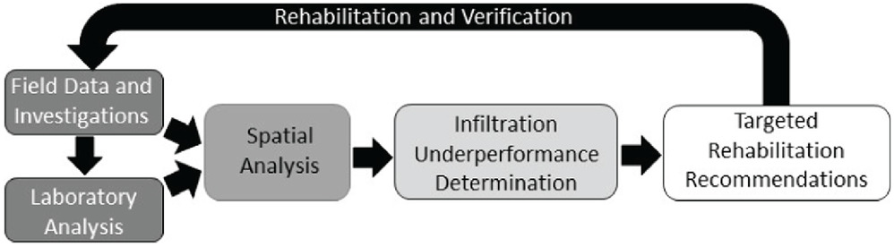
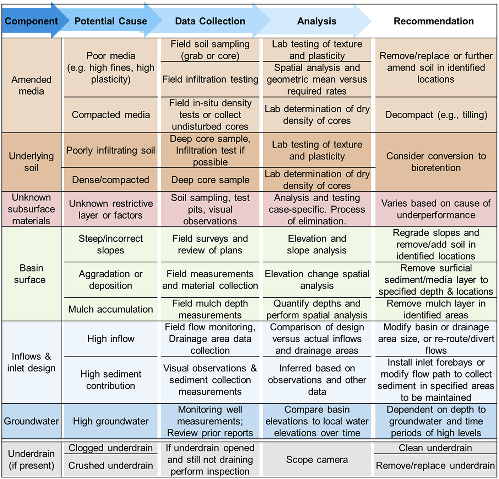
This holistic and systematic approach to SMP forensic analysis allows for the identification of a specific component’s contribution to the overall underperformance of the SMP. Integrating a range of data and methods to test several possible drivers of bioinfiltration system underperformance through the UAF allows for targeted rehabilitation recommendations based on the identified causes. Examples of such recommendations are provided in Fig. 2. In cases where the scope of data collection methods that can be applied during the forensic investigation is limited by budget or project constraints, the following data collection methods can be prioritized as the most essential: (1) field infiltration testing, (2) test pits and visual observation of soils, (3) visual inspection of inflow and sediment influx, and (4) postconstruction inspection for comparison to design plans. Infiltration tests can identify if the amended media is the source of the underperformance, which is further supported by soil sampling. Test pits show if the underlying soil is the cause of underperformance and can reveal evidence of high groundwater. Visual inspection of inflows can illuminate if further testing is warranted. However, a comparison of postconstruction inspection with design plans can highlight potential areas of risk for underperformance. These tasks will not provide a full analysis of the SMP but can narrow the focus of the forensic analysis to one set of measurements to minimize data collection.
The described framework was applied to five different bioinfiltration systems at three project sites in urban and suburban locations spanning two states.
Case Studies 1 and 2: Two Bioinfiltration SMPs in Philadelphia, Pennsylvania
Description of Sites 1 and 2
This forensic framework was applied to two underperforming bioinfiltration SMPs that had been constructed as part of the I-95 Girard Avenue Interchange Project in Philadelphia, Pennsylvania. The two bioinfiltration systems, herein referred to as Sites 1 and 2, were constructed in 2015 by the Pennsylvania Department of Transportation (PennDOT) to provide stormwater management for runoff associated with the highway. Within the first two years of operation, the SMPs were identified as underperforming due to the inability to drain within 24–72 h after a rain event per PennDOT, PWD, and Pennsylvania Department of the Environment (PADEP) standards at the time of design and study. To determine the cause(s) of underperformance, a forensic investigation was conducted by Villanova University UAF.
The two bioinfiltration systems are adjacent to one another and both manage runoff from the elevated highway deck abutting the systems. Site 1 has one inlet pipe and was designed for a drainage area of 0.87 acres, whereas Site 2 has two inlet pipes and was designed for a drainage area of 0.8 acres; both correspond to a loading ratio (drainage area to SMP area) and have a 100% impervious drainage area not including the rain gardens themselves. Both systems include 8-in. underdrains, and each is connected to the Philadelphia combined sewer system via a concrete outlet structure equipped with weirs. The underdrains in these systems were initially capped but were later opened in an attempt to improve SMP performance after issues surrounding sustained ponding had been observed. The layer of infiltration soil media at both sites was 0.6 m (2 ft) of imported loamy sand or sandy loam. Infiltration rates were measured for the amended soil right after construction; the average values reported by the contractor were to () for Site 1 and Site 2, respectively, which were well within recommended ranges by the PADEP (). From subsurface investigations prior to construction, the underlying subgrade was generally characterized as sandy loam and silt loam. Inflow enters both systems perpendicularly to the main axis and general flow pattern.
Data Collection for Sites 1 and 2
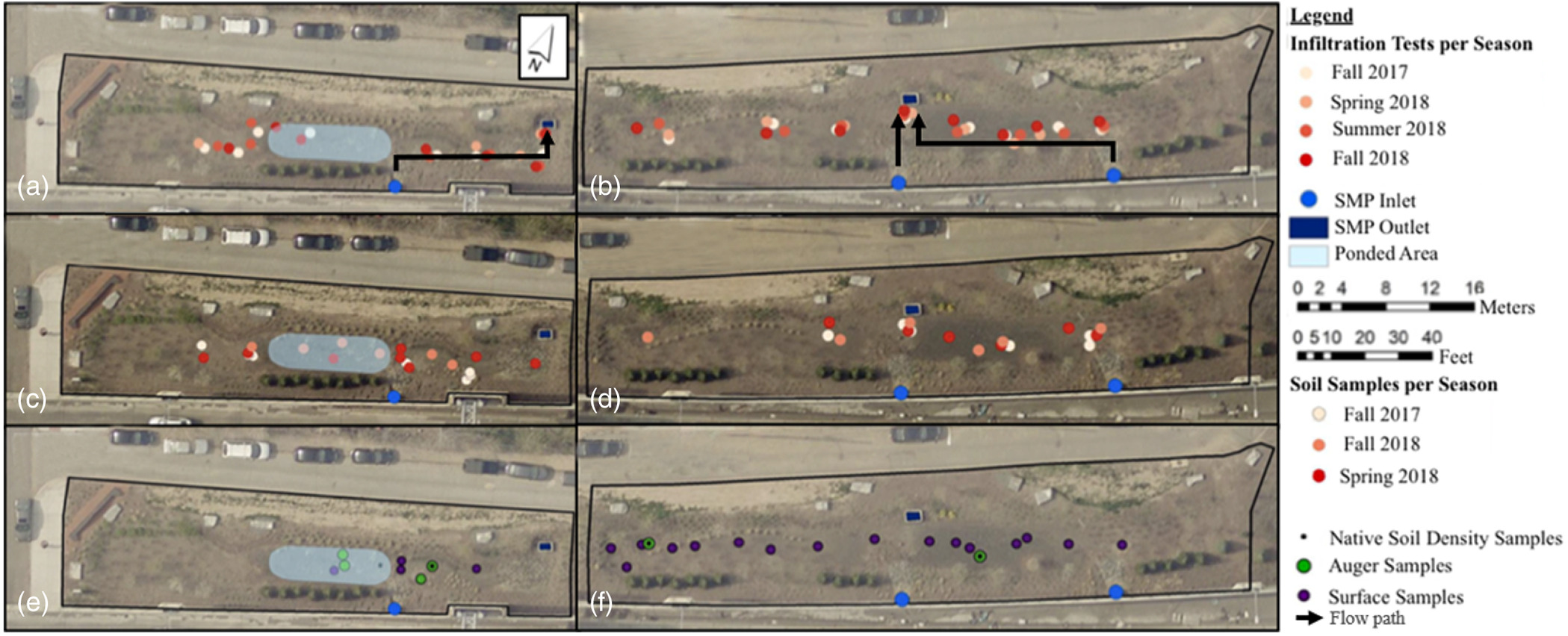
As part of the forensic investigation, spot-infiltration tests were conducted at recurring locations for the two sites during fall 2017, spring 2018, summer 2018, and fall 2018 to evaluate seasonal impacts on infiltration. Saturo DualHead infiltrometers (METER Group 2017) were used to measure at five to eight different locations at each site during each test season. Test locations were georeferenced in ArcGIS and are shown in Figs. 3(a and b). Field results from the infiltration tests were adjusted for changes in water viscosity with temperature and corrected to a temperature of 20°C () to allow for data comparison.
Values of from field infiltration tests typically are log-normally distributed, supporting the use of the geometric mean as the overall representative as long as a sufficient number of tests have been performed (Ebrahimian et al. 2020). Press (2019) tested eight different bioinfiltration/bioretention sites (varying in size from 62 to ) using single-ring infiltrometers and compared the results to observed ponding recession rates. For all of the sites, the geometric mean based on five to six infiltration tests provided a value in agreement with the recession rates (i.e., values within 5% to 70% difference from the recession rate, with an average difference of 37%). Thus, in this study, the inclusion of five to eight infiltration locations for Sites 1 and 2 was considered sufficient to use the geometric mean to determine a representative value for the site.
Soil core samples of the soil media were collected in fall 2017, spring 2018, and fall 2018 in recurring locations beneath the mulch layer according to ASTM D2937 ASTM (2017a). Samples were collected in 15.24 cm long (6 in.) segments with a coring device using 5.08 cm (2 in.) diameter, plastic sleeves, and plastic end caps (Part No. 404.21, AMS, American Falls, Idaho). Typically, two to three samples were taken in line vertically at a single location, giving a total depth of 30.48 to 45.72 cm (12 to 18 in.). Deeper grab samples of the media were obtained when possible. The locations of the media core samples are shown in Figs. 3(c and d). Two deep samples from the in-situ soil underlying the amended media in each site also were taken in August 2018 using a hand auger. At Site 1, samples of the underlying soil were taken to a depth of 122 cm (48 in.) from the ground surface; in Site 2, samples were taken to a depth of 94 cm (37 in.) from the ground surface. Loose surficial soil samples were also collected using a hand trowel in each bioinfiltration site. Locations of auger and surface samples are shown in Figs. 3(e and f).
All soil samples were tested and characterized in the laboratory to determine soil properties and conditions related to underperformance. The methods utilized in the soils testing program are described in detail in Smith et al. (2021). Soils were analyzed for particle-size distribution (ASTM 2017b, d), dry density, water content (ASTM 2019), organic content (ASTM 2020), and plasticity (ASTM 2017c). Soils were classified using both the Unified Soil Classification System (USCS) and the USDA classification systems.
At both Sites 1 and 2, a postconstruction survey was conducted by PennDOT contractors approximately one-year postconstruction, and a second survey was conducted by Villanova nearly two years postconstruction as part of the UAF investigation. In 2018, a topographic survey of Sites 1 and 2 was completed and used to generate a 0.305 m by 0.305 m (1 ft by 1 ft) resolution digital elevation model (DEM) (using a Nikon total station). This was used as the base for spatial analysis of soil samples and areas of geomorphic change. Raster Math tools in ArcGIS (10.3) were used to help identify spatial trends in the change of the topography within the SMP. Additionally, the slope tool was used to identify areas of high slopes, potentially resulting in high erosion or instability. Furthermore, mulch depths were hand-measured during the second survey to determine if mulch accumulation was affecting infiltration performance. Measurements taken during the topographic survey which allowed for the measurement of aggradation analysis were limited to areas where both surveys had similar amounts of data.
Case Studies 3 and 4: Two Bioinfiltration SMPs in a Tract Development in Glasglow, Delaware
Description of Sites 3 and 4
Several bioinfiltration systems were constructed for stormwater management in a residential development in Glasglow, Delaware, in 2014. The bioinfiltration systems operated satisfactorily for approximately five months. However, after that time, two of the bioinfiltration sites (herein referred to as Sites 3 and 4) exhibited infiltration underperformance, as evidenced by sustained ponding 48 h after a storm event. Upon request from the construction managers of the residential tract development, a forensic investigation for SMP underperformance determination was performed.
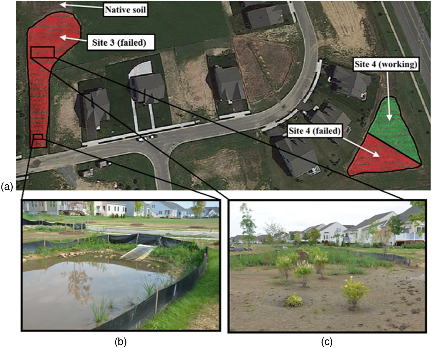
In the state of Delaware, stormwater regulations are included in Delaware’s Administrative Code under the Title 7 NREC, Section 1501 Sediment and Stormwater Regulations, and SMP guidelines are defined in the Delaware Urban Runoff Management Model (DURMM), produced by the state’s Department of Natural Resources and Environmental Control (DNREC) (Lucas 2004). The SMPs for the tract development were designed based on the DURMM guidelines for bioretention cells variant 2-B, In-Situ Bioretention (including Residential Rain Gardens), and the subcategory on infiltration. Site 3 has a drainage area of and an infiltration area of ( loading ratio). Site 4 has a drainage area of and an infiltration area of ( loading ratio) (Fig. 4).
DURMM recommends that the following soil mixture be used in rain gardens to achieve percolation within 48 h of the rain event: 50% construction sand, 20%–30% topsoil, and 20%–30% mulch. Generally consistent with this recommendation, the engineered media used to construct the bioinfiltration systems was a mix consisting of 60% concrete sand, 20% hardwood mulch, and 20% aged-certified compost per volume. According to the Natural Resources Conservation Service’s Websoil Survey tool (Soil Survey Staff, Natural Resources Conservation Service, and USDA 2016), the native soils at the site are Pinneyneck Loam and the Unicorn Loam. Both loamy soils are reported to have high hydraulic conductivities and no frequency of flooding or ponding. The bedrock underlying the sites is part of the Potomac Formation, composed of unlithified sediments, including silt, clay, and sand. Although required by the SMP specifications, the bioinfiltration systems were not constructed with capped underdrains and did not use a geotextile.
Data Collection for Sites 3 and 4
The UAF was applied to the sites, with a particular focus on potential issues associated with the media used at Sites 3 and Site 4 (Fig. 4) based on preliminary forensic field observations regarding the potential presence of clayey media. Sites 3 and 4 exhibited moderate to high ponding several days after a rain event [e.g., Fig. 4(b)], resulting in severely impaired vegetation and putrid odors being emitted from sections of the SMPs. Conversely, the native soils and surrounding areas were dry.
A double-ring infiltrometer test was performed in Site 3, the largest of the two bioinfiltration sites, and no drawdown was recorded after 60 min. In-situ infiltration tests could not be performed for Site 4 due to extreme weather conditions. No in-situ infiltration tests were performed in the native soils due to the small size of the trench where the soil samples at depth were collected. Site 3 had approximately 0.16 m (6.3 in.) of ponded water in the southern part of the rain garden even though the previous rain event had taken place two days before the infiltration tests.
Soil samples were collected from different depths at both Sites 3 and 4 for subsequent laboratory analysis. Soil media samples were collected from a depth of 0.15 m (5.9 in.) at visibly impaired locations within the bioinfiltration systems. Samples of the native soils were collected at depths of 0.7 m (27.6 in.) and 1.5 m (59.1 in.) from the ground surface directly adjacent to the SMPs (Fig. 4).
Soil samples were collected as either hand-dug grab samples or collected with the same type of soil corer described for Sites 1 and 2 previously. The grab samples were stored in sealed bags, and core samples were capped and sealed for transportation back to the laboratory.
The native soil samples collected from different depths were analyzed in the laboratory to determine if the sites were underlain by a low hydraulic conductivity layer. The samples were analyzed for gradation [ASTM D2487 (ASTM 2011)] and plasticity index [PI; ASTM D4318 (ASTM 2017c)]. The of the undisturbed soil samples was also determined in the laboratory using a falling head apparatus manufactured by Umweltanalystische Mess-Systeme (UMS) GmbH’s [DIN 19683-9 (DIN 2012); DIN 18130-1 (DIN 1998)]. Since preliminary field observations suggested potentially clayey media had been used in portions of the bioinfiltration sites (based on simple visual and manual observations of grab samples), additional soil-water-characteristic curve (SWCC) testing was also performed on undisturbed samples of the soil media. The SWCC is the constitutive relationship between matric potential and volumetric water content for the soil sample, providing important insight into the expected infiltration, storage, and drainage rates of the soil. However, SWCC measurements can be time consuming and challenging and thus are not by default typically included in the proposed UAF. If preliminary testing and/or observations specifically indicate that poor hydraulic properties of the soil media are likely contributing to infiltration underperformance, then advanced testing like SWCC measurements may be warranted. The details of the SWCC testing for these two sites are not included herein but can be found in Garza et al. (2017).
Case Study 5: SMP on University Campus in Villanova, Pennsylvania
Description of Site 5
In August 2015, a new bioinfiltration system, referred to as the Stone Hall rain garden, was built on the campus of Villanova University. This site, hereafter referred to as Site 5, was constructed simultaneously with adjacent construction occurring on campus. Shortly after construction was completed, Site 5 began to exhibit infiltration underperformance (sustained ponding). From 2016 until the present, the site has remained ponded throughout the year (Fig. 5).
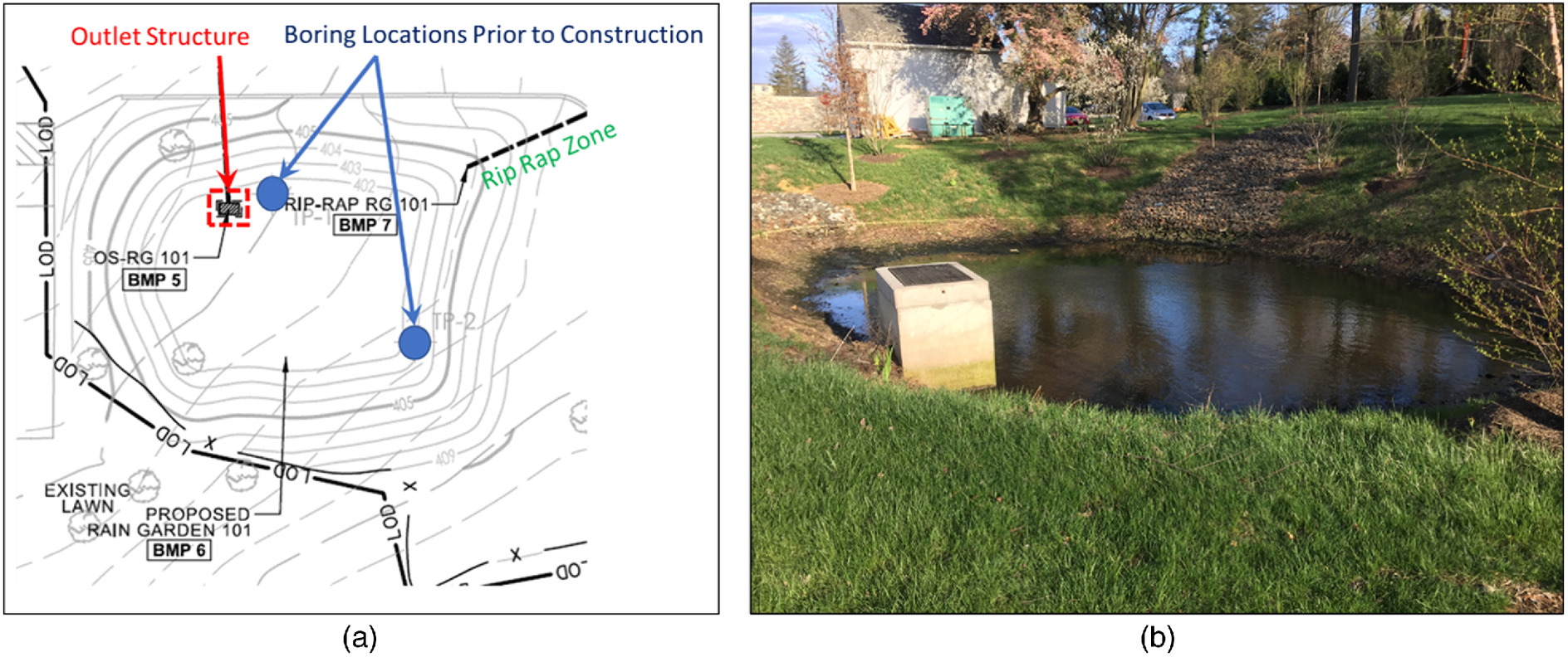
The site treats runoff from an adjacent parking lot and lawn areas on Villanova’s campus. The parking lot runoff is collected at road inlets and directed through a pipe network to the bioinfiltration system, whereas runoff from the surrounding lawns drains directly to the site. All the collected runoff enters the basin by first passing over the rip rap zone. There is no underdrain at this site. There is a concrete outlet structure (Fig. 5) that connects to the separate storm sewer system. The site was designed for a drainage area of 0.47 acres and an infiltration area of 0.04 acres, corresponding to a loading ratio.
As part of the subsurface investigation prior to construction of site 5, a geotechnical consultant performed infiltration testing and soil borings at two locations within the proposed basin. Initial borings were drilled at each infiltration test location to a depth of 2.13 m (7 ft) to determine if flow-limiting zones (e.g., rock) or shallow groundwater were present. No limiting zones or groundwater was encountered within 2.13 m (7 ft) below the ground surface. Additional geotechnical investigations performed for other construction projects in adjacent areas on campus have indicated encountering groundwater typically at a depth of 3 m (10 ft) below the ground surface. The soil encountered at both locations was identified as silty fine sand. The infiltration tests were performed by drilling secondary, 1.52 m (5 ft) deep borings next to the initial borings used to characterize the subsurface conditions and following the “Maryland Method” (Center for Water Shed Protection D.1). The measured infiltration rates for the existing underlying soil were 0.69 to (0.27 to ).
Data Collection for Site 5
From interviews with campus facilities staff, it was confirmed that nearby construction and stone cutting had been occurring adjacent to Site 5 during its construction. Due to dry, windy weather conditions at the time, potential deposition of construction dust and debris in the Site 5 basin was identified as a potential factor contributing to system underperformance and warranting further investigation. In June of 2018, the pond was pumped out to allow for site investigation including soil sample collection and spot-infiltration testing. However, complete drainage of the pond was challenging, and the basin could not be drained enough to successfully perform infiltration testing. Soil samples were collected from shallow depths (upper 0.3 m, or 12 in.), as well as some grab samples from as deep as 0.61 m (24 in.) similar to the methods described for Sites 1 and 2. Collection of deeper and/or undisturbed soil samples was not possible due to the saturated conditions. Samples were brought to the laboratory and analyzed for particle-size distribution, plasticity, organic content, and density (when possible), as described previously.
From July 2018 to October 2018, pond level data were collected using an ONSET HOBO pressure transducer. An additional HOBO was also installed to measure air pressure at the site to apply corrections to the data for relative air pressure (Onset 2018). Pond level data were used to calculate the inflow volume and estimate the recession rate. The estimated recession rate can be compared to the rain garden’s overall infiltration rate (Emerson and Traver 2008). Rainfall data were collected from a tipping bucket rain gauge located approximately 230 m from the site.
Results
Case Studies 1 and 2: Two Bioinfiltration SMPs in Philadelphia, Pennsylvania
For field infiltration rates of the media, the arithmetic and geometric means of normalized to 20°C () for each test season for each site are given in Table 1. The geometric means were consistently more conservative (lower) than the arithmetic means. All arithmetic means were above the PWD minimum infiltration requirement of () (PWD 2020) and the slightly greater PADEP infiltration rate recommendation of () (PADEP and Bureau of Watershed Management 2006). Based on the arithmetic means, there should not have been the extended periods of ponding that were observed in the field. In terms of geometric means, only two of the four geometric means for Site 1 and one of the four geometric means for Site 2 met the PWD requirement. One of the geometric means for Site 1 and none of the geometric means for Site 2 met the PADEP recommendation. These data paired with field observations suggested the geometric mean values were more representative for this study. The weighted average approach (32% arithmetic mean geometric mean; Weiss and Gulliver 2015) was also applied and resulted in values still above the PWD requirements.
| Site | Mean type | Fall 2017 | Spring 2018 | Summer 2018 | Fall 2018 |
|---|---|---|---|---|---|
| Site 1 | Arithmetic mean () | 9.4 | 2.1 | 5.8 | 4.2 |
| Geometric mean () | 1.1 | 0.50 | 1.8 | 0.42 | |
| Site 2 | Arithmetic mean () | 7.3 | 2.6 | 5.1 | 1.5 |
| Geometric mean () | 0.41 | 0.31 | 1.2 | 0.36 |
It is important to note that methods such as a synthetic drawdown test, simulated runoff test, or recession rate monitoring may provide a more representative estimate of the infiltration rate for the site as a whole, compared to calculating a representative value from multiple infiltration tests. However, such larger-scale measurements would not allow for identifying specific problematic areas that may be contributing to underperformance. Thus, spot-infiltration tests are still an important assessment method within the UAF to provide more targeted rehabilitation recommendations (e.g., only a portion of the basin may require rehabilitation). As with all field testing, the UAF user should apply site-specific engineering judgment as to which infiltration test techniques and analysis methods are most appropriate for the number of tests, size of the site, overall range of values across the site, and constraints of the project. Since both single-ring and double-ring infiltration tests methods have been shown to be accurate predictors of SCM performance (Zukowski et al. 2016), and the results of infiltration testing can be highly spatially variable, it is recommended that the UAF user choose the test method that would allow them to perform the most tests within the budget and time constraints. Even though in this study the results obtained from using the geometric mean were determined to be the most representative based on corresponding field observations, the UAF user is encouraged to confirm how the analysis method impacts the conclusions from the infiltration testing before making rehabilitation recommendations based on the results. Calculations to determine the arithmetic mean, geometric mean, and weighted average (Weiss and Gulliver 2015) are simple to perform and should always be compared with field ponding observations and engineering judgment. The bioinfiltration media was classified based on the USDA and USCS classification schemes. Based on USDA classification, all the collected media samples from Sites 1 and 2 were categorized either as sand, loamy sand, or sandy loam. Texture results (percent sand, silt, and clay) were within recommended guidelines by the PADEP and Bureau of Watershed Management (2006) and the PWD (2020). Based on the USCS classification, which also considers soil plasticity, the Site 1 media samples classified as either well-graded sand with gravel (SW), poorly graded sand with gravel (SP), well-graded sand with silt and gravel (SW-SM), or silty sand (SM). For Site 2 media, soil samples classified according to USCS were either silty sand with gravel (SM), well-graded sand with silt and gravel (SW-SM), poorly graded sand with silt and gravel (SP-SM), or silty sand (SM). Thus, based on the results of texture and particle-size distribution, the media at both bioinfiltration sites should have exhibited acceptable infiltration rates if constructed properly.
Samples collected from the underlying subgrade at Site 1 were all classified as loamy sand and sandy loam per USDA. For Site 2, samples from the underlying subgrade were classified as sand or loamy sand. The USCS soil classification results showed most (16 of 17) native soil samples from Site 1 classified as silty SW (SM), and one was classified as silty sand (SM). For Site 2, USCS soil classification results showed three subgrade soil samples classified as silty sand (SM) and one as silty clayey sand (SC-SM). Literature and municipal guideline recommendations suggest rain gardens will operate well with sandy and silty subgrade soils (e.g., PADEP and Bureau of Watershed Management 2006; PWD 2020). The subgrade soil type at site 1 is likely not causing infiltration performance issues.
The PWD (2020) Manual recommends using uncompacted sand, loamy sand, or sandy loam soil for use in rain gardens and SMPs. The density for typical uncompacted loamy sand soil may range from 1.0 to , while the density for compacted loamy sand soil may exceed (PADEP and Bureau of Watershed Management 2006). For both Sites 1 and 2, the dry density of the soil media was determined from undisturbed soil core samples taken from the surface to a depth of 45.7 cm (18 in.). The dry density of the media varied from 1.0 to for Site 1 and from 1.10 to for Site 2, falling within recommended ranges from PADEP and Bureau of Watershed Management (2006). The density of the underlying subgrade soils at both sites ranged from 1.37 to , although quality undisturbed cores were difficult to obtain. Therefore, compaction of rain garden media soil is likely not impacting the performance at Sites 1 and 2. Compaction of subgrade soil may impact performance at Sites 1 and 2.
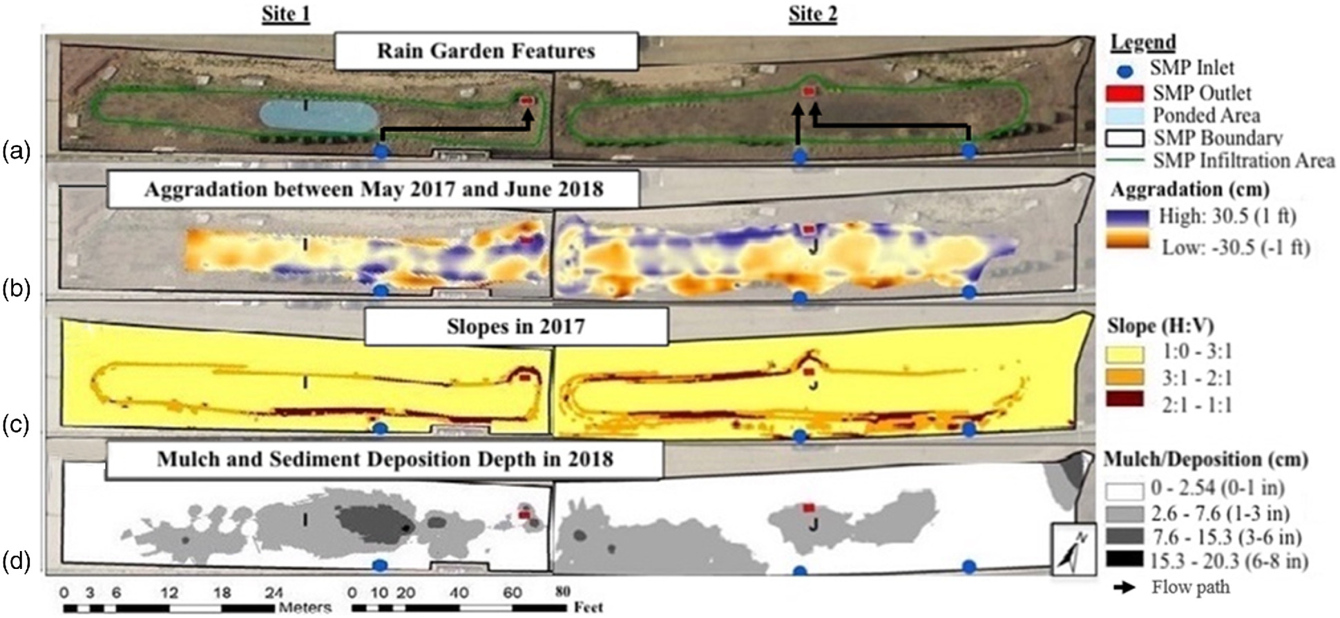
Spatial correlations were observed between mulch and sediment deposition depth, slopes, aggradation, low infiltration, and ponded areas for Sites 1 and 2, as shown in Fig. 6. In panel D of Fig. 6, the upstream areas of Site 1 to the left of the figure have mulch thicknesses below the recommended depths of 2.6 to 7.6 cm (1–3 in.); this trend reverses downstream toward the outlet structure, seeing as the deepest mulch and sediment deposition is near the inlet. In Fig. 6 panel D for Site 2, generally, the mulch is moving downstream within the system, similarly to Site 1. Areas upstream, especially upstream of both inlets, show mulch depths less than the recommended mulch thickness of 2.6 to 7.6 cm (1 to 3 in.) (PADEP and Bureau of Watershed Management 2006; PWD 2020).
Other possible causes of underperformance include inflow or underdrain failure. At Site 1, the contributing drainage area had changed, leading up to underperformance due to alterations on the highway deck, especially through the movement of jersey barriers. It was considered that this could be routing additional flow to the site. Inflow was analyzed by comparing inflow values calculated using the rational method to observe inflow measurements. The observed flow was well below the estimated flow. The difference suggests that the site was not receiving inflow beyond its design, but may be receiving less flow than designed.
After sustained ponding was observed at the sites and they were identified as underperforming, the underdrains were opened in an attempt to reduce drain-down times. However, sustained ponding continued to occur even after opening the underdrains. Visual inspections from opening the end caps of the underdrain in Site 1 showed no obvious soil at the end of the underdrain. Further inspection with a drain scope camera revealed deposits of sediment throughout the length of the underdrain, but not to an extent that would suggest clogging. It is possible that soil accumulation in the underdrain was affecting performance. Further work is required to estimate the impact of the soil deposits. Assessment of the SMP will be completed following rehabilitation to resolve the UAF analysis.
Case Studies 3 and 4: Two Bioinfiltration SMPs in a Tract Development in Glasglow, Delaware
Soil samples collected from case study Sites 3 and 4 from the SMPs in Delaware were analyzed in the laboratory at Villanova University. The Site 3 media had a lower percentage of fines compared to the native soils collected at 0.7 m below the basin surface. The Atterberg limits provided insight on the type of fines that each soil contained. The media used at both sites contained a significant clay fraction based on the measure PI of 16 for Site 3 and 13 for Site 4. (Table 2). The grain-size distribution and the Atterberg limits were used to classify the soils according to USCS and USDA. Based on the USDA classification alone, which indicated the media was sandy loam, the media would have been considered appropriate for use in a bioinfiltration system. However, additional consideration of soil plasticity (i.e., using USCS classification) clearly reveals the correlation between the failed sections of the SMPs and the presence of clayey media, as shown in Table 2.
| Location | Classification | Plasticity index (PI) | () | |
|---|---|---|---|---|
| USCS | USDA | |||
| Site 3- failed | Clayey sand (SC) | Sandy loam | 13 | 0.007 |
| Site 4- failed | Clayey sand (SC) | Sandy loam | 16 | 0.003 |
| Site 4- working | Silty sand with gravel (SM) | Gravelly sandy loam | Nonplastic | 0.013 |
| Native soil - 0.7 m | Silty sand (SC) | Sandy loam | Nonplastic | — |
| Native soil - 1.5 m | Silty sand (SC) | Sandy loam | Nonplastic | 0.14 |
From field observations, the of the native soils was noticeably greater than that of the engineered soils, such that the use of the already in-situ soils may have been preferable to importing and placing engineered media. The sites were not built with underdrains, and shallow groundwater levels were not observed in the area. Additional investigation of the sites was not performed after the use of inappropriate media was identified as a root cause of underperformance.
Case Study 5: SMP on University Campus in Villanova, Pennsylvania
Although spot-infiltration tests could not be performed at Site 5, the recession rate could still be determined from the pressure transducer measurements. The recession rate yields the drain time after a rain event and can be considered representative of the entire system, mitigating measurement variability due to small-scale heterogeneities often observed for spot-infiltration tests (Ebrahimian et al. 2020). Collected data for rainfall data, pond level data, and the outlet height are compared in Fig. 7.
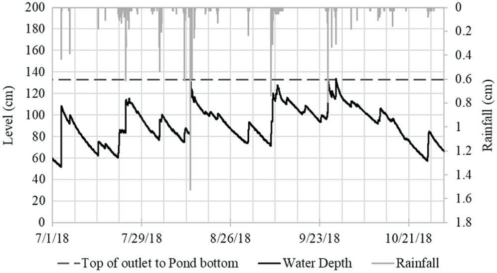
From the data in Fig. 7, the average water level recession rate over the period from July 2018 to October 2018 was only (), This low rate is consistent with the observed sustained ponding and falls well below recommended infiltration rates for a bioinfiltration system [ for the amended media, per PADEP and Bureau of Watershed Management (2006) and PWD (2020)].
Laboratory analysis of the soil samples collected from the upper 50.8 cm (20 in.) of the basin indicated that the soil was generally classified as sand or loamy sand per USDA soil classification. The USCS soils classification results indicated the soil was silty sand (SM) or silty SW (SP-SM). Thus, based on measurement of both the full particle-size distribution and the soil plasticity, the media retrieved from the upper 50.8 cm (20 in.) at multiple locations within the site was appropriate for use in a bioinfiltration system.
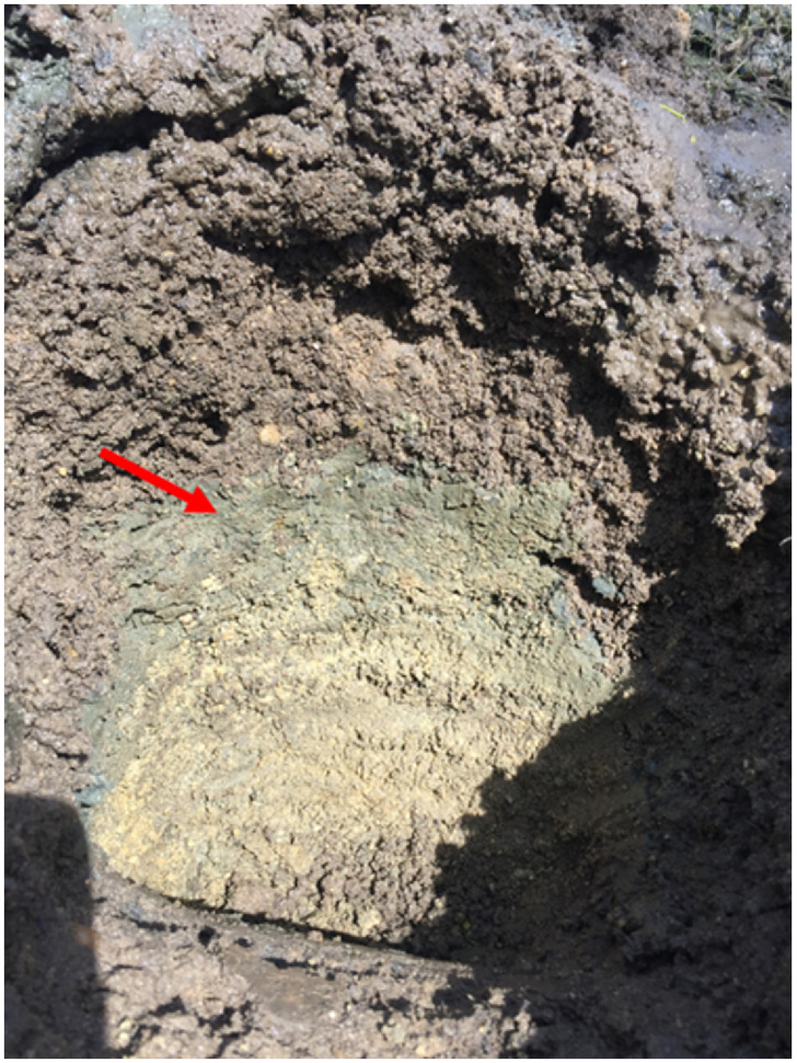
However, attempts to collect samples from deeper than 50.8 cm (20 in.) using the hand auger were unsuccessful due to encountering a very stiff layer. A small test hole was dug as documented by Fig. 8, indicating the potential presence of a thin, fine-grained restrictive layer below a portion of the infiltration media. However, further exploration and sampling could not be performed due to difficulty in fully pumping out the basin. A final assessment of the SMP will be completed following rehabilitation to complete the loop for the UAF analysis.
Discussion
Through a holistic systematic analysis, potential culprits driving the underperformance of five SMPs across three project locations were identified. Perhaps of equal importance, several parameters were found innocent of impeding infiltration. The causes of underperformance identified for each of the three project locations were different, emphasizing the limitations of a “one-size-fits-all” approach to forensic investigation and rehabilitation of bioinfiltration systems. Causes of underperformance ranged widely, including steep slopes leading to accumulation on the basin surface (Sites 1 and 2), use of compost that degraded into a high plasticity layer in some portions of the bioinfiltration systems (Sites 3 and 4), and the presence of a restrictive layer below the media (Site 5). By breaking down the function of each parameter of the SMP, specific recommendations for rehabilitation and remediation can be identified targeting only the underperforming components (Table 3).
| Component | Potential cause of underperformance | Rehabilitation recommendation | Case study site # | ||||
|---|---|---|---|---|---|---|---|
| 1 | 2 | 3 | 4 | 5 | |||
| Amended media | Poor media | Remove/replace or further amend the soil in identified locations | — | — | — | ||
| — | — | — | — | — | |||
| Compaction | Decompact (e.g., tilling) | — | — | — | — | — | |
| Underlying soil | Poorly infiltrating soil | Consider conversion to bioretention | — | — | — | — | — |
| Dense/compacted | — | — | — | — | — | ||
| Unknown subsurface materials | Unknown restrictive layer or factors | Remove, punch through, or convert to bioretention | — | — | — | — | |
| Basin surface | Steep slopes | Regrade slopes | — | — | — | ||
| Aggradation or deposition | Remove surficial layer specified depth /locations | — | — | — | |||
| Mulch accumulation | Remove mulch layer in identified areas | — | — | — | — | ||
| Inflows and inlet design | High inflow | Modify basin or drainage area size, or re-route/divert flows | — | — | — | — | — |
| High sediment contribution | Install inlet forebays or modify flow path to collect sediment | — | — | — | |||
| Groundwater | High groundwater | Dependent on depth to groundwater | — | — | — | — | |
| Underdrain (if present) | Clogged underdrain | Clean underdrain | — | — | — | ||
| Crushed underdrain | Remove/replace underdrain | — | — | — | — | — | |
Note: C = likely cause contributing to underperformance; and P = possible problem warranting additional assessment.
Site 1
SMP media and subgrade soils beneath Site 1 are within USDA soil classification recommendations provided by the PADEP and Bureau of Watershed Management (2006) and PWD (2020) Stormwater BMP manuals, as well as USCS soil classification recommendations from literature, are likely not contributing to the infiltration performance issues present at either site. The density of the rain garden media in Site 1 is well below the upper limit for the dry density of uncompacted loamy sand of and is therefore unlikely compacted and a cause of system underperformance. Compaction of native soils beneath Site 1 could not be ruled out as a possible contributor to the infiltration underperformance.
Spatial analysis showed areas draining steep side slopes were found to correlate with areas of aggradation of soil and areas with a thick mulch layer, suggesting that over time mulch and soil had migrated down the steep side slopes and accumulated up to depths of 21 cm (8 in.), as corroborated by field observations. Mulch had also migrated downslope within the basin. Visual observations of the splash aggregate pad in Site 1 included large aggregate displacement, suggesting that design flows for the system had been exceeded. The sediment deposition near the inlet was the result of high energy flow entering through the inlet perpendicularly to the main flow path. This had forced a geomorphic change within the SMP, resulting in the creation of a cutoff point by shifting the deposition culmination from the steep slopes, ultimately altering the rain garden configuration. The cutoff forces isolation of the upstream ponded area from the downstream draining area. While downstream may have good infiltration potential, water is retained upstream, causing persistent ponding in the SMP. To address this, rehabilitation recommendations include regrading the slopes to correct the steep slopes and to remove, and replace, as needed, media and mulch to correct for media and mulch accumulation within the system. Substituting domed risers for underdrain cleanout caps is also recommended to improve drainage in areas where ponding occurs.
Site 2
Although there was not as clear of a consistently ponded area in Site 2 as there was in Site 1, ponding times exceeding design ponding times were observed at the site. Similar to Site 1, rain garden media and subgrade soil types of Site 2 are likely not contributing to the infiltration performance issues, seeing as they are within USDA and USCS soil classification recommendations. The majority of the media samples for Site 2 were also below the upper limit for the recommended dry density of uncompacted loamy sand (with the exception of one sample which slightly exceeded this range, but is still not considered compacted); therefore, compaction of the Site 2 media is likely not a problem in this system. Similar to Site 1, compaction of underlying soils beneath Site 2 could not be ruled out as a possible contributor to the underperformance.
Spatial trends suggest depositional areas occur near steep side slopes, although to a lesser extent than Site 1 that exhibits more deposition than in Site 2. Although it is apparent that mulch is moving downstream within the system, mulch depths do not exceed the recommended depth range and are unlikely an issue in this system. Unlike Site 1, there is no restriction in the flow path. The use and configuration of double inlets in Site 2 seem to improve the flow path, contrasting the use and configuration of a single inlet in Site 1. It is likely that each of these factors individually is not the cause of infiltration underperformance, but the combination of them. Recommendations include regrading the slopes in this system, as well as removing rain garden media in areas of media accumulation, summarized in Table 3.
Sites 3 and 4
Lab characterization of samples from these sites suggests that the overuse of compost that degraded to high plasticity materials is the likely culprit for the underperformance of these systems (Table 3). The rehabilitation recommendation for Sites 3 and 4 was to replace or amend the soil media to media that better facilitates infiltration of water or to introduce an underdrain to the system. Notably, the soil mixture composition was technically compliant to local regulations for bioinfiltration media, further supporting the need for more robust soil specification approaches that also consider soil plasticity. Through systematic analysis of the basin slopes, sediment and mulch accumulation, and inflow designs, these items were determined to not be negatively impacting the infiltration in these two systems. To remediate the underperformance, the developers of Sites 3 and 4 introduced trench drains for rehabilitation. Since implementation, infiltration and function of these sites have increased. Further study is needed on the impact of incorporating trench drains into a system as a form of remediation and whether it should be adopted into design standards and construction techniques.
Site 5
For Site 5, infiltration testing and deeper undisturbed core sampling could not be performed adequately due to the persistent ponding at the site. However, the collection of soil cores in the upper 50.8 cm (20 in.) indicated that the media generally classified as sandy loam. Thus, the use of inappropriate soil media was ruled out as the cause of underperformance. Difficulty advancing the hand auger beyond the 50.8 cm (20 in.) depth, combined with observations from staff present during the initial construction, supports the potential for an unexpected restrictive layer (e.g., due to construction dust/debris accumulation, or a dense clayey layer not discovered during the initial investigation) existing at 50.8 cm (20 in.) depth or deeper that has been inhibiting infiltration. Rehabilitation options for the presence of a subsurface restrictive layer are more challenging than the previously described case studies. At the time of writing, infiltration at the site had not yet been restored and restoration actions were still being explored. In addition, a high or fluctuating groundwater table could not be ruled out as a potential contributor to the underperformance. Notably, there are limited possible remedies for groundwater intrusion into bioinfiltration sites that have already been constructed. Issues associated with high groundwater are best managed if prevented altogether through a thorough site investigation and proper site selection. If groundwater intrusion is observed during construction, swift corrective actions (e.g., postbid construction revisions) can sometimes be made before construction is completed.
Conclusions
Through a holistic systematic investigation of these five bioinfiltration systems using the UAF, researchers were able to decipher probable drivers of inadequate infiltration in these case studies. Comprehensive and systematic investigations of different rain garden components allowed for a holistic understanding of which components were performing as intended and which were failing to meet the design objective. Underperforming components were isolated as potential culprits of system infiltration. By linking likely causes of underperformance with targeted rehabilitation techniques, an entire system overhaul may be avoidable. In lieu of system re-build, the identified underperforming components can be altered to restore performance. This will ultimately assuage the financial and temporal cost of SMP ownership.
Implementation of SMPs in the urban environment is rapidly expanding in efforts to mitigate negative impacts on water quality and quantity. As these systems become increasingly prevalent a fundamental understanding regarding the minutiae of these systems is imperative to make them cost and management effective. The use of systematic tools such as the UAF presented herein facilitates this understanding and opens the door to more effective and efficient management of SMPs. A better grasp on the causes of SMP underperformance will inform optimal design and maintenance of these systems, ensuring their future longevity and resiliency.
Data Availability Statement
All soil and infiltration data generated in the study are available from the corresponding author by request.
Acknowledgments
The authors would like to thank the PennDOT and the William Penn Foundation for their support and funding. The opinions presented in this article/publication are those of the authors and do not necessarily express the opinions of the PennDOT or the William Penn Foundation. References in this report to any commercial product, process, or service, or the use of any trade, firm, or corporation name is for general informational purposes only and do not constitute an endorsement or certification of any kind by the authors. The authors are gracious for past graduate students who have informed this work and have aided in the collection of soil samples, as well as for undergraduates who performed laboratory soil analyses resulting in the numerical data present in this work.
Disclaimer
The opinions presented in this publication are those of the authors and do not necessarily express the opinions of the PennDOT. References in this report to any commercial product, process, or service, or the use of any trade, firm, or corporation name are for general informational purposes only and do not constitute an endorsement or certification of any kind by the authors. This project is a research initiative of the Villanova Center for Resilient Water Systems.
References
Ahiablame, L. M., B. A. Engel, and I. Chaubey. 2012. “Effectiveness of low impact development practices: Literature review and suggestions for future research.” Water Air Soil Pollut. 223 (7): 4253–4273. https://doi.org/10.1007/s11270-012-1189-2.
Asleson, B. C., R. S. Nestingen, J. S. Gulliver, R. M. Hozalski, and J. L. Nieber. 2009. “Performance assessment of rain gardens.” JAWRA J. Am. Water Resour. Assoc. 45 (4): 1019–1031. https://doi.org/10.1111/j.1752-1688.2009.00344.x.
ASTM. 2011. Standard practice for classification of soils for engineering purposes (unified soil classification system). ASTM D2487-11. West Conshohocken, PA: ASTM.
ASTM. 2017a. Standard test method for density of soil in place by the drive-cylinder method. ASTM D2937-17e2. West Conshohocken, PA: ASTM.
ASTM. 2017b. Standard test method for particle-size distribution (gradation) of fine-grained soils using the sedimentation analysis. ASTM D7928-17. West Conshohocken, PA: ASTM.
ASTM. 2017c. Standard test methods for liquid limit, plastic limit, and plasticity index of soils. ASTM D4318-17e1. West Conshohocken, PA: ASTM.
ASTM. 2017d. Standard test methods for particle-size distribution (gradation) of soils using sieve analysis. D6913/D6913M-17. West Conshohocken, PA: ASTM.
ASTM. 2019. Standard test methods for laboratory determination of water (moisture) content of soil and rock by mass. ASTM D2216-19. West Conshohocken, PA: ASTM.
ASTM. 2020. Standard test methods for determining the water (moisture) content, ash content, and organic material of peat and other organic soils. ASTM D2974-20e1. West Conshohocken, PA: ASTM.
Bell, C. D., S. K. McMillan, S. M. Clinton, and A. J. Jefferson. 2016. “Hydrologic response to stormwater control measures in urban watersheds.” J. Hydrol. 541 (Oct): 1488–1500. https://doi.org/10.1016/j.jhydrol.2016.08.049.
Blecken, G. T., W. F. Hunt III, A. M. Al-Rubaei, M. Viklander, and W. G. Lord. 2017. “Stormwater control measure (SCM) maintenance considerations to ensure designed functionality.” Urban Water J. 14 (3): 278–290. https://doi.org/10.1080/1573062X.2015.1111913.
Bouwer, H. 2002. “Artificial recharge of groundwater: Hydrogeology and engineering.” Hydrogeol. J. 10 (1): 121–142. https://doi.org/10.1007/s10040-001-0182-4.
Braga, A., M. Horst, and R. G. Traver. 2007. “Temperature effects on the infiltration rate through an infiltration basin BMP.” J. Irrig. Drain. Eng. 133 (6): 593–601. https://doi.org/10.1061/(ASCE)0733-9437(2007)133:6(593).
Brown, R. A., and W. F. Hunt III. 2010. “Impacts of construction activity on bioretention performance.” J. Hydrol. Eng. 15 (6): 386–394. https://doi.org/10.1061/(ASCE)HE.1943-5584.0000165.
Catalano de Sousa, M. R., F. A. Montalto, and P. Gurian. 2016. “Evaluating green infrastructure stormwater capture performance under extreme precipitation.” J. Extreme Events 3 (2): 1650006. https://doi.org/10.1142/S2345737616500068.
Davis, A. P. 2008. “Field performance of bioretention: Hydrology impacts.” J. Hydrol. Eng. 13 (2): 90–95. https://doi.org/10.1061/(ASCE)1084-0699(2008)13:2(90).
Debbage, N., B. Bereitschaft, and J. M. Shepherd. 2017. “Quantifying the spatiotemporal trends of urban sprawl among large US metropolitan areas via spatial metrics.” Appl. Spatial Anal. Policy 10 (3): 317–345. https://doi.org/10.1007/s12061-016-9190-6.
DelGrosso, Z. L., C. C. Hodges, and R. L. Dymond. 2019. “Identifying key factors for implementation and maintenance of green stormwater infrastructure.” J. Sustainable Water Built Environ. 5 (3): 05019002. https://doi.org/10.1061/JSWBAY.0000878.
Dietz, M. E. 2007. “Low impact development practices: A review of current research and recommendations for future directions.” Water Air Soil Pollut. 186 (1–4): 351–363. https://doi.org/10.1007/s11270-007-9484-z.
DIN (German Institute for Standardization). 1998. Geotechnical investigation and testing—Determination of permeability by constant and falling head. DIN 18130-1. Berlin: DIN.
DIN (German Institute for Standardization). 2012. Soil quality—Physical laboratory tests. DIN 19683-9. Berlin: DIN.
DPWES and MSMD (Fairfax County Dept. of Public Works and Environmental Services and Maintenance and Stormwater Management Division). 2017. Fairfax County 2019 MS4 program plan and annual report, appendix P10: Post-construction stormwater inspection and maintenance policies and procedures. Woodbridge, VA: County of Fairfax, Virginia.
Ebrahimian, A., K. Sample-Lord, B. Wadzuk, and R. Traver. 2020. “Temporal and spatial variation of infiltration in urban green infrastructure.” Hydrol. Processes 34 (4): 1016–1034. https://doi.org/10.1002/hyp.13641.
Emerson, C. H., and R. G. Traver. 2008. “Multiyear and seasonal variation of infiltration from storm-water best management practices.” J. Irrig. Drain. Eng. 134 (5): 598–605. https://doi.org/10.1061/(ASCE)0733-9437(2008)134:5(598).
Emerson, C. H., B. M. Wadzuk, and R. G. Traver. 2010. “Hydraulic evolution and total suspended solids capture of an infiltration trench.” Hydrol. Processes 24 (8): 1008–1014. https://doi.org/10.1002/hyp.7539.
Environmental Services Division, Dept. of Environmental Resources, and The Prince George’s County, Maryland. 2007. Bioretention manual. Upper Marlboro, MD: Prince George’s County of Maryland.
Erickson, A. J., V. J. Taguchi, and J. S. Gulliver. 2018. “The challenge of maintaining stormwater control measures: A synthesis of recent research and practitioner experience.” Sustainability 10 (10): 3666. https://doi.org/10.3390/su10103666.
Fassman-Beck, E., S. Wang, R. Simcock, and R. Liu. 2015. “Assessing the effects of bioretention’s engineered media composition and compaction on hydraulic conductivity and water holding capacity.” J. Sustainable Water Built Environ. 1 (4): 04015003. https://doi.org/10.1061/JSWBAY.0000799.
Flynn, K. M., B. W. Linkous, and M. T. Buechter. 2012. “Operation and maintenance assessment for structural stormwater BMPs.” In Proc., World Environmental and Water Resources Congress 2012, 3662–3673. Reston, VA: ASCE.
Garza, P., Z. Zukowski, A. Welker, and D. LaBrake. 2017. “Comparison of field and laboratory methods for measuring hydraulic conductivity in the unsaturated zone in engineered and native soils.” In Geotechnical Frontiers 2017: Geotechnical Materials, Modeling, and Testing, Geotechnical Special Publication 280, edited by T. L. Brandon and R. J. Valentine, 709–718. Reston, VA: ASCE.
Guo, J. C. Y. 2012. “Cap-orifice as a flow regulator for rain garden design.” J. Irrig. Drain. Eng. 138 (2): 198–202. https://doi.org/10.1061/(ASCE)IR.1943-4774.0000399.
Hatt, B. E., T. D. Fletcher, and A. Deletic. 2007. “Treatment performance of gravel filter media: Implications for design and application of stormwater infiltration systems.” Water Res. 41 (12): 2513–2524. https://doi.org/10.1016/j.watres.2007.03.014.
Houle, J. J., R. M. Roseen, T. P. Ballestero, T. Puls, and J. Sherrard Jr. 2013. “Comparison of maintenance cost, labor demands, and system performance for LID and conventional stormwater management.” J. Environ. Eng. 139 (7): 932–938. https://doi.org/10.1061/(ASCE)EE.1943-7870.0000698.
Hunt, W., and B. Lord. 2006. “Wetland-and-pond-maintenance-2006.pdf.” Accessed August 12, 2020. https://brunswick.ces.ncsu.edu/wp-content/uploads/2013/04/Wetland-and-Pond-Maintenance-2006.pdf?fwd=no.
Hunt, W. F., A. P. Davis, and R. G. Traver. 2012. “Meeting hydrologic and water quality goals through targeted bioretention design.” J. Environ. Eng. 138 (6): 698–707. https://doi.org/10.1061/(ASCE)EE.1943-7870.0000504.
Jarden, K. M., A. J. Jefferson, and J. M. Grieser. 2016. “Assessing the effects of catchment-scale urban green infrastructure retrofits on hydrograph characteristics.” Hydrol. Processes 30 (10): 1536–1550. https://doi.org/10.1002/hyp.10736.
Jayasooriya, V. M., and A. W. M. Ng. 2014. “Tools for modeling of stormwater management and economics of green infrastructure practices: A review.” Water Air Soil Pollut. 225 (8): 1–20. https://doi.org/10.1007/s11270-014-2055-1.
Jaynes, D. B. 1990. “Temperature variations effect on field-measured infiltration.” Soil Sci. Soc. Am. J. 54 (2): 305–312. https://doi.org/10.2136/sssaj1990.03615995005400020002x.
Jefferson, A. J., A. S. Bhaskar, K. G. Hopkins, R. Fanelli, P. M. Avellaneda, and S. K. McMillan. 2017. “Stormwater management network effectiveness and implications for urban watershed function: A critical review.” Hydrol. Processes 31 (23): 4056–4080. https://doi.org/10.1002/hyp.11347.
Jenkins, J. K. G., B. M. Wadzuk, and A. L. Welker. 2010. “Fines Accumulation and distribution in a storm-water rain garden nine years postconstruction.” J. Irrig. Drain. Eng. 136 (12): 862–869. https://doi.org/10.1061/(ASCE)IR.1943-4774.0000264.
Lai, F., J. Zhen, J. Riverson, and L. Shoemaker. 2006. “SUSTAIN—An evaluation and cost-optimization tool for placement of BMPs.” In Proc., World Environmental and Water Resource Congress 2006, 1–13. Reston, VA: ASCE.
Langergraber, G., R. Haberl, J. Laber, and A. Pressl. 2003. “Evaluation of substrate clogging processes in vertical flow constructed wetlands.” Water Sci. Technol. 48 (5): 25–34. https://doi.org/10.2166/wst.2003.0272.
Le Coustumer, S., T. D. Fletcher, A. Deletic, S. Barraud, and J. F. Lewis. 2009. “Hydraulic performance of biofilter systems for stormwater management: Influences of design and operation.” J. Hydrol. 376 (1–2): 16–23. https://doi.org/10.1016/j.jhydrol.2009.07.012.
Le Coustumer, S., T. D. Fletcher, A. Deletic, S. Barraud, and P. Poelsma. 2012. “The influence of design parameters on clogging of stormwater biofilters: A large-scale column study.” Water Res. 46 (20): 6743–6752. https://doi.org/10.1016/j.watres.2012.01.026.
LeFevre, G. H., K. H. Paus, P. Natarajan, J. S. Gulliver, P. J. Novak, and R. M. Hozalski. 2015. “Review of dissolved pollutants in urban storm water and their removal and fate in bioretention cells.” J. Environ. Eng. 141 (1): 04014050. https://doi.org/10.1061/(ASCE)EE.1943-7870.0000876.
Lindsey, G., L. Roberts, and W. Page. 1992. “Inspection and maintenance of infiltration facilities.” J. Soil Water Conserv. 47 (6): 481–486.
Lucas, W. 2004. Green technology: The Delaware urban runoff management approach. London: Division of Soil and Water Conservation.
METER Group. 2017. “SATURO infiltrometer manual.” Accessed November 20, 2018. http://library.metergroup.com/Manuals/20496_SATURO_Manual.pdf.
Minnesota Pollution Control Agency and Minnesota Stormwater Steering Committee. 2008. Minnesota stormwater manual, 885. St. Paul, MN: Minnesota Pollution Control Agency.
Olson, N. C., J. S. Gulliver, J. L. Nieber, and M. Kayhanian. 2013. “Remediation to improve infiltration into compact soils.” J. Environ. Manage. 117 (Mar): 85–95. https://doi.org/10.1016/j.jenvman.2012.10.057.
Onset. 2018. “HOBO water level data logger.” Accessed March 20, 2019. https://www.onsetcomp.com/products/data-loggers/u20l-01.
PADEP (Pennsylvania Dept. of Environmental Protection) and Bureau of Watershed Management. 2006. Pennsylvania stormwater best management practices manual. Harrisburg, PA: PADEP and Bureau of Watershed Management.
Pitt, R., S.-E. Chen, S. E. Clark, J. Swenson, and C. K. Ong. 2008. “Compaction’s impacts on urban storm-water infiltration.” J. Irrig. Drain. Eng. 134 (5): 652–658. https://doi.org/10.1061/(ASCE)0733-9437(2008)134:5(652).
Portland Bureau of Environmental Services. 2016. City of Portland stormwater management manual, 502. Portland, OR: Portland Bureau of Environmental Services.
Press, J. 2019. “Determining the minimum number of single ring infiltration tests required to reliably predict performance of a rain garden.” Master’s thesis, Dept. of Civil and Environmental Engineering, Villanova Univ.
PWD (Philadelphia Water Dept.). 2020. Stormwater management guidance manual. Version 3.2. Philadelphia: PWD.
Reddi, L. N., X. Ming, M. G. Hajra, and I. M. Lee. 2000. “Permeability reduction of soil filters due to physical clogging.” J. Geotech. Geoenviron. Eng. 126 (3): 236–246. https://doi.org/10.1061/(ASCE)1090-0241(2000)126:3(236).
Roy-Poirier, A., P. Champagne, and Y. Filion. 2010. “Review of bioretention system research and design: Past, present, and future.” J. Environ. Eng. 136 (9): 878–889. https://doi.org/10.1061/(ASCE)EE.1943-7870.0000227.
Scholes, L., D. M. Revitt, and J. B. Ellis. 2008. “A systematic approach for the comparative assessment of stormwater pollutant removal potentials.” J. Environ. Manage. 88 (3): 467–478. https://doi.org/10.1016/j.jenvman.2007.03.003.
Shafique, M., and R. Kim. 2017. “Green stormwater infrastructure with low impact development concept: A review of current research.” Desalin. Water Treat. 83 (7): 16–29. https://doi.org/10.5004/dwt.2017.20981.
Sileshi, R., R. Pitt, and S. Clark. 2018. “Performance evaluation of an alternative underdrain material for stormwater biofiltration systems.” J. Sustainable Water Built Environ. 4 (2): 04018002. https://doi.org/10.1061/JSWBAY.0000845.
Siriwardene, N., A. Deletic, and T. Fletcher. 2007. “Clogging of stormwater gravel infiltration systems and filters: Insights from a laboratory study.” Water Res. 41 (7): 1433–1440. https://doi.org/10.1016/j.watres.2006.12.040.
Smith, C., R. Connolly, R. Ampomah, A. Hess, K. Sample-Lord, and V. Smith. 2021. “Temporal soil dynamics in bioinfiltration systems.” J. Irrig. Drain. Eng. 147 (11): 04021053.
Soil Survey Staff, Natural Resources Conservation Service, and United States Dept. of Agriculture. 2016. “Web soil survey.” Accessed March 20, 2019. http://websoilsurvey.sc.egov.usda.gov/.
Tu, M.-C., and R. G. Traver. 2019. “Optimal configuration of an underdrain delivery system for a stormwater infiltration trench.” J. Irrig. Drain. Eng. 145 (8): 05019007. https://doi.org/10.1061/(ASCE)IR.1943-4774.0001408.
USEPA. 1999. “Storm water technology fact sheet-bioretention.” Accessed August 12, 2020. https://nepis.epa.gov/Exe/ZyPDF.cgi/200044BE.PDF?Dockey=200044BE.PDF.
USEPA. 2000. “Stormwater phase II final rule post-construction runoff control minimum control measure.” Accessed August 12, 2020. https://www3.epa.gov/npdes/pubs/fact2-7.pdf.
Virahsawmy, H. K., M. J. Stewardson, G. Vietz, and T. D. Fletcher. 2014. “Factors that affect the hydraulic performance of raingardens: Implications for design and maintenance.” Water Sci. Technol. 69 (5): 982–988. https://doi.org/10.2166/wst.2013.809.
Wadzuk, B., B. Gile, V. Smith, A. Ebrahimian, and R. Traver. 2021. “Call for a dynamic approach to GSI maintenance.” J. Sustainable Water Built Environ. 7 (2): 02521001. https://doi.org/10.1061/JSWBAY.0000945.
Weiss, P. T., and J. S. Gulliver. 2015. “Effective saturated hydraulic conductivity of an infiltration-based stormwater control measure.” J. Sustainable Water Built Environ. 1 (4): 04015005. https://doi.org/10.1061/JSWBAY.0000801.
William, R., P. Gardoni, and A. S. Stillwell. 2019. “Reliability-based approach to investigating long-term clogging in green stormwater infrastructure.” J. Sustainable Water Built Environ. 5 (1): 04018015. https://doi.org/10.1061/JSWBAY.0000875.
WSU and PSP (Washington State University Extension and Puget Sound Partnership). 2012. Low impact development technical guidance manual for Puget Sound. Tacoma, WA: WSU and PSP.
Zhang, K., and T. F. M. Chui. 2019. “A review on implementing infiltration-based green infrastructure in shallow groundwater environments: Challenges, approaches, and progress.” J. Hydrol. 579 (Dec): 124089. https://doi.org/10.1016/j.jhydrol.2019.124089.
Zimmer, C. A., I. W. Heathcote, H. R. Whiteley, and H. Schroter. 2007. “Low-impact-development practices for stormwater: Implications for urban hydrology.” Can. Water Resour. J. 32 (3): 193–212. https://doi.org/10.4296/cwrj3203193.
Zukowski, Z., C. H. Emerson, A. L. Welker, and B. Achey. 2016. “Evaluation of field hydraulic conductivity data: Comparing spot infiltrometer test data to continuous recession data.” In Geo-Chicago 2016: Sustainable Materials and Resource Conservation, Geotechnical Special Publication 272, edited by K. R. Reddy, N. Yesiller, D. Zekkos, A. Farid, and A. De, 517–526. Reston, VA: ASCE.
Information & Authors
Information
Published In

Journal of Sustainable Water in the Built Environment
Volume 8 • Issue 3 • August 2022
Copyright
This work is made available under the terms of the Creative Commons Attribution 4.0 International license, https://creativecommons.org/licenses/by/4.0/.
History
Received: Aug 16, 2021
Accepted: Jan 28, 2022
Published online: Apr 21, 2022
Published in print: Aug 1, 2022
Discussion open until: Sep 21, 2022
Authors
Metrics & Citations
Metrics
Citations
Download citation
If you have the appropriate software installed, you can download article citation data to the citation manager of your choice. Simply select your manager software from the list below and click Download.