Enhancing Sedimentation Using Newly Proposed Virtual Bed Concept
Publication: Journal of Environmental Engineering
Volume 150, Issue 4
Abstract
One of the greatest challenges faced when using gravity settling is achieving efficient particle removal and retention rates under high inflow rates. This paper proposes a new method for enhancing sedimentation and protecting the settled particle. This is accomplished by placing one layer of the virtual bed above the real bed to divide the water body into hydraulically different upper and lower regions. The normal structure of the newly-proposed virtual bed is a flat plate with many small perforations. When the water flows along the top surface of the virtual bed, it creates two effects: (1) it isolates and protects water in the area below the virtual bed from being disturbed by the fast and turbulent flows above, which enhances sedimentation of the particles in the lower region and protects the sediment which could be eroded; and (2) the vertical vortex generated by the surficial flows passing over the openings helps the nearby suspended particles to enter the quiescent water region below. To assess the performance of the newly-proposed virtual bed, a rectangular settling tank was used to conduct comparison tests of particle removal with three particle size ranges, four inflow rates, five virtual bed structural designs, and multiple experimental conditions. The results clearly showed that, compared with a traditional settling tank (without the virtual bed), the addition of the proposed settling structure notably enhanced the particle settling rate by 10%–15% for the particles tested and experimental conditions assessed. The virtual bed method easily can be applied to various water treatment devices and facilities to enhance the suspended particle removal efficiencies in treatments of storm runoff, wastewater, and many other kinds of water without the need for chemical additions or energy-intensive processes.
Practical Applications
This paper proposes and tested an innovative method for increasing the removal of suspended particles using a virtual bed. A virtual bed is composed of a plate with numerous holes through it suspended above particle-settling facilities. It enhances particle settling by providing a less disturbed region for settling particles, protecting already-settled particles, and encouraging the suspended particles to move toward the real bed. Laboratory tests in a rectangular tank with different particle sizes and flow rates showed that the virtual bed effectively improved particle removal rates. Various possible virtual bed structure designs are proposed and were examined. The best-performing virtual bed was identified, and possible reasons for its performance were discussed based on hydraulics and physics principles. Experiments with different tank configurations and virtual bed position arrangements were conducted, and based on the experimental results, general suggestions for using the virtual bed in practice more effectively are given. In principle, the proposed virtual bed can be applied to any particle-separation facilities.
Introduction
Gravity separation, which relies on the difference in specific gravities of solids and water, is one of the oldest techniques for removal of suspended solids from their liquid carriers. This method has the attraction of generally low capital and operating costs, which, together with the lack of chemicals, means that it is generally environmentally friendly. Over the last few decades, new gravity separation equipment designs have enhanced these factors, such that wherever possible, gravity separation is a preferred technique. However, under large flow rates, gravity-based separators suffer from the common shortcoming of low particle-removal efficiency for small particles (Kiringu and Basson 2020). To overcome the problem, various particle-removing enhancement methods have been developed: filters and media methods (Eregno and Heistad 2019; Banerjee et al. 2022) generally are more effective for small- to mid-sized particle removal. However, their use can greatly increase the hydraulic resistance and operational costs for the flows being treated in such facilities. Treating large inflows can be challenging as well, because these systems require periodical backwashing and media replacement. Various coagulation methods (Gibson et al. 2020; Pan and Banerjee 1996) also are used widely to effectively remove suspended particles. Although they can effectively treat high volumes of inflows and remove small and light particles, the associated additional costs, possible side effects on the receiving environment, and the need to dewater and dispose of large amounts of created sludge often make them less attractive in practice.
Another very actively studied field for optimizing particle settling and removal rates is utilizing the flow-generated vortex and centrifugal forces (Andoh et al. 2002; Peng et al. 2005; Yu et al. 2013; Sabbagh et al. 2015). The greatest advantages of vortex methods are that they rely on inexpensive, relatively uncomplicated technology; have minimal maintenance costs; and typically do not produce any side effects on the environment. However, they suffer common problems, including that the suspended particles tend to stay with their carrier in the treatment facilities, and that the settled particles are constantly disturbed by turbulent flow. This results in poor particle removal rates (He et al. 2022), especially under higher flow rates and short residence times. Therefore performance can vary greatly depending on the design structures. Equipment utilizing centrifugal forces functions similar to a particle size selector, rather than a particle settler, because the centrifugal force applied to the particles is proportional to the particle mass. Therefore different-sized particles with the same angular velocity travel in different paths. In addition, energy is consumed in the rotation of the fluids.
It has long been documented that small holes or a porous interface at the boundary layer or a bed can improve particle settling. Cuthbertson et al. (1998) found that fine noncohesive particle settling velocities close to the surface of a rough, porous bed were 2.5 times greater than still water. The vortices generated by the rough bottom enhanced the transfer of particles from the high-speed outer flow to the near-bed low-speed flow. Investigation of particle behavior in the wall region of turbulent boundary layers, with a coherent structure (Marchioli and Soldati 2002) revealed that coherent sweeps and ejections, generated by quasi-streamwise vortices, provided efficient transfer mechanisms for particles. It is widely accepted that heavy particles have a tendency to migrate toward the wall (Caporaloni et al. 1975; Reeks 1983; McLaughlin 1998; Brooke et al. 1992) and when in the wall layer, they segregate preferentially in regions characterized by a streamwise velocity lower than the mean velocity (Pedinotti et al. 1992; Eaton and Fessler 1994; Pan and Banerjee 1996). Particle behavior in turbulent boundary layers can be explained by the relationship between the turbulence structure and particle dynamics. When a particle is entrained in a sweep, (i.e., there is a fluid downwash toward the wall), it is expected to continue within the sweep and approach the wall. The local flow structure prevents most particles that have entered the wall layer from being entrained and carried toward the outer flow. In fact, only particles which enter the wall layer with a specific trajectory curvature may be able to be entrained back into the outer flow (Pedinotti et al. 1992). Similar findings were reported by Yager et al. (1993) who studied particle deposition in pits in the bottom of an annular flume. With a hydraulically smooth bed, deposition rates were low, but they increased dramatically after gravel was placed on the bed. The change in bed roughness changed the flow structure, increased the vertical velocity component of particles, and created sheltered spaces in the gravel bed for particle deposition. Under some conditions, pits, like ripple troughs, tend to fill with finer-than-background sediments (Risk and Craig 1976; Nelson et al. 1987). All the aforementioned research results have shown that near the boundary, vertical vortices increase suspended particle flux toward the boundary.
However, both traditional and recently developed particle removal facilities mostly use solid beds. This largely is because cleaning and maintenance of such structures can create unwanted challenges. In order to utilize the desirable characteristics of porous materials in the boundary layer to encourage the suspended particles to settle, this study proposes the novel concept of a virtual bed (VB). The normal element of the proposed virtual bed structure is a flat plate (smooth boundary layer), but with many vertical holes penetrating its surface. Laying these plates horizontally at the level above the original solid bed forms a virtual bed layer. The space between real and virtual beds can be used to store the collected sediments and mechanical sweeping systems. The proposed virtual bed enhances suspended particle settling and protects the settled particles from being resuspended and carried away. Five different structural designs were tested in a well-controlled experimental setting with different particle sizes and flow rates to verify the virtual bed’s functionality and to investigate the effect of flow hydraulic conditions on its performance. Each experimental result was explained based on hydraulic principles, emphasizing how hydraulic conditions affected particle settling. It is beyond the scope of this study to quantify in detail how turbulent flow conditions affect virtual bed enhancing sedimentation, because this is a very complex issue, but it does not affect the conclusions of this study.
Virtual Bed Structure and Working Principles
The normal structure of the newly designed virtual bed is shown in Fig. 1, Design N. It is a flat plate with many holes (cells) in it; in principle, the flat plate and cells can be any shape to fit the real bed dimensions of a particular settling facility. Because the testing tank used in our experiments was rectangular, the dimensions of the main (normal) virtual bed unit (panel) assessed in this study were about high, with individual cell sizes of . This panel was commercially available, but other structural designs of the virtual bed also were tested in the study. The virtual bed was mounted on a metal support frame either 9 or 15 cm above the test tank bed to allow for different structural patterns of the virtual bed. In such configurations, a virtual bed should have the following potential advantages:
1.
Hydraulically, the virtual bed will divide the water column into two different water regions. Water flow below the virtual bed will be much more quiescent, which will encourage the particles in this region to settle and will reduce the opportunity of the settled particles from being resuspended caused by the aforementioned fast flow.
2.
Entry of suspended particles into the virtual bed cells will be enhanced. Fast flows in the top region passing along the surface of the cells of the virtual bed (in an arbitrary direction) induce vertical vortices in the individual cells, as shown by numerical simulation (Fig. 2).

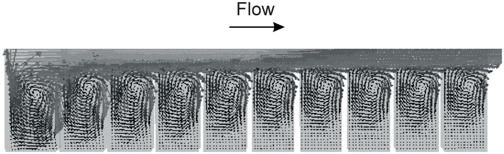
The numerical simulation was conducted using commercially available computational fluid dynamics (CFD) software, Fluent version 6.0.2, with the three-dimensional (3D) hydrodynamic single-phase model and the turbulent model. The generated vertical vortexes promote the transfer of suspended particles from the top (fast-flow region), into the quiescent settling region below. In the wastewater treatment industry, the sediments collected in many primary settling tanks are pumped from the bottom or scrapers are used to scour the bottom. Placing a virtual bed in these tanks should not affect normal operations. If the virtual bed needs to be installed in a particle-settling facility in which sediments are cleaned from the surface, the virtual bed can be mounted on a mounting frame and moved out of the way in order to access the tank bed. In this study, the focus was on assessing the performance of the proposed virtual bed, and providing test results in a laboratory setting in order to compare the relative effectiveness, instead of providing suggestions for how to use the virtual bed properly in practice.
Experimental Design and Procedures
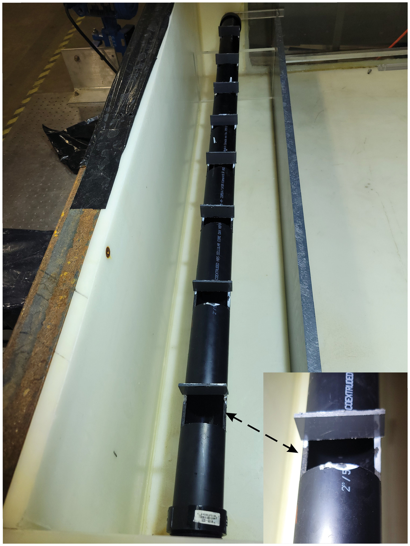
The experiments to assess the performance of the virtual bed were conducted in a () open-top settling tank. The inlet baffle and outlet height were about 24 and 26 cm above the tank bed, respectively. These experimental settings were considered to be a deeper tank (compared with subsequent experiments with an outlet height of 19 cm), with a virtual bed being mounted at two different heights (9 and 15 cm) above the tank bed. A picture of the experimental arrangements and a schematic diagram of the experimental setup are shown in Figs. 3 and 4, respectively. In order to evenly distribute the inflow into settling tank, a 5.1-cm-diameter extended inlet pipe was used to spread the flow across the width of the settling tank (Fig. 3). The bottom structure of the extension inlet pipe is shown in Fig. 5. There were multiple, evenly spaced openings along the pipe axis. At each opening, a flow-blocking baffle was placed vertically into the sidewall. The inserted length of the baffle at each opening increased gradually with the distance from the tank inlet. This balanced the flow distribution from the inlet pipe. The experimental setting was a closed-loop system, and the maximum flow rate that the water pump could provide was . During experiments, particles were released from the top of a vertical feeding pipe, about 40 cm upstream of the settling tank inlet mouth. In such an arrangement, particles should be well mixed by the incoming fast turbulent flows. After passing through the settling tank, the flow exited through a () opening located at the far end of the tank 19 or 26 cm above the tank bed depending on the experiments. Before the flow was returned to the large water supply tank, it was filtered through a 75-μm fine screen to prevent particles from returning into the circulation system. The flow then was pumped back to the settling tank via a 51-mm pipe. Between the pump and the inlet, a flow meter and a control valve were installed, the latter of which regulated the flow rates.


Because large and light particles may be more sensitive to flow conditions than smaller and heavier particles, crushed walnut shell particles (, and size range = 90–250 μm) were chosen for the experiments. This corresponded to sand particles of about 45–125 μm with a density of for an equivalent settling velocity (determined by Stokes’ law). Other advantages of using such particles included easy handling and recovery (preventing their recirculation), and good visibility (given by their characteristic brownish color), which helped to understand the flow conditions in the settling tank. To investigate the effects of the proposed virtual bed on enhancing removal of suspended particles of different sizes, the particles were sorted using sieves with mesh sizes of 90, 125, 180, and 250 μm to produce samples with three different standard and consistent size ranges (90–125, 125–180, and 180–250 μm) for the experiments. Any particles smaller than 90 μm were discarded to prevent the risk of their passing through the capture mesh. Because the density and size of walnut particles can vary slightly after they are wetted and then dried, they could be compared only against each other. Providing that the study procedure was consistent for all tests, the results should be directly comparable, even if they were not absolute. This has been confirmed by our repeatability test results, as well as by the results of other studies (He and Marsalek 2009; He et al. 2014, 2015, 2022).
In each experiment, a total of 500 g of walnut shells was used, which provided a consistent particle loading for approximately 15 min. Seed particles were prepared before each experiment by mixing (using a pitched-blade impeller mixer) 500 g crushed walnut shell powder with 4 L tap water in a container. A peristaltic sampling pump was used to draw the particle samples from the bottom of the container through 5-mm (inside diameter) flexible tubing with a flow rate of . This was fed into the path of the incoming flow by inserting the tubing into the bottom of the vertical feed pipe 40 cm upstream of the settling tank inlet. In such an arrangement, particles should be well mixed by the incoming fast turbulent flows. A mixer (with a pitched-blade impeller) was used to disturb particles in the sample container for the entire 15 min required to empty all the particles into the inlet feed. The pump continued to run for an additional 3 min, which ensured that all particles passed through or settled in the settling tank. At the conclusion of each experiment, captured particles were drained through a bottom drain (with thorough rinsing of the test tank), and collected on a 75-μm screen located below the exit of the drain pipe. The captured particles were oven-dried overnight at a temperature of 40°C (to prevent burning) and left at room temperature for 24 h before being weighed to determine their total weight. Experiments were run under well-controlled conditions. To assess the uncertainty for the experiment results, four repeat test runs were conducted with particle sizes 125–180 μm and a flow rate of ; the standard deviation of the obtained particle removal rates () was . Therefore, no duplicated runs were performed in most particle removal rate tests. In addition, pictures of the sediment distribution patterns on the settling tank bed were taken at the end of each experiment for the purpose of analyzing the particle settling behaviors and flow conditions if this was needed.
Results and Discussion
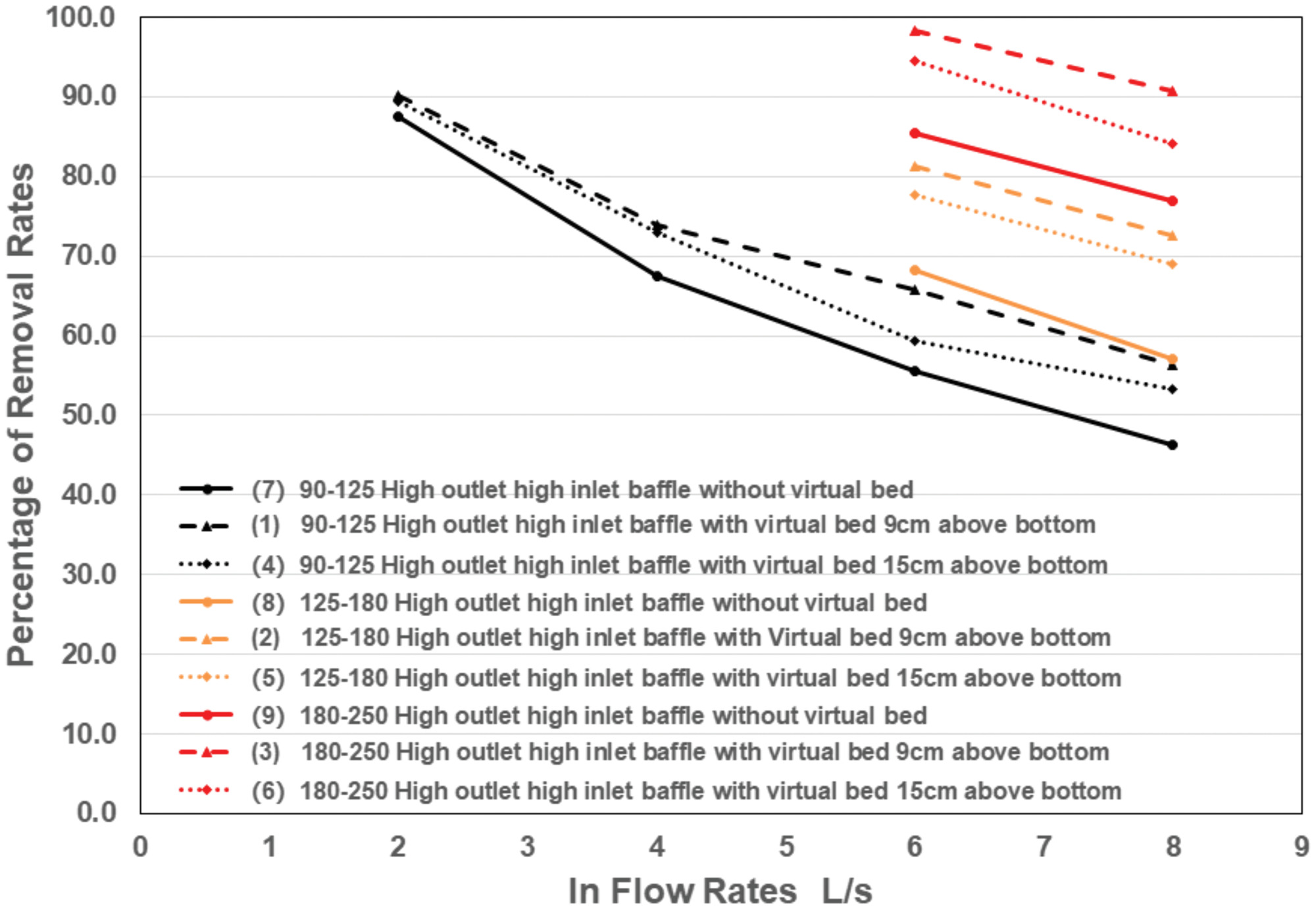
The effectiveness of the proposed virtual bed in enhancing particle settling was assessed with various experimental settings and different particle sizes and inflow rates. The first group of tests focused on investigating the influence (sensitivity) of the height of the virtual bed from the tank bed on enhancing particle settling as well as investigating the performance of the virtual bed compared with an unimproved tank bed. To make it easier to follow the experimental settings for each test, the experiments were numbered, and their settings are listed in Table 1. In the virtual bed performance comparison tests for low inflow rates, only smaller particles (90–125 μm) were used, because removing large particles under low flow rates generally is not a real issue in practice. The results are shown in Fig. 6. Comparing the particle removal rates with [Experiments 1, 2, 3, 4, 5, and 6 (dotted and dashed lines)] and without [Experiments 7, 8, and 9 (solid lines)] a virtual bed, using different inflow rates and particle sizes, shows that a virtual bed helped to capture notably more suspended particles in the testing tank. This was particularly the case under higher flow rates, at which greater advantages over the traditional gravity method were more obvious. This is a very important characteristic, because it is always challenging for gravity-based particle-settling facilities to removal smaller particles effectively under higher flow rates. Under the conditions tested, the improvement of particle removal rates was 10%–15% for all particle sizes under strong flows. In addition, the virtual beds placed 9 cm above the tank bed (Experiments 1, 2, and 3) performed better than those installed 15 cm above the tank bed (Experiments 4, 5, and 6). This suggests that the proposed virtual bed effectively could reduce erosional forces in the region of sediment accumulation. The influence of the height of the virtual bed on bottom-flow conditions was not expected to be strong. However, reduction of the top-layer water depth increased the flow speed and reduced the flow residence time, which resulted in fewer captured particles, as shown by the colored dotted lines (Experiments 4, 5, and 6) and dashed lines (Experiments 1, 2, 3) in Fig. 6. This information can serve as a useful guide for properly applying virtual beds in practice.
| Experiment | Inlet baffle height (cm) | Outlet wall height (cm) | Virtual bed height from bed (cm) | Particles sizes (μm) | Inflow rate (L/s); Reynolds number | |||
|---|---|---|---|---|---|---|---|---|
| 2; 49,950 | 4; 99,901 | 6; 149,851 | 8; 199,802 | |||||
| Removal rates (%) | ||||||||
| 1 | 24 | 26 | 9 | 90–125 | 90.10 | 73.89 | 65.79 | 56.41 |
| 2 | 24 | 26 | 9 | 125–180 | 81.31 | 72.51 | ||
| 3 | 24 | 26 | 9 | 180–250 | 98.31 | 90.78 | ||
| 4 | 24 | 26 | 15 | 90–125 | 89.41 | 72.99 | 59.40 | 53.30 |
| 5 | 24 | 26 | 15 | 125–180 | 77.67 | 69.02 | ||
| 6 | 24 | 26 | 15 | 180–250 | 94.50 | 84.18 | ||
| 7 | 24 | 26 | No VB | 90–125 | 87.55 | 67.44 | 55.63 | 46.30 |
| 8 | 24 | 26 | No VB | 125–180 | 68.16 | 57.07 | ||
| 9 | 24 | 26 | No VB | 180–250 | 85.36 | 76.98 | ||
| 10 | 24 | 19 | 9 | 90–125 | 48.74 | 44.07 | ||
| 11 | 24 | 19 | No VB | 90–125 | 48.30 | 44.00 | ||
| 12 | 17 | 19 | 9 | 90–125 | 62.89 | 50.54 | ||
| 13 | 17 | 19 | No VB | 90–125 | 50.68 | 40.62 | ||
In real-world situations, settling tanks vary greatly in depth, and this influences particle settling. To assess the influence of tank depth on the performance of the virtual bed, tests were conducted in which the outlet wall was lowered by 7 cm, the test tank depth (outlet wall height) was reduced from 26 to 19 cm, and all other experimental settings were kept the same. The intent of these tests was not to optimize the depth of the settling tank depth for the best removal performance of the virtual bed, but to investigate whether it is more effective (i.e., increased particle removal rates with versus without the virtual bed in place) to utilize a virtual bed to enhance sedimentation in a shallower tank. In general, the shallower a tank, the more turbulent the tank will be, and therefore there should be greater reduction of disturbance with the addition of a virtual bed. The test results are shown in Fig. 7. For comparison, the test results of 90–125-μm particles (Experiments 1, 4, and 7) in the deeper tank (Fig. 6) are included in Fig. 7 as black lines. In Experiment 10 (with a VB) and Experiment 11 (without a VB), both of which used 90–125-μm particles, a high inlet baffle, and a low outlet), the particle removal rates with and without a virtual bed in place were almost identical under 6- and inflow rates. In this case, the presence of the virtual bed did not enhance sedimentation.

The particle distributions retained on the testing tank bed were examined visually and compared with sediment distributions of other experiments (Fig. 8). The pictures of sediment patterns in Fig. 8 were taken at the end of each experiment (90–125-μm particles and inflow rate for each test). Fig. 8(a) shows a deeper tank, with an outlet height of 26 cm and an inlet baffle of 24 cm, with the virtual bed 9 cm above the tank bed. Fig. 8(b) shows a shallow tank, with outlet and inlet baffle heights of 19 and 24 cm, respectively, without the virtual bed. In Fig. 8(c), the test settings were the same as in Fig. 8(b) except the virtual bed was 9 cm above the tank bed. The sediment distribution patterns in Fig. 8(c) showed strong sediment ripples on the tank bottom as well as a large scoured bed area near the inlet, which is not evident in Figs. 8(a and b)]. This showed that under these particular conditions (higher inlet baffle), the virtual bed could not shield the bottom area from being disturbed by strong turbulent flows in the top layer. This resulted in varied flows below the virtual bed, and sediments were eroded periodically. The ripple-like sediment pattern in Fig. 8(c) seemly correlates well with the cell-opening pattern of the virtual bed (the grid pattern in Fig. 1, Panel N); this may indicate that strong extra flows passed through the holes of the virtual bed and entered the region below the virtual bed in the upstream area. Because the virtual bed was laid horizontally in the tank, the flows over the virtual bed must have had a strong vertical component. The inlet baffle height appeared to be of considerable importance, because it was about 5 cm higher than the height of the reduced outlet.
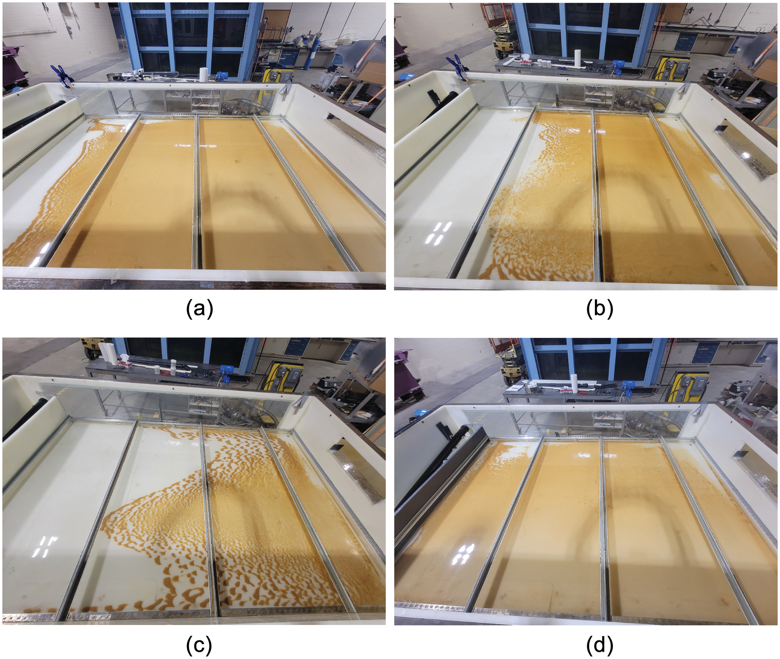
To assess the influence of the inlet baffle height, experiments were carried out with the inlet baffle height decreased by 7 cm (the new inlet baffle height was 17 cm). The settled particle distribution pattern on the tank bed is displayed in Fig. 8(d). The wave ripple patterns in Fig. 8(c) disappeared in Fig. 8(d), and the sediment pattern on the tank bed was more evenly distributed; even the area close to the inlet was covered with settled particles. With this simple modification, the virtual bed performance was greatly improved [compare the results for Experiments 12 (red dashed line) and 10 (brown solid line) in Fig. 7]. In this way, the functionality of the tank was greatly improved. The virtual bed created a well-protected bottom region to encourage particle settling and prevent settled particles from being resuspended. These testing results clearly show that in order to make virtual bed work more effectively, the inlet baffle should be kept low relative to the outlet height in order to direct flows in the region above the virtual bed more horizontally or slightly upward. The virtual bed in the shallower tank [Experiments 12 (Fig. 7, dashed red line) and 13 (solid red line)] performed slightly better in terms of increased particle removal rates than in a deeper tank [Experiments 1 (Fig. 7, dashed black line) and 7 (Fig. 7, solid black line)]. These results verified the hypothesis that the virtual bed should be more effective in a shallower tank, in terms of percentage particle removal rates, than in a deeper tank. This is true even though the total particle removal rates in a deeper tank were higher than in a shallow tank (Fig. 7, black and red lines).
To enhance settling further, several new designs of the virtual bed cell structure were investigated. Partially blocking the cell opening of the virtual bed or changing the geometry of the virtual bed cell to encourage the flows above the virtual bed moving in a horizontal direction and increase hydraulic resistance generated by the virtual bed cells to further reduce the possibilities of the upper flow entering the lower area were investigated. Four additional virtual bed structure designs were tested (Fig. 1, Designs A–D). To save resources, all tests of the virtual bed structures’ effects on particle removal rates were conducted only in a shallow tank. Similar performance results are expected in deeper tanks because the functionalities of the virtual bed and all other physical processing in a deeper tank are very similar to those in a shallow tank. Virtual bed designs A and B reduce the cell openings by 50% by blocking every other row (Design A) or cell (Design B). Designs C and D have sloped cell walls; Design C has a sloped wall on only one side, and Design D has sloped walls on all sides. The purpose of these design patterns was to slow the flows into the cell, without generating measurably negative effects on the particles falling into the area below the virtual bed. The potential designs for such a virtual bed structure could be quite far-ranging. The main purpose of the tests was to investigate how changes to the virtual bed cell structure designs and virtual bed arrangements could influence particle removal rates, and to search for creative ways to improve the effectiveness of particle removal further. All tests were conducted in the shallow tank using the newly modified virtual bed structures (Fig. 1, Designs A–D) for the first two rows (most upstream) of the virtual bed, and rest of the virtual bed was covered with the normal virtual bed structure (Fig. 1, Design N). The individual experimental settings and results are listed in Table 2. As before, only particles with sizes of 90–125 μm were used in these tests because the smaller particles were more sensitive to the flow conditions and were more challenging to remove. Experiment 14 in Table 2 used Design C (Fig. 1) with the wall sloped downward with the flow direction. These panels occupied the first two rows (approximately 60% of the total virtual bed). This combination performed worse than the virtual bed using only the normal panels, i.e., Design N (Experiment 1). It is possible that because the slope of the wall was on the upstream side, it encouraged too much flow to enter the lower area, which would disturb the particle settling. To conserve mass, any flows that enter must have a corresponding flow that returns to the surface level. This would increase the opportunities for particles to re-enter the strong turbulent flow area in the upper level. This also would further reduce the chances of particles settling below the virtual bed, and thus lead to more particles escaping the settling tank.
| Experiment | Experimental settings | Inflow rate (L/s) | |||||
|---|---|---|---|---|---|---|---|
| Positions of outlet and inlet baffles | Configuration of VB | ||||||
| Row 1 | Row 2 | Row 3 | Row 4 | 6 | 8 | ||
| Removal rate (%) | |||||||
| 14 | Low outlet, low inlet | Slope reversed (C) | Slope reversed (C) | Normal | Normal | 59.92 | 48.4 |
| 15 | 50% reduced (A) | 50% reduced (A) | Normal | Normal | 62.95 | 51.71 | |
| 16 | Altered (B) | Sloped (C) | Normal | Normal | 63.18 | 52.39 | |
| 17 | Sloped (C) | Sloped (C) | Normal | Normal | 64.95 | 58.16 | |
| 18 | All cell sides sloped (D) | All sides cell sides sloped (D) | Normal | Normal | 63.73 | 53.22 | |
| 19 | Normal | Normal | — | — | 56.59 | 47.79 | |
Note: A–D indicate different altered virtual bed designs.
In Experiment 15 (Table 2), the first two rows of the virtual bed had cell the opening pattern reduced by 50% using Design A. Experiment 16 in Table 2 used Design patterns B and C as the first and second rows, respectively. Pattern B is an alternative way to reduce 50% of the cell openings. This test used a different arrangement of Pattern C than Experiment 14: Design C virtual bed panels were rotated 180° so that the slope of the wall was upward in the flow direction. The results from these two new tests were very similar to each other (Table 2) and to the performance of the normal virtual bed (Table 1, Experiment 1). The results showed that by blocking the cell opening, flows to the settling region under the virtual bed are restricted, but the chances of particles entering underneath the virtual bed were also reduced. Overall, the results suggest that applying Variations A and B in the tested configurations did not significantly differ from using the normal virtual bed. A further test with two rows of Pattern C followed by two rows of the normal virtual bed was carried out (Table 2, Experiment 17). In this test, both Pattern C panels were arranged with the slope facing upstream. The purpose of this arrangement was to force flows to make a greater-than-90° turn in order to pass through the Virtual bed pattern C; this could greatly increase the flow hydraulic resistance for flows passing through the cells of the virtual bed into the quiescent zone below the virtual bed. This restriction should not have a strong influence on particles passing through the virtual bed. The particle removal rates (Table 2, Experiment 17) increased noticeably compared with those of the other tested virtual bed structure patterns and settings. The performance should be greatly improved if the whole settling tank bed were to be covered with a Design C virtual bed. Experiment 18 in Table 2 tested Design pattern D, which has sloped walls on all four sides of the cell. Because the top opening of the cells is larger than the bottom opening, it is more difficult for the flows to pass through. The particle removal rates were better than those using the normal virtual bed. However, compared with Design C, the angle at which flows turn as they pass through the virtual bed cell was smaller, which led to less flow hydraulic resistance and therefore slightly worse particle removal rates.
The preceding testing results show that different designs of the virtual bed structure can have a strong influence on the performance. The results also show that increasing the hydraulic resistance to flow passage and thus reducing flows entering the quiescent zone below is a good basis for virtual bed design to achieve higher particle removal rates. All the tests conducted with the virtual bed (and modifications) used high flow rates and small, light particles. Under these more-turbulent flow conditions, the results clearly showed that a virtual bed was able to improve the particle-settling tank performance consistently, and this makes it distinct from many other sedimentation enhancement methods.
In most particle-settling facilities, flows near the inlet areas are more turbulent than those in downstream areas because the flow kinetic energy gradually becomes dispersed moving away from the inlet through friction and heat losses. Placing a layer of the virtual bed near the inlet region may be more effective in terms of enhancing particle settling than placing the virtual bed in areas located downstream, because the flow conditions downstream may not need improving. The virtual bed could be deployed in targeted areas to improve particle removal results and save costs. To verify this assumption, additional experiments were conducted (Table 2, Experiment 19). The results indicated that at a higher flow rate of , the virtual bed with only two rows was more effective in enhancing particle settling in terms of the improved particle removal percentages than at a lower inflow rate of . At high flow rates, more-turbulent flows need to be conditioned by the virtual bed to reduce their negative effects on particle settling. Using only two rows of virtual bed in the settling tank improved particle removal rates by 7%–9%, compared with 10%–13% with the bed fully covered. In practice, this suggests that the virtual bed should be deployed in areas with the most turbulent and strongest flows.
Conclusions
A virtual bed concept is proposed, and five different structural designs were tested in a very well-controlled experimental setting with varying particle sizes and flow rates; the normal element of the proposed virtual bed structure is a flat plate with many vertical through holes on it. The virtual bed is a layer which can be placed at varying heights and configurations above the original solid bed. The virtual bed’s principle of enhancing sedimentation is based on (1) insulating the bottom area from being disturbed by strong flows occurring in the top layer; and (2) utilizing the vertical vortex, generated by incoming flows, within the virtual bed cells to create more opportunities for particles to transfer from the top layer to the bottom layer. The testing results clearly showed that a simple layer of the virtual bed greatly increased the performance of a particle-settling tank. The improvements were more obvious under high flow rates and for small particles. The ability to remove small particles at high flow rates, without chemical addition, is crucial for primary treatment of wastewater, stormwater runoff, and combined sewage overflow, because it not only is difficult to achieve, but also is well-known that smaller particles often carry the majority of pollution. This characteristic makes the virtual bed stand out from many other particle-removal technologies. The testing results also showed that varying the geometric shapes of the virtual bed cells could have a strong influence on the effectiveness of the virtual bed. Of the five virtual bed structures tested, the structure with the wall slope pointing upward in the flow direction performed best. One important advantage of the virtual bed is that it effectively can reduce the influence of strong turbulent flows at the inlet; applications should prioritize the deployment of the virtual bed in areas with strong turbulent flows. Although this study was conducted in a laboratory with a particular experimental settling tank, which can be very different in terms of the physical structure and flow conditions from facilities used in practice, the principle of virtual bed enhancing particle settling should be applicable to particle-separation facilities with different configurations. Developing a general formula that can describe quantitatively the performance of the virtual bed based on this study’s settings and results was outside of the scope of this paper. The next study will focus on designing more-effective virtual bed structures, based on the knowledge obtained in this study of the concept verification of virtual beds. These new designs will include the shape of the opening, the thickness of the virtual bed plate, and the slope angle of the opening wall, among others. Because they are all dependent on flow conditions, there may never be a “best design pattern” for all circumstances.
Data Availability Statement
All data, models, or code that support the findings of this study are available from the corresponding author upon reasonable request.
Acknowledgments
This study was financially supported by the Great Lakes Action Plan (GLAP) with funding by Environment and Climate Change Canada. Thanks are offered for the support from the Engineering Branch at the National Water Research Institute for providing very valuable advice and helping to build the physical model.
References
Andoh, R. Y. G., S. P. Hides, and A. J. Saul. 2002. “Improving water quality using hydrodynamic vortex separators and screening systems.” In Proc., 9th Int. Conf. on Urban Drainage. Portland, OR: International Water Association.
Banerjee, A., R. K. Calay, and F. E. Eregno. 2022. “Role and important properties of a membrane with its recent advancement in a microbial fuel cell.” Energies 15 (2): 444. https://doi.org/10.3390/en15020444.
Brooke, J. W., K. Kontomaris, T. J. Hanratty, and J. B. McLaughlin. 1992. “Turbulent deposition and trapping of aerosols at a wall.” Phys. Fluids A 4 (4): 825–834. https://doi.org/10.1063/1.858299.
Caporaloni, M., F. Tampieri, F. Trombetti, and O. Vittori. 1975. “Transfer of particles in nonisotropic air turbulence.” J. Atmos. Sci. 32 (3): 565–568. https://doi.org/10.1175/1520-0469(1975)032%3C0565:TOPINA%3E2.0.CO;2.
Cuthbertson, A. J. S., D. A. Ervine, T. B. Hoey, and O. Heinrich. 1998. “Settling characteristics of fine grained sediments in turbulent open channel flow.” In Proc., 3rd Int. Conf. on Hydroscience and Engineering. Chicago: World Academy of Science, Engineering and Technology.
Eaton, J. K., and J. R. Fessler. 1994. “Preferential concentration of particles by turbulence.” Int. J. Multiphase Flow 20 (Mar): 169–209. https://doi.org/10.1016/0301-9322(94)90072-8.
Eregno, F. E., and A. Heistad. 2019. “On-site treated wastewater disposal systems—The role of stratified filter medias for reducing the risk of pollution.” Environ. Int. 124 (Mar): 302–311. https://doi.org/10.1016/j.envint.2019.01.008.
Gibson, T. F., W. O. Watanabe, T. M. Losordo, R. F. Whitehead, and P. M. Carroll. 2020. “Evaluation of chemical polymers as coagulation aids to remove suspended solids from marine finfish recirculating aquaculture system discharge using a geotextile bag.” Aquacultural Eng. 90 (Aug): 102065. https://doi.org/10.1016/j.aquaeng.2020.102065.
He, C., P. Chittibabu, D. Nguyen, and Q. Rochfort. 2022. “Investigating effectiveness of vortex enhancing particles settling in a hydraulic separator with physical modeling.” J. Environ. Eng. 148 (6): 04022027. https://doi.org/10.1061/(ASCE)EE.1943-7870.0002004.
He, C., and J. Marsalek. 2009. “Vortex plate for enhancing particle settling.” J. Environ. Eng. 135 (8): 627–635. https://doi.org/10.1061/(ASCE)EE.1943-7870.0000024.
He, C., Q. Rochfort, and R. McFadyen. 2014. “Potential errors and error propagation in methods used to determine particle removal efficiency.” J. Environ. Eng. 140 (6): 21–29. https://doi.org/10.1061/(ASCE)EE.1943-7870.0000839.
He, C., E. Scott, and Q. Rochfort. 2015. “Enhancing sedimentation by improving flow conditions using parallel retrofit baffles.” J. Environ. Manage. 160 (Sep): 1–6. https://doi.org/10.1016/j.jenvman.2015.06.013.
Kiringu, K., and G. Basson. 2020. “Factors influencing the removal of fine non-cohesive sediment by vortex settling basin at small river abstraction works.” Int. J. Sediment. Res. 36 (4): 501–511. https://doi.org/10.1016/j.ijsrc.2020.12.004.
Marchioli, C., and A. Soldati. 2002. “Mechanisms for particle transfer and segregation in a turbulent boundary layer.” J. Fluid Mech. 468 (Oct): 283–315. https://doi.org/10.1017/S0022112002001738.
McLaughlin, J. B. 1998. “Aerosol particle deposition in numerically simulated channel flow.” Phys. Fluids 1 (7): 1211–1224. https://doi.org/10.1063/1.857344.
Nelson, C. H., K. R. Johnson, and J. H. Barber. 1987. “Gray whale and walrus feeding excavation on the Bering shelf, Alaska.” J. Sediment. Res. 57 (3): 419–430. https://doi.org/10.1306/212F8B4D-2B24-11D7-8648000102C1865D.
Pan, K. Y., and S. Banerjee. 1996. “Numerical simulation of particle interactions with wall turbulence.” Phys. Fluids 8 (10): 2733–2755. https://doi.org/10.1063/1.869059.
Pedinotti, S., G. Mariotti, and S. Banerjee. 1992. “Direct numerical simulation of particle behavior in the wall region of turbulent flow in horizontal channels.” Int. J. Multiphase Flow 18 (6): 927–941. https://doi.org/10.1016/0301-9322(92)90068-R.
Peng, W., A. C. Hoffmann, H. W. A. Dries, M. A. Regelink, and L. E. Stein. 2005. “Experimental study of the vortex end in centrifugal separators: The nature of the vortex end.” Chem. Eng. Sci. 60 (24): 6919–6928. https://doi.org/10.1016/j.ces.2005.06.009.
Reeks, M. W. 1983. “The transport of discrete particles in inhomogeneous turbulence.” J. Aerosol Sci. 14 (6): 729–739. https://doi.org/10.1016/0021-8502(83)90055-1.
Risk, M. J., and H. D. Craig. 1976. “Flatfish feeding traces in Minas Basin.” J. Sediment. Res. 46 (2): 411–413. https://doi.org/10.1306/212F6F82-2B24-11D7-8648000102C1865D.
Sabbagh, R., M. G. Lipsett, C. R. Koch, and D. S. Nobes. 2015. “Hydrocyclone performance and energy consumption prediction: A comparison with other centrifugal separators.” Sep. Sci. Technol. 50 (6): 788–801. https://doi.org/10.1080/01496395.2014.978463.
Yager, P. L., A. R. M. Nowell, and P. A. Jumars. 1993. “Enhanced deposition to pits: A local food source for benthos.” J. Mar. Res. 51 (1): 209–236.
Yu, J. H., H. X. Yu, and L. Q. Xu. 2013. “Performance evaluation of various stormwater best management practices.” Environ. Sci. Pollut. Res. 20 (9): 6160–6171. https://doi.org/10.1007/s11356-013-1655-4.
Information & Authors
Information
Published In

Journal of Environmental Engineering
Volume 150 • Issue 4 • April 2024
Copyright
This work is made available under the terms of the Creative Commons Attribution 4.0 International license, https://creativecommons.org/licenses/by/4.0/.
History
Received: Jan 9, 2023
Accepted: Nov 9, 2023
Published online: Jan 27, 2024
Published in print: Apr 1, 2024
Discussion open until: Jun 27, 2024
ASCE Technical Topics:
- Bed materials
- Chemical treatment
- Cooling (wastewater treatment)
- Engineering fundamentals
- Engineering materials (by type)
- Environmental engineering
- Equipment and machinery
- Flow (fluid dynamics)
- Fluid dynamics
- Fluid mechanics
- Hydrologic engineering
- Inflow
- Materials engineering
- Particles
- River and stream beds
- River engineering
- Rivers and streams
- Sediment
- Sedimentation tanks
- Tanks (by type)
- Turbulent flow
- Waste management
- Waste treatment
- Water and water resources
- Water treatment
- Water treatment plants
Authors
Metrics & Citations
Metrics
Citations
Download citation
If you have the appropriate software installed, you can download article citation data to the citation manager of your choice. Simply select your manager software from the list below and click Download.