An Alternative Approach to Dynamic Earth Pressure Coefficients to Improve the Seismic Limit State Design of Earth-Retaining Structures
Publication: Journal of Geotechnical and Geoenvironmental Engineering
Volume 150, Issue 10
Abstract
Dynamic earth pressure coefficients are widely used in the seismic engineering design of earth-retaining structures. Nevertheless, there remains confusion about their validity, with past studies conflictingly arguing the same estimates can be either conservative or unconservative. This study aims to address past uncertainty surrounding the limiting dynamic stress state in retained soil. Dynamic centrifuge testing and complementary numerical analyses are used to support a simpler, more fundamental interpretation of the dynamic limiting stress state of retained soil. The case of a dry, cohesionless, and level soil bed retained by smooth walls experiencing seismic loading is used to clarify the underlying mechanics that are relevant for a broad range of engineering problems with retained soil. Ultimately, the findings can promote a move away from previous methods to estimate dynamic earth pressure coefficients. Instead, it is shown that Rankine earth pressure coefficients can be combined with the newly discovered dynamic normal vertical effective stresses to better define the limiting stress state of soils under seismic loading. These vertical dynamic variations are attributed to soil rocking that is a function of the wall-soil interface properties and system dynamics and can be induced by purely horizontal shaking. Finally, simplified analytical methods to estimate the distribution and time histories of dynamic normal vertical effective stresses are proposed. Validation of these against the numerical predictions illustrates a more theoretically sound path forward to estimate the limiting horizontal stresses, and thus forces, for the improved seismic limit state design of earth-retaining structures.
Introduction
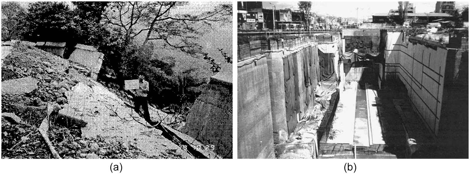
There are numerous examples of soil-retaining systems performing poorly under earthquake loading e.g., Taiwan 1999 or Niigata 2004. Catastrophic collapses can be more likely for saturated conditions such as quay-walls retaining and/or founded in loose, cohesionless soils, e.g., Kobe 1995 (Dewoolkar et al. 2001; Dakoulas and Gazetas 2008). Equally, there are many examples of wall systems being resilient to large seismic actions, e.g., Loma Prieta 1989, Northridge 1994, Athens 1999, and Kocaeli 1999 (Gazetas et al. 2005; Youd et al. 2000; Lew et al. 1995; Mikola and Sitar 2013). Fig. 1 illustrates this contrast.
Nevertheless, the fundamental dynamic interaction between the retaining wall and soil remains poorly understood (Gazetas et al. 2004), with Kramer (1996) noting that “the dynamic response of even the simplest type of retaining wall is quite complex.” This has historically motivated simplified design methodologies to predict limiting dynamic forces. However, the same methods have been criticized for being both under- and over-conservative, and hence there has been a longstanding uncertainty over their validity.
This study revisits the assumptions that are made by many widely used design methodologies and suggests a new interpretation of the dynamic response of retained soil under horizontal shaking. For simplicity, the response of a dry, cohesionless, coarse-grained material retained by smooth vertical walls experiencing horizontal shaking is considered, though the fundamental results are more generally applicable. For example, the dynamic forces induced by retained soil are also relevant to the design of buried reservoirs and basements. It is hypothesized that the cyclic shear stresses from purely horizontal shaking can induce dynamic normal effective stresses both horizontally and vertically within retained soil. While these have been previously ignored, recognition of these dynamic normal vertical effective stresses when interpreting the dynamic stress state could help resolve the seemingly contradictory findings in past research that has contributed to the confusion among design professionals and academicians alike. The hypothesis is tested with dynamic centrifuge tests and complementary numerical analyses. Finally, a path forward to straightforwardly predict the limiting dynamic stresses states, and thus forces, experienced by structures that retain soil experiencing dynamic loads, is discussed.
Design Methodologies and Uncertainties
Pseudostatic analyses have been a prevailing design methodology in industry to establish limiting dynamic forces (e.g. Eurocode EC7, EC8, US NCHRP, FEMA-NEHRP or AASHTO LRFD). Often referred to as the Mononobe-Okabe (MO) method (Okabe 1924; Mononobe and Matsuo 1929), the analysis extends Coulomb’s (1776) limiting static earth pressure coefficients and ultimately is equivalent to a rigid-plastic upper bound estimate for smooth walls (Collins 1973). Inertial forces acting on an active or passive soil wedge are assumed in deriving the limiting dynamic forces. Extensions include estimating the point of action of the seismic forces (Seed and Whitman 1970), assuming nonplanar failure surfaces (Chen and Liu 1990), and pseudodynamic predictions approximating the effect of the phase lag of the horizontal accelerations on the dynamic forces (Steedman and Zeng 1990). As a derivative of Coulomb’s (1776) work, MO methods only predict the limiting forces that can develop between the wall and soil for an instantaneous inertial force, assuming a yielding (i.e., displacing) wall and rigid-plastic soil behavior.
Scott (1973) argued that the seismic pressures that develop prior to any wall displacement dictate the ensuing dynamic behavior. Elastic predictions of soil stresses adjacent to a nonyielding wall, e.g., Wood (1975), are typically higher than the limiting active MO values. Scott (1973) suggested that these pressures drive the initial displacement of yielding walls, though Wood’s (1975) solutions are generally applied to restrained or nonyielding cases such as basement walls. Veletsos and Younan (1994, 1995, 1997, 2000) present analytical solutions to predict the lateral soil pressures on rigid and flexible cantilever retaining walls, modeling the problem with a seminfinite viscoelastic soil layer bonded to a rigid base and an elastic wall section with a rotational spring at its base. Modal analysis can then predict the dynamic response under both harmonic and realistic base motions.
Analytical elastic/viscoelastic approaches do not generally bound the predicted stress states with a strength failure criterion. Further, the larger dynamic active pressures predicted by some of these methods, potentially two to three times greater than the MO active predictions, lack validation from experiments or case histories. A more subtle limitation of early studies utilizing this approach, stated in Veletsos and Younan (2000), is the assumption of no vertical normal stress or variation of vertical displacements across the semi-infinite soil layer, discussed further in the next section. While more recent elastodynamic studies have removed this limitation (e.g., Garcia-Suarez and Asimaki 2020; Garcia-Suarez et al. 2021), the assumption of elastic soil behavior remains. Thus, the findings may not be applicable where there is sufficient relative displacement between the wall and soil (i.e., caused by wall movement, soil movement, or both) to cause plastic strains.
The divergent approaches to modeling the dynamic response of retaining walls were noted by Nadim and Whitman (1983) and Al-Homoud and Whitman (1995) who combined viscoelastic wave propagation with plastic failure on a slip surface using finite element analyses. Analytically, Veletsos and Younan (1997) predicted horizontal dynamic elastic pulses proportional to the structural flexibility and rotational stiffness of the wall base, i.e., elastic predictions for more compliant systems reduce toward the MO limits. This potential convergence is also demonstrated by Psarropoulos et al.’s (2005) viscoelastic finite element analyses and Brandenberg et al.’s (2015) analytical kinematic framework; both predict a reduction of the dynamic stresses with increasing wall rotation and/or translation.
Past studies have investigated both the definition of the limiting state of retained soil under dynamic loading and the comparison of mobilized stresses to these limit states. The limiting stress state is relevant for design professionals as it establishes the limiting seismic forces an earth-retaining structure can attract, e.g., for Ultimate Limit State (ULS) Factor of Safety calculations. At present, there remains uncertainty about whether plastic MO style approaches define the limiting state of retained soil under dynamic loading (i.e., the lowest and highest horizontal effective stresses) or whether these bounds do not apply depending on the wall displacement i.e., as suggested by some elastic approaches that do not enforce a shear failure criterion for the soil. In the latter case, the scope for soil to plastically strain when driven away from or against a nonyielding wall could be missed. This is a separate consideration to whether these limit states are fully mobilized for a given seismic load and soil-retaining system (Bolton and Steedman 1982; Lew et al. 2010; Khokher and Madabhushi 2010; Al Atik and Sitar 2010; Hushmand et al. 2014). Methods that aim to predict seismic wall displacements [e.g., Elms and Richards’ (1979) method based on Newmark (1965)], are also not relevant to clarifying the dynamic limit states of retained soil and thus not discussed further.
Predicting the limiting horizontal dynamic forces the soil can exert must be distinguished from predicting the limiting dynamic horizontal effective stresses. It is noted that the original MO method was derived in terms of limiting seismic forces. However, it is commonly used, as the name implies, to obtain dynamic earth pressure coefficients by linking the limiting dynamic horizontal effective stress to the geostatic vertical effective stresses. The present study highlights that this, and the subsequent conclusions for static versus dynamic retained soil behavior, can be erroneous.
Static versus Dynamic Earth Pressure Coefficients
Equivalent static earth pressure coefficients can be derived with upper and lower bound plasticity solutions (Chen and Liu 1990; Drucker et al. 1952), i.e., the true solution is found that simultaneously satisfies equilibrium, compatibility, and the perfectly plastic failure criterion. For a level soil body whose failure can be characterized by a single, macroscopic drained friction angle (), Rankine (1856) coefficients can be obtained by finding the limiting major () to minor () principal effective stress ratio, i.e., the largest Mohr’s circle of stress that can fit within the Mohr-Coulomb failure surface for a cohesionless soil as given in Eq. (1)
(1)
Eq. (1) is often described as being equivalent to Coulomb’s earth pressure coefficient solution for the case of a vertical, smooth wall. However, bearing the derivation in mind, it is evident that the limiting principal effective stress ratio within the soil must always be given by Eq. (1). Differing lateral earth pressure coefficients for the same material assumptions (e.g., Coulomb’s (1776) or Breslau-Müller (1906) coefficients for rough, inclined walls) cannot be interpreted as defining the limiting ratio of major to minor principal effective stress, but instead are trying to capture the ratio of horizontal to (geostatic) vertical normal effective stresses. For example, kinematic constraints or interfacial shear stresses can result in soil arching, where the vertical effective stresses adjacent to a retaining system are typically reduced with respect to the geostatic values (Michalowski and Park 2003; Paik and Salgado 2003; Khosravi et al. 2016). However, methods that recover the minor principal effective stress should then use Eq. (1) to find the major principal effective stress for soil at plastic failure.
Dynamic earth pressure coefficients can be derived from predicted dynamic forces by assuming geostatic vertical effective stress distribution for the total force, or an inverted triangular distribution for the dynamic increment (Seed and Whitman 1970). This necessarily predicts linear distributions of the limiting dynamic horizontal effective stresses. While dynamic earth pressure coefficients define the ratio of horizontal to vertical effective stress, this is identical to the principal effective stress ratio for smooth wall-backfill interfaces. MO approaches and similar that include the wall-soil friction angle imply that the limiting earth pressure coefficients during dynamic loading is different to the static case. However, the present study emphasizes that Eq. (1) must also hold during dynamic loading as seismic action will not change the major to minor principal effective stress ratio that can cause failure in the material.
In this regard, dynamic earth pressure coefficients are quite different to static earth pressure coefficients. The latter can be interpreted as a material constant while the former combines external loading with a measure of the material strength. Active dynamic earth pressure coefficients greater than the static active value could be due to the locally experienced acceleration, partial mobilization of the soil strength, or a combination of the two. However, dynamic earth pressure coefficients obtained by incorrectly assuming geostatic vertical stresses adds additional scope for confusion when defining the limiting stresses earth-retaining systems will experience. Table 1 lists examples of past studies that interpreted or used dynamic earth pressure coefficients in this way. The list of experimental studies focuses on dynamic centrifuge data for experiments featuring dry soil, simple geometries, and soil-wall interfaces that are reasonably smooth. Illustrative numerical or analytical approaches with similar modeling assumptions are also listed. The interpretation of the dynamic stress states in this way is particularly surprising for numerical studies where there is no need to assume the vertical effective stress distributions. In fact, the majority of plasticity-based soil constitutive laws enforce Eq. (1) as the limiting principal effective stress ratio for both static and dynamic analyses (returned to in §Elastic Soil Behavior, Pulses and Hypothesis).
| Methodology | Study | Interprets and/or uses limiting dynamic earth pressure coefficients as a ratio of stresses (rather than forces) by assuming geostatic vertical stresses | Measures or predicts pressures smaller than MO active or larger than MO passive states | Measures or predicts pressures larger than MO active and smaller than MO passive states |
|---|---|---|---|---|
| Experimental studies | Ortiz et al. (1983) | ✓ | ✓ | ✓ |
| Steedman and Zeng (1990) | ✓ | ✓ | ✓ | |
| Dewoolkar et al. (1995) | ✓ | ✓ | × | |
| Nakamura (2006) | ✓ | ✓ | ✓ | |
| Al-Atik and Sitar (2009) | ✓ | ✓ | × | |
| Khokher and Madabhushi (2010) | ✓ | ✓ | ✓ | |
| Athanasopoulos et al. (2012) | ✓ | ✓ | ✓ | |
| Geraili Mikola et al. (2016) | ✓ | ✓ | ✓ | |
| Jo et al. (2017) | ✓ | ✓ | ✓ | |
| Numerical and/or analytical studies | Wood (1973) | ✓ | ✓ | ✓ |
| Scott (1973) | ✓ | × | ✓ | |
| Veletsos and Younan (1994) | × | ✓ | ✓ | |
| Green et al. (2003) | ✓ | ✓ | ✓ | |
| Gazetas et al. (2004) | ✓ | ✓ | ✓ | |
| Ostadan (2005) | ✓ | × | ✓ | |
| Psarropoulos et al. (2005) | ✓ | ✓ | ✓ | |
| Mylonakis et al. (2007) | ✓ | ✓ | × | |
| Al Atik and Sitar (2010) | ✓ | ✓ | ✓ | |
| Kloukinas et al. (2012) | × | ✓ | ✓ | |
| Athanasopoulos et al. (2013) | ✓ | ✓ | ✓ | |
| Brandenberg et al. (2015) | ✓ | ✓ | ✓ | |
| Garcia-Suarez and Asimaki (2020) | × | ✓ | ✓ | |
| Deng et al. (2022) | ✓ | ✓ | ✓ |
Note: In most cases, the potential for dynamic normal vertical effective stresses is explicitly or implicitly ignored, potentially confusing the interpretation of the mobilized and/or limiting dynamic earth pressures.
Table 1 also indicates whether the study found dynamic stress states within or outside the pseudostatic predictions. Overall, this is used to demonstrate the significant uncertainty that surrounds the predictions obtained by conventional dynamic earth pressure coefficients that did not capture the limiting stresses. Past studies have used these observations to motivate different predictions for mobilized or limiting dynamic earth pressure coefficients. However, when applied to limiting soil stresses this can cause confusion, especially when the lateral earth pressure coefficient and limiting principal effective stress ratio must be equivalent, e.g., at smooth soil-wall interfaces. Further, it is theorized that past findings that support different limiting dynamic earth pressure coefficients did not consider that under dynamic loading both the major and minor principal effective stresses could vary. It is also noted that comparisons of the inferred or predicted earth pressure coefficients implied by the horizontal effective stresses to Eq. (1) during dynamic loading were seldom made.
The Existence of Dynamic Normal Vertical Effective Stresses in Retained Soil Experiencing Horizontal Shaking
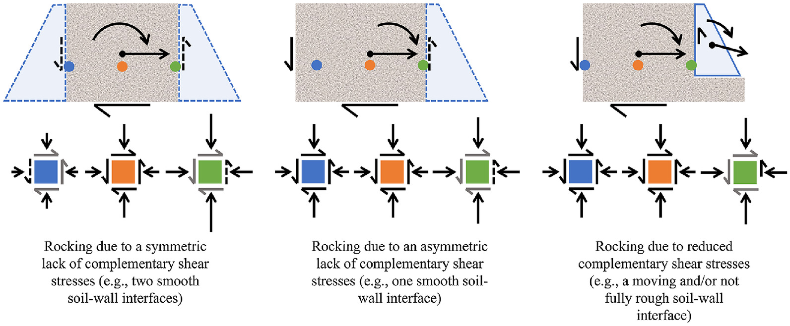
Madabhushi (2018) and Madabhushi and Haigh (2021a, b) combined dynamic centrifuge tests and numerical analyses that revealed dynamic normal vertical effective stresses generated by horizontal shaking within the dry sand retained between two rows of parallel sheet pile walls tied at their heads. In this study, the descriptor “normal” is used to distinguish the stress component from shear stresses while horizontal versus vertical is used to indicate the direction. Fig. 2 shows increases of up to 100% of the geostatic values are numerically predicted for the sinusoidal PGA horizontal input motion. The general rocking mechanics that can justify these variations for rough and smooth walled systems are also illustrated. The rocking that develops either from wall friction or reduced complementary shear stresses are described as relevant for dynamic stress variations in the soil outside the dual row system and thus for retained soil more generally.
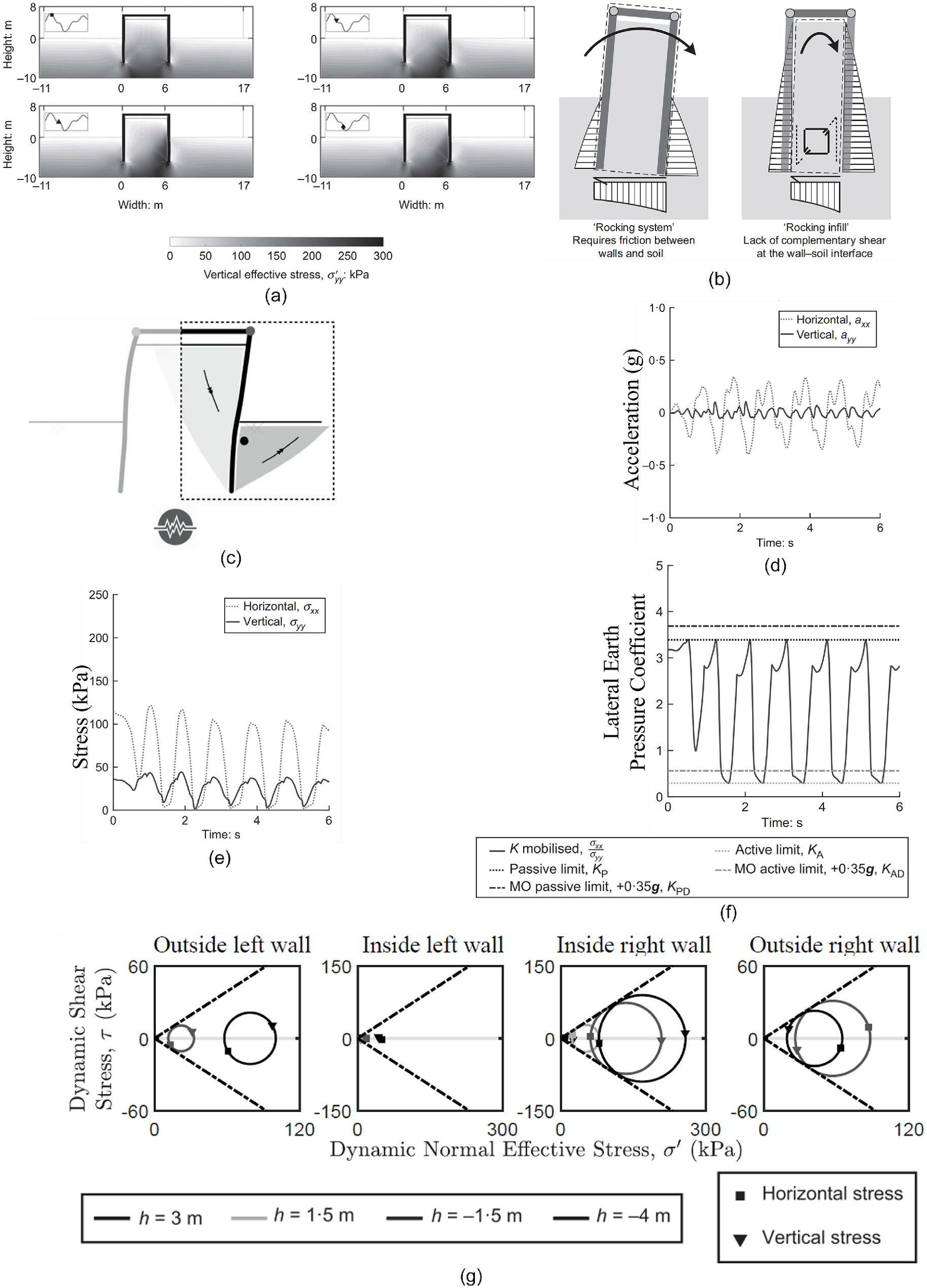
The retained and excavated sides of one half the dual row wall system can be compared to a single anchored cantilever wall. Focusing on the excavated side, the kinematics of the passive wedge gives a peak vertical acceleration of , i.e., a vertical stress change of 10% the static value, that can partially explain the observed stresses. Fig. 2 also presents the mobilized earth pressure coefficient. Calculated as the ratio of horizontal to vertical effective stresses, it approaches the ratio of principal effective stresses even for moderate shear stresses. For example, given a shear stress, , equal to 20% of the major principal effective stress, , and under passive conditions (e.g., ), Eq. (2) derived from a Mohr’s circle of stress shows that the horizontal effective stress, , will be the major principal effective stress value
(2)
With this in mind, the time history of the predicted mobilized earth pressure coefficient in Fig. 2 is observed to be bounded by the static earth pressure coefficients but not the MO coefficients. This is further exemplified by the predicted dynamic Mohr’s circles of stress remaining within the Mohr-Coulomb failure criterion.
Elastic Soil Behavior, Pulses, and Hypothesis
The mechanical consistency between the measured and predicted dynamic response of the dual row retaining walls increased the confidence in the dynamic vertical effective stresses that were numerically predicted but not measured. However, the observation that the dynamic stress state is bounded by the Mohr-Coulomb envelope was necessitated by the soil constitutive model used. Elastoplastic constitutive laws typically enforce the Mohr-Coulomb failure criteria independent of strain and hence elastic stress pulses that exceed this plastic limit cannot be predicted.
The theoretical limiting plane-strain stress states that a small volume of soil can exhibit are explored in Fig. 3. Statically, uniaxial loading of soil confined within a perfectly rigid container could realize principal effective stress ratios that exceed depending on the Poisson ratio, , if the soil remains elastic and the homogeneous continuum assumption holds. However, if the boundaries are not fixed, plastic soil failure within an active zone is expected.
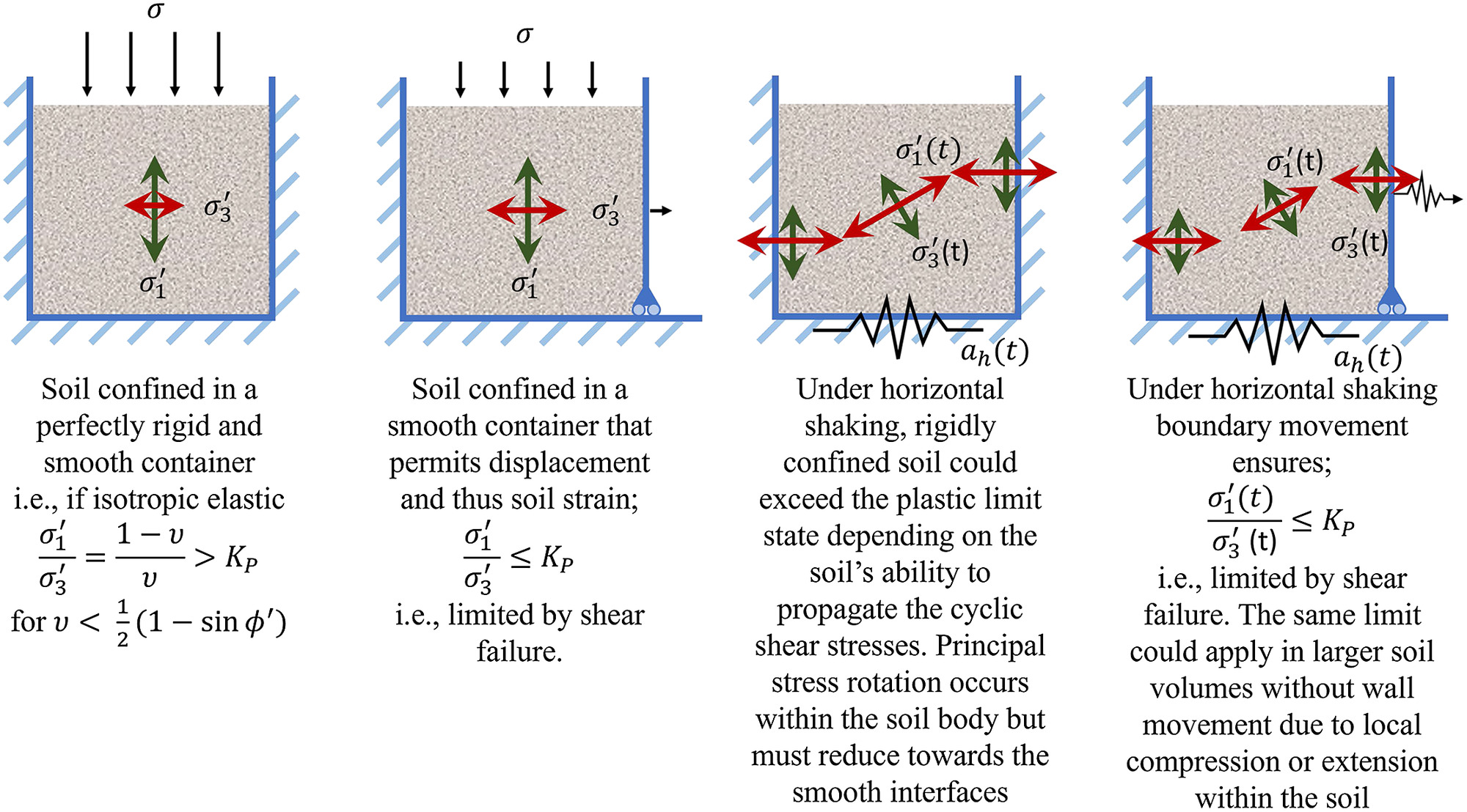
The behavior for the rigidly confined case experiencing dynamic loading is less obvious. Analogous to the static case, elastodynamic elastic pulses would not be bounded by though additional considerations include rotation of the principal stresses due to the cyclic shear stresses. Within the soil body, complementary shear stresses allow this rotation, which means the lateral earth pressure coefficient and principal effective stress ratios can diverge. However, in regions approaching smooth walls the lack of complementary shear stress could lead to the principal effective stress ratio and lateral earth pressure coefficients becoming identical. Further, following Eq. (2), this will be approximately true even for moderately rough walls that provide limited complementary shear stresses. The ability of the soil volume to transmit shear stresses that exceed the material’s frictional (plastic) strength should also be considered. This could be possible in a small, perfectly confined soil volume that behaves elastically but seems less likely in a large soil volume. In this case, nonuniform horizontal strains could develop across the soil body, i.e., larger compression or extension of soil near the walls versus the middle leading to plastic passive or active limit states locally. More straightforwardly, when the wall displacement permits sufficient soil strain (i.e., the last case in Fig. 3) the limiting stress state at the smooth wall-soil interface will match the static case.
At the heart of these considerations is whether a macroscopic frictional model to limit soil’s shear strength is valid at all strains (and perhaps also over what volume of soil it can be applied). If it is not valid, elastoplastic constitutive laws that enforce the Mohr-Coulomb limit at all strains may not be appropriate. If it is, large elastic pulses unbounded by friction predicted by analytical and numerical methods are potentially misleading. Finally, Fig. 3 highlights that under the horizontal shaking, , both and could vary with time. The current study investigates and hypothesizes that
•
Under purely horizontal acceleration, retained soil can exhibit dynamic vertical effective stresses due to rocking mechanisms that are a function of the wall-soil interface properties and system dynamics.
•
Dynamic vertical effective stresses can explain past observations of dynamic horizontal effective stresses not being bounded by the plastic limit state that may have motivated different dynamic earth pressure coefficients as a function of wall displacement.
•
Eq. (1) is appropriate to predict the limiting stress state for soil characterized by a macroscopic friction angle irrespective of static and dynamic loading or wall displacement. In the case of smooth soil-wall interfaces, dynamic earth pressure coefficients should be directly replaced with Eq. (1) (or its reciprocal) and an estimate of the dynamic vertical effective stress to accurately predict the limiting dynamic horizontal effective stresses.
•
Dynamic earth pressure coefficients that incorrectly assume geostatic vertical stresses will predict inaccurate limiting stress states and thus forces experienced by the earth-retaining system. These could be conservative or unconservative depending on the rocking mechanics neglected.
Rocking of Retained Soil: Evidence and Interpretation
Centrifuge testing and corresponding finite element analyses were conducted to test the rocking induced by horizontal shaking in a level retained soil body adjacent to a smooth wall [full details reported by Westcott (2023)]. Fig. 4 shows the centrifuge model cross section, the corresponding numerical mesh and boundary conditions. A centrifugal acceleration of 60 g at a third of the deposit height was applied. A level bed of dry, F-65 Ottawa sand was poured using an automatic spot pluviator targeting a relative density of 40% across the soil profile. This density was chosen to balance limiting the range of friction angles the soil could mobilize and avoiding excessive densification between shakes. At the prototype scale, the centrifuge model boundaries can be interpreted as two, tall walls that are fully fixed at their base and retaining soil wide, i.e., a greater separation than adjacent passive and active wedges. The vertical boundaries are faced with acetate to approach a smooth wall interface in the experiments, though it should be acknowledged that practically some wall friction and thus complementary shear stresses are inevitable. The acetate covers absorbing duct seal inserts, typically used to reduce wave reflection and dissipate energy in dynamic centrifuge tests [e.g., Cui et al. (2022)]. Their use in the present study helps reduce the interaction between the two walls. However, this also means that the wall-soil interfaces are not fully rigid.
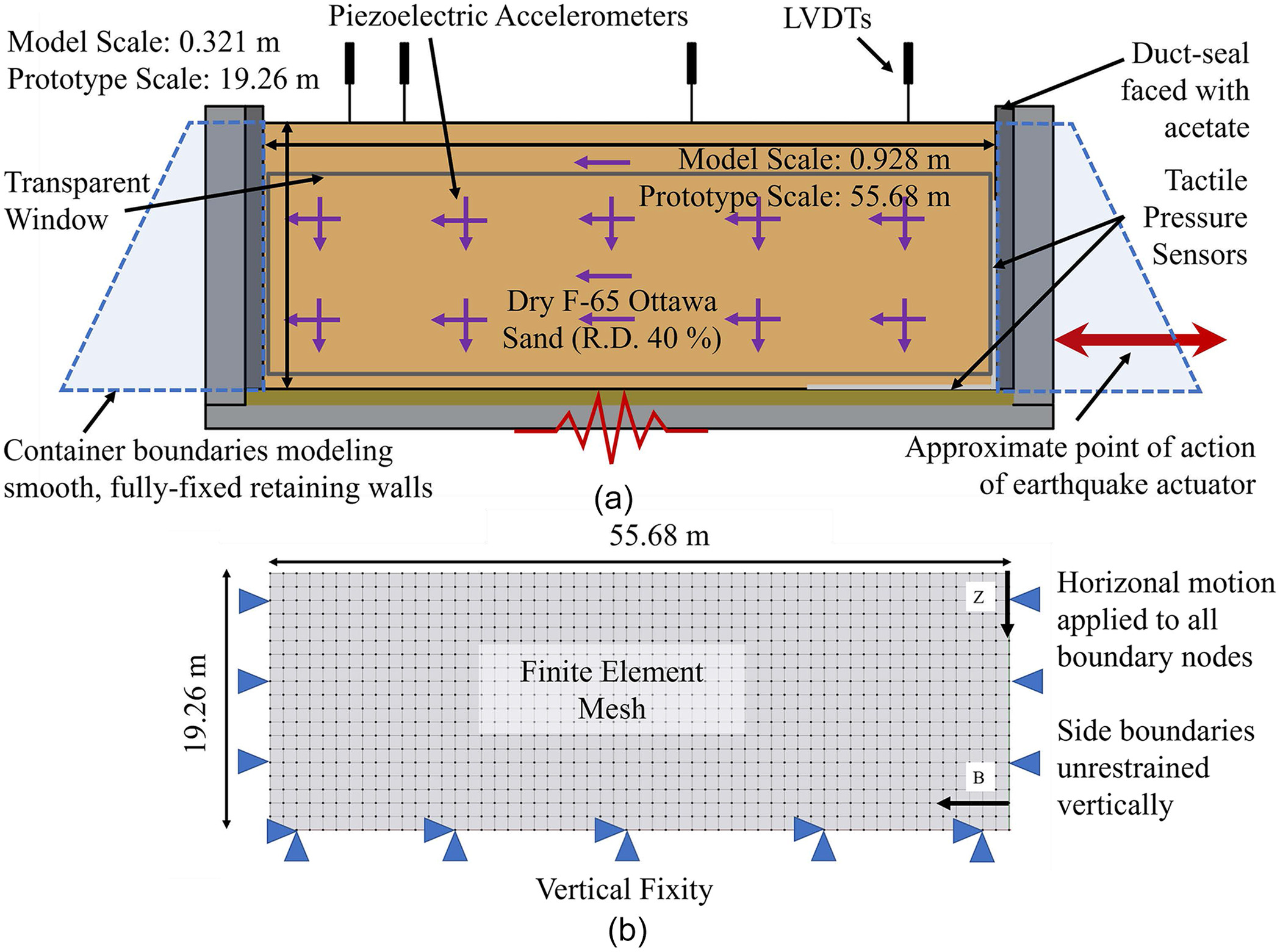
Fig. 4 also shows the instrumentation layout focusing on the sensor results reported in this study. Horizontal and vertical accelerometer pairs were used to provide better coupling with the soil (versus the triaxial sensors used externally) during the applied motion. Displacement transducers were used to track the soil height, and thus density, between shakes. Though not discussed in the present study, a high speed (1,110 frames per second) camera focused on the right hand side of the soil deposit was used to obtain the dynamic displacement fields via digital image correlation (White et al. 2003). Tactile pressure sensors sampling at 730 Hz were also used to evidence dynamic normal vertical and horizontal stresses at the right corner of the deposit.
The numerical boundary conditions idealize the experiments. The base nodes were fixed vertically. The vertical boundaries were fixed horizontally and unrestrained vertically, i.e., modeling a perfectly rigid, smooth wall-soil interface. Purely horizontal shaking is applied to the base and side boundary nodes, based on the measured input for the centrifuge tests but excluding any parasitic, out of plane components to elucidate the rocking mechanics. Sadeghi et al. (2024) trialed more complex lateral boundary conditions featuring spring-dashpot combinations in parallel to capture the finite stiffness and damping of the duct seal. Ultimately, they concluded similar results to the centrifuge data could be obtained with the simplified boundary conditions shown in Fig. 4 and that the selection of soil constitutive parameters was more influential.
The Manzari-Dafalias constitutive model was used in this study (Manzari and Dafalias 2004), with the soil constitutive parameters initially calibrated against monotonic consolidated drained tests at different confining pressures and modified based on the cyclic shear stress-strain loops obtained from the centrifuge data (Westcott 2023), i.e., a class C prediction. The final constitutive model parameters and analysis parameters selected are given in Table 2 and the maximum element size was defined following Lysmer and Kuhlemeyer (1969).
| Constitutive model or analysis parameter | Value |
|---|---|
| Shear modulus, | 125 |
| Poisson’s ratio, | 0.3 |
| Initial void ratio, | 0.6 |
| Critical state stress ratio, | 0.967 |
| Ratio of critical state stress ratio in extension and compression, c | 0.67 |
| Critical state line constant, | 0.02 |
| Critical void ratio at , e0 | 0.78 |
| Critical state line constant, | 1.15 |
| Yield surface constant, m | 0.015 |
| Constant parameter, | 7.05 |
| Constant parameter, | 0.968 |
| Bounding surface parameter, | 3 |
| Dilatancy parameter, | 0 |
| Dilatancy surface parameter, | 0 |
| Fabric-dilatancy tensor parameter, | 4 |
| Fabric-dilatancy tensor parameter, | 600 |
| Rayleigh damping, | 1.48 |
| Rayleigh damping, | 0.00125 |
| Implicit Newmark time integration, | 0.25 |
| Implicit Newmark time integration, | 0.5 |
For brevity, only the results from the third applied motion are discussed. The measurements were low-pass filtered at 400 Hz (model scale) unless stated otherwise and results are presented at the prototype scale. All three motions were ramped, 1 Hz sinusoids with approximately 10 cycles at the full amplitude. The first motion was an , nondestructive shake intended to remove any potential soil arching (Madabhushi and Haigh 2019). The results from the larger (0.3 g) third motion are focused on rather than the second, shake as more of the soil profile reached the limit state in the stronger shake. Based on the LVDT measurements, the density after two shakes was estimated to have increased from to . As the walls are fixed with respect to the base, the soil is driven toward limit states due to relative compression or extension of the retained soil as it moves toward or away from the walls.
A comparison of the measured and predicted accelerations within the retained soil is shown in Fig. 5. A schematic representation of the model cross section is included in the figures to indicate the instrument position. Figs. 5(a and b) illustrate that the amplification and phase lag of the vertically propagating shear waves was broadly captured by the numerical model. The cyclic shear stress-strain curves, inferred from the acceleration data band-pass filtered between 30 and 400 Hz (model scale), help justify the parameters chosen for the soil constitutive model. Based on Fig. 5(b), the shear wave velocity predicted is approximately in a typical cycle. However, it should be noted that the cyclic shear stress-strain curves characterize the response of the central soil column in the rigid container-soil system experimentally and numerically modeled and that this may deviate from the free-field soil response. Fig. 5(c) shows that the applied base shaking results in measurable, out-of-phase (though not perfectly anti-symmetric) vertical accelerations across the soil body. The inner pair of accelerometers show the same trends but with smaller magnitudes, i.e., also supporting rocking of the soil body [Fig. 5(d)]. Vertical accelerations induced by the Coriolis effect were predicted to have a small peak magnitude of 0.017 g due to the large radius of the centrifuge and in any case would be in phase. Westcott (2023) discusses how the parasitic vertical accelerations measured at the centrifuge model base could either be from the shake table actuator (despite the intentionally designed high point of action of the actuator) and/or induced in the table by the rocking centrifuge model. Nevertheless, the idealized numerical model shows that with zero vertical acceleration input, out-of-phase vertical accelerations are still predicted. Fig. 5(e) confirms that the largest vertical acceleration components are at the horizontal driving frequency.
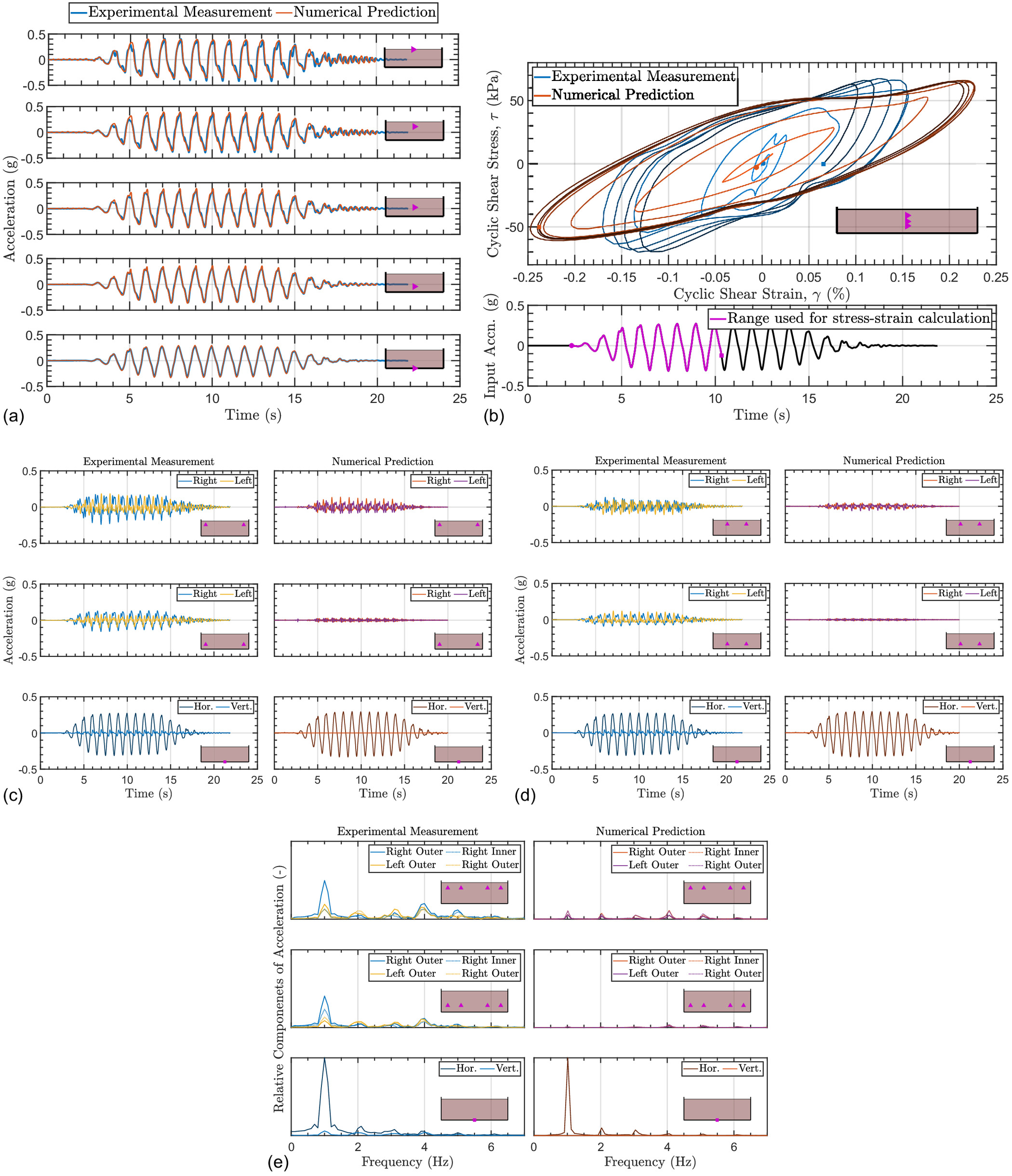
Overall, Fig. 5 clearly shows rocking of the soil body and provides support that the numerical predictions broadly capture the observed mechanical response of the retained soil. This study focuses on the implication of this rocking behavior for the seismic design of earth-retaining structures, rather than validation and refinement of the numerical predictions. Westcott (2023) previously provided comparisons of the experimental and numerical predictions, including the distribution and time histories of the dynamic displacements using PIV and horizontal and vertical stresses from the tactile pressure-sensing sheets. While acknowledging that the complex dynamic soil response from the centrifuge experiments was not fully captured by the idealized numerical model, the internally consistent numerical predictions of the soil stress state and displacements can be used to progress an understanding of the retained soil behavior.
For example, the rocking induced by the horizontal shaking is demonstrated by the predicted relative displacements shown over half a representative cycle in Fig. 6(a). The vertical displacements were confirmed to oscillate at the driving frequency of the applied motion. Due to the displacement of both the base and side walls, soil wedges are not expected. Nevertheless, examining the absolute and relative stress fields instantaneously mobilized in Figs. 6(b–d) shows that the soil rocking induces large changes of dynamic horizontal effective stress due to the relative compressions and extension of the soil with respect to the walls. Further, the dynamic vertical effective stress changes, particularly near the wall base, are significant. A reversal of the regions under- and over-stressed shown in Fig. 6(d) was confirmed to occur in the opposite half cycles.
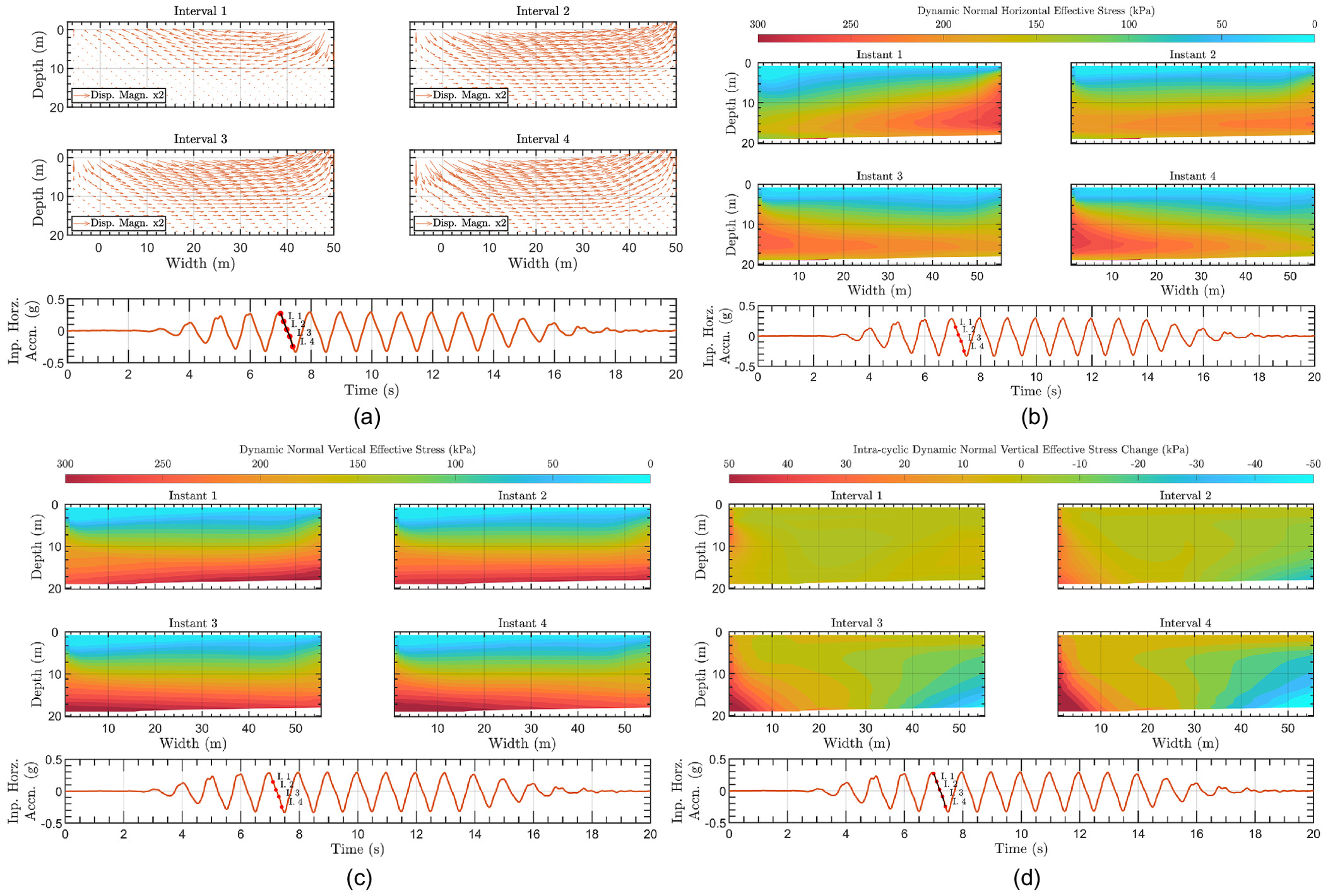
It is clear that significant dynamic vertical effective stresses will change the bounds of dynamic horizontal soil stresses that can be mobilized. As these can be induced by purely horizontal shaking adjacent to a soil-structure interface with reduced interface friction, this phenomena is relevant for the dynamic horizontal forces that a broad range of soil-retaining systems will experience.
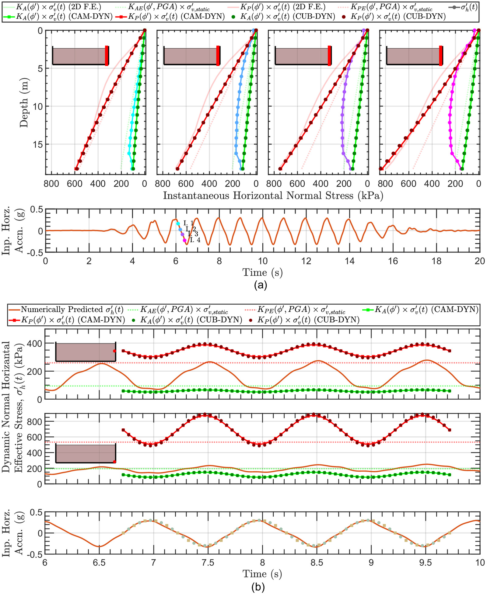
Previous studies have neglected the possible generation of these dynamic vertical effective stresses and thus potentially misinterpreted the limiting dynamic stress states. Fig. 7(a) shows the relative magnitude and direction of the principal effective stresses over half a cycle of horizontal shaking. Due to the cyclic shear stresses, principal effective stress rotation occurs within the soil body but becomes negligible as the smooth walls are approached. Thus, the lateral earth pressure coefficient and limiting principal effective stress ratio are equivalent in these regions. With this in mind, Fig. 7(b) illustrates time histories of the mobilized stress ratios at the soil-smooth wall boundary. It is evident that the calculated mobilized principal stress ratio is quite different depending on the treatment of the vertical effective stresses. In the first case, geostatic stresses are assumed which is the basis for many dynamic earth pressure coefficient interpretations. The conventional interpretation is potentially confusing as the earth pressure coefficient, equivalent to the limiting stress ratio in this region even during shaking, is not bounded by any limit state. In the second case, results from the proposed interpretation utilizing the dynamic vertical effective stresses are shown. The M-O approach is illustratively chosen in Fig. 7(b), calculated using a purely horizontal PGA of 0.3 g, and zero wall friction, wall inclination, and back-fill inclination, respectively. The specific comparison shows both the dynamic active and dynamic passive limit state being crossed. However, this typifies an issue of any approach defining a different limiting soil stress state for dynamic versus static conditions. On the other hand, the proposed interpretation confirms that it is the static earth pressure coefficients, rather than dynamic earth pressure coefficients, that bound the soil stress state at all times. To allow the values to cycle above and below 1, the ratio of the closest principal stress to the horizontal () and vertical () is used.
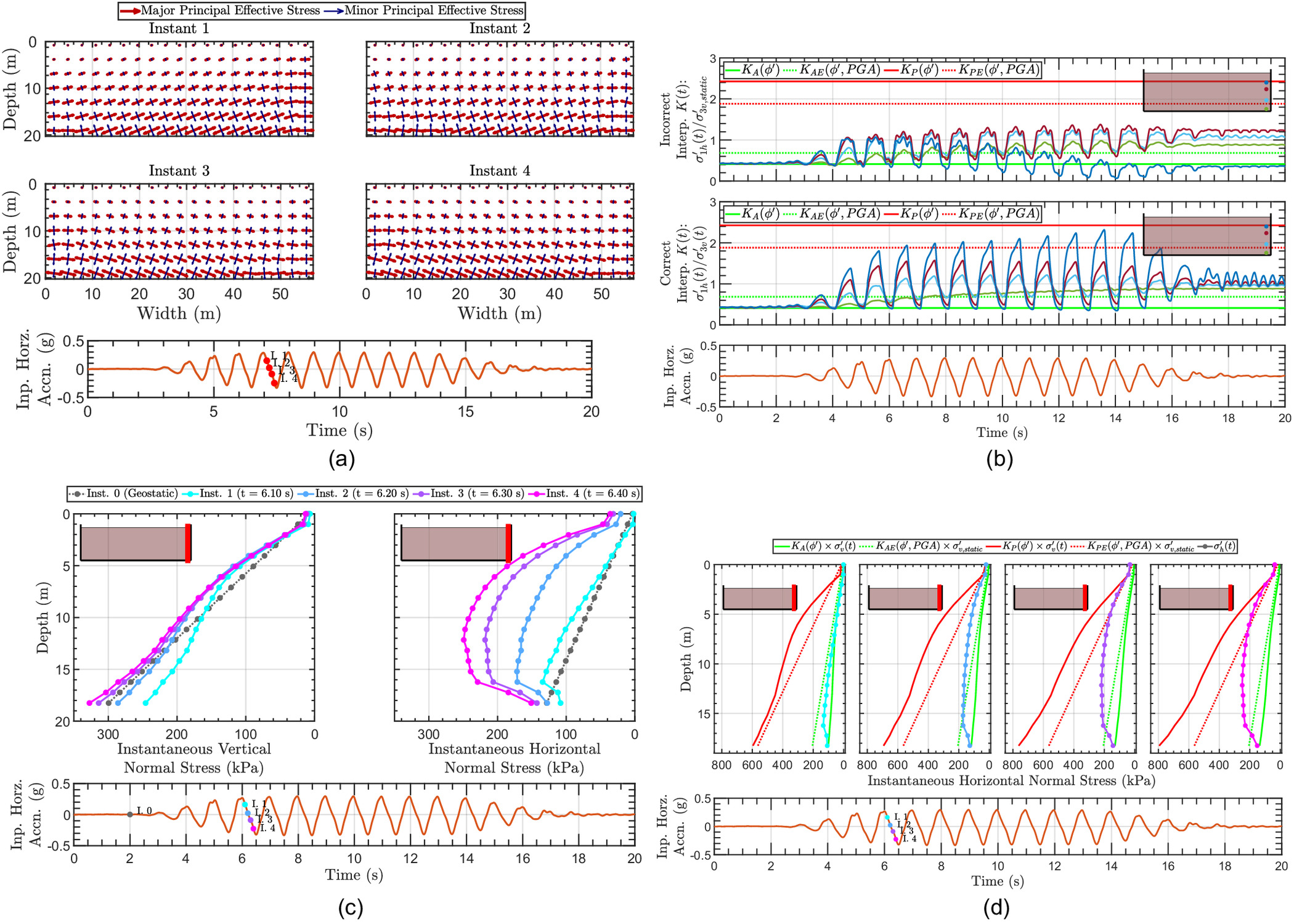
Figs. 7(c and d) additionally explore the instantaneous distributions of normal vertical and horizontal effective stresses at the right boundary wall. The significant cyclic deviation of the vertical effective stress about the geostatic value must be recognized in order to bound the horizontal normal stresses using static earth pressure coefficients. Again, both the active and passive dynamic earth pressure coefficients that conventionally utilize geostatic stresses are violated.
Finally, it is recognized that the behavior observed numerically is necessitated by all Mohr-Coulomb-based constitutive models. Nevertheless, the validation of the acceleration predictions, displacement, and stress trends [Westcott (2023)] against the centrifuge data suggests larger elastic pulses were not missed in this case. It is further noted that the experimental design featured walls fixed with respect to the base, i.e., elastic pulses were not prevented due to rotation/displacement at the wall toes.
Paths Forward for the Seismic Design of Soil-Retaining Systems
The previous results can motivate a move away from dynamic earth pressure coefficients (be they pseudostatic, pseudodynamic, or elastic) in favor of methods that combine static earth pressure coefficients with predictions of the mobilized and limiting dynamic vertical effective stresses adjacent to a soil-retaining system. Such an approach is more fundamentally related to the definition of soil’s macroscopic shear strength. Practically, it can also prevent the under- or over-prediction of limiting seismic stresses as shown in the previous section.
Predicting Dynamic Normal Vertical Stresses
To demonstrate paths forward for seismic design for soil-retaining systems, simplified analytical predictions of the dynamic normal vertical effective stresses are first explored. Rocking of a soil body due to a lack of complementary shear stresses at the boundaries (i.e., two smooth soil-wall interfaces) is considered (Madabhushi 2018; Madabhushi and Haigh 2021b; Westcott 2023). This approach cannot directly be applied for rough retaining walls where significant stress rotation is expected at the soil-wall interface.
Fig. 8(a) proposes two, simplified analytical schemes that could be adopted for a soil mass of width and height retained between two smooth walls and experiencing a purely horizontal acceleration varying with time . Referred to as the CAM-DYN analytical method, a linear redistribution of normal vertical stresses that maintains vertical equilibrium and equilibrates the inertial overturning moment can be derived. This is analogous to methods used for eccentrically loaded earth-retaining systems. Eq. (3) presents the final solution, expressed as the ratio that is the maximum amount of under- or over-stressing relative to the geostatic stress () for the horizontal slice
(3a)
(3b)
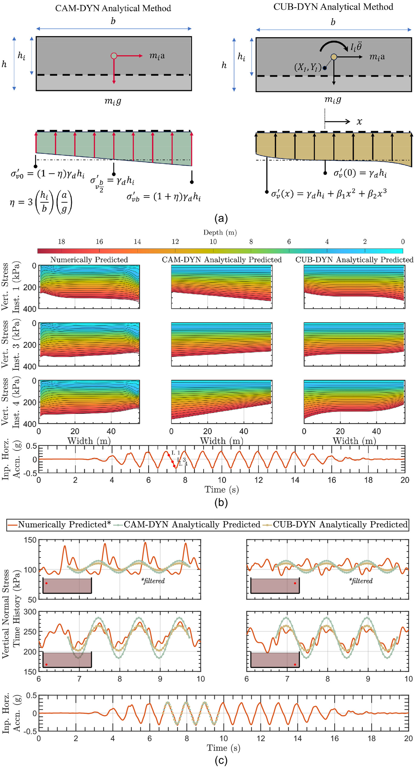
Eq. (3) estimates an instantaneous distribution of dynamic vertical normal stress as a function of the soil block geometry ratio and normalized input acceleration. Key assumptions in this approach include independent rigid soil slices with no net vertical acceleration, infinitesimally small rotations, negligible rotational inertia, linearly redistributed stresses across the entire soil width, and rotation about the center of the block’s base.
The extended CUB-DYN methodology, also shown in Fig. 8(a), assumes a nonlinear stress distribution [of the form in Eq. (4a) based on the previous observations], and accounts for the linear and rotational inertia about an arbitrary point of rotation. By solving for moment and geostatic vertical equilibrium, a closed form solution can be derived [Eq. (4)]. For a given center of rotation and instantaneous acceleration (that also defines the rotational acceleration by their kinematic relation), the coefficients and are solved to define the (dynamic D’Alembert) equilibrating stresses. While inelegant due to the form of the assumed stress distribution, the results are tractable and analytical stress predictions were readily made by using a symbolic system of equations solver. This approach would support any other equilibrating stress distributions assumed
(4a)
(4b)
(4c)
(4d)
(4e)
(4f)
(4g)
Fig. 8 compares the previous numerically obtained stress predictions and proposed analytical solutions. Fig. 8(b) shows the magnitudes of three instantaneous normal vertical stress predictions with depth across horizontal slices. The acceleration time history indicates the acceleration used as an input for each instant, with the CUB-DYN method additionally specifying a center of rotation at half of each slice height and 45% the width, the latter choice being inspired by Fig. 6(a). The ability of these analytical methods to broadly capture the distribution of cyclic rocking stresses is demonstrated. Fig. 8(c) shows how inputting an acceleration time history can also produce reasonable predictions of the time-varying vertical stresses versus the finite element solutions. Four locations are shown, and the comparison close to the left and right soil boundaries at two heights shows that the oscillations at the driving frequency, antiphase relation between opposite sides, and diminishing magnitude with height are all captured by the simple analytical methodologies based only on inertial considerations. It is noted that the numerically predicted time histories at the upper gauss points were filtered to remove a physically unreasonable stress drift. This was observed at low confining pressures by multiple constitutive models used in OpenSEES (Westcott 2023). Between the CAM-DYN and CUB-DYN methods, there is a trade-off between accuracy and inputs required, but either approach is far quicker and simpler than a dynamic 2D finite element analysis. Given the assumption of rigid soil blocks, the phase lag with height cannot be captured. However, the methodology is amenable to extensions accounting for wave propagations through soils with finite stiffness in a similar way to the pseudodynamic extension of pseudostatic methods (Steedman and Zeng 1990).
An application of the proposed analytical approaches is shown in Fig. 9. Following Fig. 7(d), Fig. 9(a) focuses on the distributions of numerically predicted horizontal stresses at four instants during the shaking that were shown to violate limit states defined by the dynamic earth pressure coefficients. However, these stresses were limited by the product of the Rankine coefficients and time-varying vertical stresses numerically predicted. Fig. 9(a) shows that the distribution of vertical stresses adjacent to the sidewall using the CAM-DYN and CUB-DYN analytical predictions can also be combined with the Rankine coefficients to reasonably bound the stresses at a given instant. This is despite the simplified rocking mechanisms not capturing the full complexity of the instantaneous distributions of vertical stresses with height [e.g., the turning point at seen in Fig. 7(c)]. Fig. 9(b) confirms this; the horizontal effective stress time histories at two heights are not limited by conventional approaches while the similar vertical effective stress time history predictions by the CAM-DYN and CUB-DYN approach combined with the Rankine coefficients are bounding. While conventional approaches have utilized a PGA to define a potentially incorrect and constant limit state, the proposed approach could use either the PGA or acceleration time history as shown to better capture the variation of limiting stresses and thus lead to more accurate factor of safety estimates.
The proposed approach illustrates a path forward for improved seismic limit state design of earth-retaining structures. The CUB-DYN method could be readily extended to incorporate phase lag of the accelerations if the representative soil stiffness can be estimated. However, some limitations of the current study should be noted. Firstly, further study is required to adapt this approach for rough soil-wall interfaces where the principal effective stresses are substantially rotated away from the horizontal and vertical directions. Additionally, the simplified inertial method can only predict stress time histories with the same frequency content as the acceleration time history. The 1 Hz driving frequency was chosen to avoid exciting the anticipated natural shear modes of the retained soil, i.e., to avoid resonance. More complex instantaneous distributions and time histories for the vertical effective stress could arise depending on dynamic soil-structure interaction effects on the rocking mechanism. The extent of this interaction between the input motion and dynamic characteristics of the retained soil-wall system (that also vary with soil strains) requires further consideration, particularly when additional degrees of freedom for the wall system are introduced. Finally, the proposed rocking mechanisms span the soil body retained between the two smooth walls and thus predict increases and decreases of the normal vertical effective stresses across the entire horizontal plane of retained soil. In the case of a very long back-fill (between two smooth walls or behind a single wall) a transition may be expected between the rocking region and the nonrocking free-field. Suffice to say in these cases that the lateral extent of the rocking region needs to be established and the linear redistribution of the CAM-DYN approach may imply too abrupt a transition between these zones. While a nonlinear vertical stress function potentially allows a smoother transition between the rocking and vertically geostatic zones, the first step is to better understand the altered rocking mechanisms which are revisited in the “Discussion” section.
Repurposing Dynamic Earth Pressure Coefficients
The proposed approach uses Rankine earth pressure coefficients combined with estimates of the dynamic normal vertical effective stress to define the limiting dynamic horizontal stresses. These vertical stress oscillations necessitate local vertical accelerations, i.e., the tendency for rotation and thus stress redistribution across an individual, rotating horizontal slice is caused by opposite regions of soil accelerating upwards and downwards.
Thus, an alternative approach would be to predict a single representative or distribution of vertical accelerations along a soil-wall interface from the rocking mechanism induced by the purely horizontal shaking. These vertical accelerations could be used with pseudostatic or pseudodynamic dynamic earth pressure coefficients (i.e., calculated using both a and for a purely horizontal input) and multiplied with the geostatic vertical stresses to obtain estimates of the limiting dynamic horizontal stresses. The becomes a proxy for the normal vertical stress change and would allow designers to continue using dynamic earth pressure coefficients. In fact, the CAM-DYN or CUB-DYN vertical stress predictions could be divided by the mass per area to directly obtain the implied distribution of vertical accelerations, which would ultimately yield identical results to Fig. 9.
However, such repurposing could continue to obscure the importance of dynamic normal vertical stresses that have been historically missed. Further, the established nomenclature can confuse ratios that are actually limiting dynamic force coefficients rather than limiting dynamic stress/earth pressure ratios.
Discussion
Overall, this work highlights the occurrence of dynamic normal vertical effective stresses generated by purely horizontal shaking that have previously been largely neglected. The rocking of a level, dry soil body retained between two smooth walls experiencing horizontal shaking was confirmed by dynamic centrifuge testing and mechanically validated numerical analyses. The rocking manifests as vertical accelerations and hence dynamic vertical stresses. These are significant because they alter the limiting horizontal stresses, and thus forces, the retaining system can experience.
Such oscillations are likely relevant for a broad variety of soil-retaining systems, as illustrated by Fig. 10. The soil could be retained by gravity retaining walls as shown, but equally could be sheet pile walls or the side walls of a buried reservoir or basement. While rocking can occur due to a lack of complementary shear (i.e., at smooth soil-wall interfaces), it can also be induced by a moving rough soil-wall interface (Madabhushi and Haigh 2021b). In the specific case of a level soil bed retained between fully rough walls that are fixed with respect to the soil’s vertical displacement, no rocking would be expected and the geostatic vertical stresses and shear stresses combined with the Rankine coefficients will bound the horizontal seismic pressures. Fig. 10 shows how the rocking mechanisms and dynamic normal vertical effective stresses can be broadly attributed to a transition of boundary conditions between the free-field and retained soil. Ultimately, the ability of shear stresses to be borne on the horizontal and vertical planes in the soil will control the extent of these dynamic oscillations. Predicting the magnitude, phasing, and horizontal extent of soil away from the wall experiencing the dynamic normal vertical effective stresses induced by these different geometric cases and soil-wall interface conditions is the topic of future studies.
Notwithstanding this, careful examination of the measured and predicted dynamic states by the present study provides a simple interpretation of limiting dynamic stress states that can help resolve the longstanding uncertainty of the validity of dynamic earth pressure coefficients. While pseudostatic coefficients were originally derived as an estimate of the dynamic limiting force ratio for a soil at its plastic limit state, past studies and the current work show that they do not truly define the limiting active or passive horizontal stresses experienced during horizontal shaking. Past work has attributed this to limitations of the methodology in terms of relative soil-wall displacements or the amplification and phasing of the vertically propagating accelerations.
The present work argues that for many practical boundary conditions retained soil experiencing shear stresses from vertically propagating horizontal accelerations will be limited by the shear strength of the soil at its plastic limit state. With this in mind, past studies that found horizontal stresses not limited by the product of the dynamic earth pressure coefficient and geostatic stress could be due to dynamic vertical stresses that were missed. In these cases, combining the Rankine earth pressure coefficient with the dynamic vertical stresses will define the limiting dynamic stresses, rather than necessarily motivating earth pressure coefficients that ignore the soil’s limiting shear strength (e.g., purely elastic approaches).
There have been many attempts to develop dynamic earth pressure coefficients that are different to the ‘static’ Rankine coefficients. Some of these approaches could be repurposed to account for vertical accelerations induced by horizontal shaking, and thus implicitly account for dynamic vertical stresses. However, a more direct approach would be to estimate the time-varying or maximum deviation of the vertical effective stresses due to seismic accelerations. The CAM-DYN and CUB-DYN approaches described demonstrate how straightforward inertial calculations could be used to broadly capture the dynamic vertical effective stresses. The combination of these simple predictions with the Rankine earth pressure coefficients agreed well with the more involved finite element predictions in the present study, illustrating a path forward for seismic limit state design that replaces dynamic earth pressure coefficients and does not necessitate numerical approaches. However, the scope to adapt these methods for rough retaining walls, to capture the dynamic soil-structure interaction of the rocking mechanism versus the input motion characteristics, and to predict the transition between rocking and free-field regions requires further research. As shown in Fig. 10, the rocking dynamics will depend both on the dynamic characteristics of the soil and wall as more complex earth-retaining systems are considered. Overall, the current work has first focused on properly defining the dynamic limiting stress state that is altered by rocking mechanisms and can be superposed with the retained soil’s translational mechanisms. Predicting the dynamically mobilized stresses (both vertically and horizontally), e.g., for performance based design, also requires further study. Nevertheless, the principal stress ratios would remain between and throughout the dynamic loading.
Finally, it is recognized that the experiments featured absorbing duct seal boundaries that, despite their primary absorption mechanism being viscous damping, were not perfectly rigid. Further, constitutive models based on the Mohr-Coulomb failure criterion will not allow principal stress ratios to exceed the Rankine coefficient. A remaining question is whether a hypothetical geometry where soil is more rigidly confined and is subject to very large accelerations could yield principal stress ratios that exceed the Rankine values. Important factors to consider, and identify whether such a situation is practically relevant, would be the soil volume (larger soil volumes could compress away from a rigid boundary) and the need for a different, stronger medium to transmit the large accelerations to the retained soil. To the best of the authors’ knowledge, experimental evidence for such a scenario where the possibility of dynamic vertical effective stresses were explicitly eliminated does not exist.
Conclusions
The current work demonstrates that for a material that can be characterized by a macroscopic friction angle the Rankine coefficients define both the static and dynamic limiting stress state of the soil. This required the discovery of dynamic normal vertical effective stresses induced by horizontal shaking. This conclusion is independent of relative soil-wall displacements (e.g., yielding versus non yielding cases) and thus addresses a longstanding gap between plastic and elastic approaches to defining the limiting dynamic stress state in retained soil. Ultimately, approaches that seek to define dynamic earth pressure coefficients distinct from the static earth pressure coefficients may be unnecessary. Instead, the presence of any dynamic normal vertical effective stresses could be captured, e.g., following the inertial methods presented, and combined with the Rankine coefficients to yield improved seismic limit state design of earth-retaining structures.
Data Availability Statement
Some or all data, models, or code that support the findings of this study are available from the corresponding author upon reasonable request.
Acknowledgments
The authors are grateful for the technical and moral support from the staff and researchers who enabled the centrifuge testing conducted at the Center for Infrastructure, Energy and Space Testing and the Boulder Geomechanics and Geohazards Research Group at the University of Colorado Boulder. The support from the DoD’s Science, Mathematics And Research for Transformation (SMART) Scholarship and CU Boulder’s Engineering Excellence Fund is also gratefully acknowledged. Finally, the authors sincerely appreciate the thought-provoking comments received from the anonymous reviewers.
References
Al Atik, L., and N. Sitar. 2010. “Seismic earth pressures on cantilever retaining structures.” J. Geotech. Geoenviron. Eng. 136 (10): 1324–1333. https://doi.org/10.1061/(ASCE)GT.1943-5606.0000351.
Al-Atik, L., and N. Sitar. 2009. “Seismically induced lateral earth pressures: A new approach.” In Proc., 17th Int. Conf. on Soil Mechanics and Geotechnical Engineering: The Academia and Practice of Geotechnical Engineering, 1417–1420. Amsterdam, Netherlands: IOS Press.
Al-Homoud, A. S., and R. V. Whitman. 1995. “Comparison between FE prediction and results from dynamic centrifuge tests on tilting gravity walls.” Soil Dyn. Earthquake Eng. 14 (4): 259–268. https://doi.org/10.1016/0267-7261(94)00051-H.
Athanasopoulos, Z. A., K. Lamote, and G. A. Athanasopoulos. 2012. “Use of EPS geofoam compressible inclusions for reducing the earthquake effects on yielding earth retaining structures.” Soil Dyn. Earthquake Eng. 41 (Oct): 59–71. https://doi.org/10.1016/j.soildyn.2012.05.004.
Athanasopoulos, Z. A., V. S. Vlachakis, and G. A. Athanasopoulos. 2013. “Phasing issues in the seismic response of yielding, gravity-type earth retaining walls—Overview and results from a FEM study.” Soil Dyn. Earthquake Eng. 55 (Dec): 59–70. https://doi.org/10.1016/j.soildyn.2013.08.004.
Bolton, M. D., and R. S. Steedman. 1982. “Centrifugal testing of micro concrete retaining walls subject to base shaking.” In Proc., Conf. on Soil Dynamics and Earthquake Engineering. Southampton, UK: A.A. Balkema.
Brandenberg, S. J., G. Mylonakis, and J. P. Stewart. 2015. “Kinematic framework for evaluating seismic earth pressures on retaining walls.” J. Geotech. Geoenviron. Eng. 141 (7): 04015031. https://doi.org/10.1061/(ASCE)GT.1943-5606.0001312.
Breslau-Müller, H. 1906. Erddruck auf Stützmauern. Stuttgart, Germany: Alfred Kroener.
Chen, W. F., and X. L. Liu. 1990. Limit analysis in soil mechanics. New York: Elsevier.
Collins, I. F. 1973. “A note on the interpretation of Coulomb’s analysis of the thrust on a rough retaining wall in terms of the limit theorems of plasticity theory.” Géotechnique 23 (3): 442–447. https://doi.org/10.1680/geot.1973.23.3.442.
Coulomb, C. A. 1776. “An attempt to apply the rules of maxima and minima to several problems of stability related to architecture.” Mémoires de l’Académie R. Sci. 7 (Jun): 343–382.
Cui, G., C. Heron, and A. Marshall. 2022. “Effect of Duxseal on horizontal stress and soil stiffness in small-amplitude dynamic centrifuge models.” Geotech. Test. J. 45 (3): 571–589. https://doi.org/10.1520/GTJ20200308.
Dakoulas, P., and G. Gazetas. 2008. “Insight into seismic earth and water pressures against caisson quay walls.” Geotechnique 58 (2): 95–111. https://doi.org/10.1680/geot.2008.58.2.95.
Deng, Y., Z. Yan, N. He, J. Chang, and Y. Xuan. 2022. “Study on seismic amplification effect and active earth pressure of retaining wall based on pseudo-dynamic method and numerical simulation.” J. Geol. Soc. India 98 (3): 431–439. https://doi.org/10.1007/s12594-022-1996-z.
Dewoolkar, M. M., H.-Y. Ko, and R. Y. S. Pak. 2001. “Seismic behavior of cantilever retaining walls with liquefiable backfills.” J. Geotech. Geoenviron. Eng. 127 (5): 424–435. https://doi.org/10.1061/(ASCE)1090-0241(2001)127:5(424).
Dewoolkar, M. M., A. T. Stadler, S. N. Batiste, and H. Y. Ko. 1995. “Dynamic centrifuge experiment on a cantilever retaining wall.” In Proc., 3rd Int. Conf. on Advances in Geotechnical Earthquake Engineering and Soil Dynamics, 1117–1121. St. Louis: Univ. of Missouri-Rolla.
Drucker, D. C., W. Prager, and H. J. Greenberg. 1952. “Extended limit design theorems for continuous media.” Q. Appl. Math. 9 (4): 381–389. https://doi.org/10.1090/qam/45573.
Elms, D. G., and R. Richards. 1979. “Seismic design of gravity retaining walls.” Bull. N. Z. Nat. Soc. Earthquake Eng. 12 (2): 114–121.
Garcia-Suarez, J., and D. Asimaki. 2020. “Exact seismic response of smooth rigid retaining walls resting on stiff soil.” Int. J. Numer. Anal. Methods Geomech. 44 (13): 1750–1769.
Garcia-Suarez, J., D. Asimaki, and M. Ortiz. 2021. “Applications of the J-integral to dynamical problems in geotechnical engineering.” J. Mech. Phys. Solids 150 (May): 104353. https://doi.org/10.1016/j.jmps.2021.104353.
Gazetas, G., N. Gerolymos, and I. Anastasopoulos. 2005. “Response of three Athens metro underground structures in the 1999 Parnitha earthquake.” Soil Dyn. Earthquake Eng. 25 (7–10): 617–633. https://doi.org/10.1016/j.soildyn.2004.11.006.
Gazetas, G., P. N. Psarropoulos, I. Anastasopoulos, and N. Gerolymos. 2004. “Seismic behaviour of flexible retaining systems subjected to short-duration moderately strong excitation.” Soil Dyn. Earthquake Eng. 24 (7): 537–550. https://doi.org/10.1016/j.soildyn.2004.02.005.
Geraili Mikola, R., G. Candia, and N. Sitar. 2016. “Seismic earth pressures on retaining structures and basement walls in cohesionless soils.” J. Geotech. Geoenviron. Eng. 142 (10): 04016047. https://doi.org/10.1061/(ASCE)GT.1943-5606.0001507.
Green, R. A., C. Guney Olgun, R. M. Ebeling, and W. I. Cameron. 2003. “Seismically induced lateral earth pressures on a cantilever retaining wall.” Tech. Council Lifeline Earthquake Eng. Monogr. 25 (Jun): 946–955. https://doi.org/10.1061/40687(2003)96.
Hushmand, A., et al. 2014. “Seismic soil-structure interaction and lateral earth pressures on buried reservoir structures.” In Proc., Geo-Congress 2014 Technical Papers, 1215–1224. Reston, VA: ASCE.
Jo, S. B., J. G. Ha, J. S. Lee, and D. S. Kim. 2017. “Evaluation of the seismic earth pressure for inverted T-shape stiff retaining wall in cohesionless soils via dynamic centrifuge.” Soil Dyn. Earthquake Eng. 92 (Jan): 345–357. https://doi.org/10.1016/j.soildyn.2016.10.009.
Khokher, Y. R., and S. P. G. Madabhushi. 2010. “Dynamic earth pressures and earth pressure cell measurements.” In Proc., 7th Int. Conf. on Physical Modelling in Geotechnics 2010, 493–498. Boca Raton, FL: CRC Press.
Khosravi, M. H., T. Pipatpongsa, and J. Takemura. 2016. “Theoretical analysis of earth pressure against rigid retaining walls under translation mode.” Soils Found. 56 (4): 664–675. https://doi.org/10.1016/j.sandf.2016.07.007.
Kloukinas, P., M. Langousis, and G. Mylonakis. 2012. “Simple wave solution for seismic earth pressures on nonyielding walls.” J. Geotech. Geoenviron. Eng. 138 (12): 1514–1519. https://doi.org/10.1061/(ASCE)GT.1943-5606.0000721.
Kramer, S. L. 1996. Geotechnical earthquake engineering. Upper Saddle River, NJ: Prentice Hall.
Lew, M., S. Ebrahim, and M. B. Hudson. 1995. “Performance of shored earth retaining systems during the January 17, 1994, Northridge earthquake.” In Proc., 3rd Int. Conf. on Recent Advances in Geotechnical Earthquake Engineering and Soil Dynamics. St. Louis: Univ. of Missouri-Rolla.
Lew, M., N. Sitar, and L. A. Atik. 2010. “Seismic earth pressures: Fact or fiction? In Vol. 3 of Proc., Earth Retention Conf., 656–673. Reston, VA: ASCE.
Lysmer, J., and R. L. Kuhlemeyer. 1969. “Finite dynamic model for infinite media.” J. Eng. Mech. Div. 95 (4): 859–877. https://doi.org/10.1061/JMCEA3.0001144.
Madabhushi, S. S. C. 2018. “Multi-hazard modelling of dual row retaining walls.” Ph.D. thesis, Dept. of Engineering, Univ. of Cambridge.
Madabhushi, S. S. C., and S. K. Haigh. 2019. “Centrifuge testing of dual row walls in dry sand: The influence of Earthquake sequence and multiple flights.” Soil Dyn. Earthquake Eng. 125 (Oct): 105690. https://doi.org/10.1016/j.soildyn.2019.05.029.
Madabhushi, S. S. C., and S. K. Haigh. 2021a. “Dual row retaining walls in dry sand: Influence of wall stiffness on seismic response.” Can. Geotech. J. 58 (10): 1558–1570. https://doi.org/10.1139/cgj-2020-0538.
Madabhushi, S. S. C., and S. K. Haigh. 2021b. “On the dynamic response of flexible dual-row retaining walls in dry sand.” Géotechnique 72 (11): 1–32. https://doi.org/10.1680/jgeot.19.P.189.
Manzari, M., and Y. Dafalias. 2004. “Simple plasticity sand model accounting for fabric change effects.” J. Eng. Mech. 130 (6): 622–634. https://doi.org/10.1061/(ASCE)0733-9399(2004)130:6(622).
Michalowski, R. L., and N. Park. 2003. “Arching in granular soils.” In Proc., 1st Japan–U.S. Workshop on Testing, Modeling, and Simulation, edited by J. A. Yamamuro and J. Koseki, 255–268. Reston, VA: ASCE Press.
Mikola, R. G., and N. Sitar. 2013. Seismic earth pressures on retaining structures in cohesionless soils By Roozbeh Geraili Mikola and Nicholas Sitar report submitted to the California Department of Transportation (Caltrans) under Contract No. 65A0367 and NSF-NEES-CR Grant No. CMMI-093. Berkeley, CA: Univ. of California.
Mononobe, N., and H. Matsuo. 1929. “On determination of earth pressure during earthquake.” In Proc., World Engineering Congress, Tokyo. Tokyo: Kogakkai.
Mylonakis, G., P. Kloukinas, and C. Papantonopoulos. 2007. “An alternative to the Mononobe-Okabe equations for seismic earth pressures.” Soil Dyn. Earthquake Eng. 27 (10): 957–969. https://doi.org/10.1016/j.soildyn.2007.01.004.
Nadim, F., and R. V. Whitman. 1983. “Seismically induced movement of retaining walls.” J. Geotech. Eng. 109 (7): 915–931. https://doi.org/10.1061/(ASCE)0733-9410(1983)109:7(915).
Nakamura, S. 2006. “Reexamination of Mononobe-Okabe theory of gravity retaining walls using centrifuge model tests.” Soils Found. 46 (2): 135–146. https://doi.org/10.3208/sandf.46.135.
Newmark, N. M. 1965. “Effects of earthquakes on dams and embankments.” Géotechnique 15 (2): 139–160. https://doi.org/10.1680/geot.1965.15.2.139.
Okabe, S. 1924. “General theory on earth pressure and seismic stability of retaining wall and dam.” J. Jpn. Soc. Civ. Eng. 10 (6): 1277–1323.
Ortiz, L. A., R. F. Scott, and J. Lee. 1983. “Dynamic centrifuge testing of a cantilever retaining wall.” Earthquake Eng. Struct. Dyn. 11 (2): 251–268. https://doi.org/10.1002/eqe.4290110207.
Ostadan, F. 2005. “Seismic soil pressure for building walls: An updated approach.” Soil Dyn. Earthquake Eng. 25 (7–10): 785–793. https://doi.org/10.1016/j.soildyn.2004.11.035.
Paik, K. H., and R. Salgado. 2003. “Estimation of active earth pressure against rigid retaining walls considering arching effects.” Géotechnique 53 (7): 643–653. https://doi.org/10.1680/geot.2003.53.7.643.
Psarropoulos, P. N., G. Klonaris, and G. Gazetas. 2005. “Seismic earth pressures on rigid and flexible retaining walls.” Soil Dyn. Earthquake Eng. 25 (7–10): 795–809. https://doi.org/10.1016/j.soildyn.2004.11.020.
Rankine, M. W. J. 1856. “On the stability of loose earth.” Philos. Trans. R. Soc. London 147 (Jun): 9–27.
Sadeghi, K., J. Westcott, and S. S. C. Madabhushi. 2024. “Soil rocking and seismic design implications for retaining walls: Numerical modeling considerations from analyzing a centrifuge test (under review).” Geo-Congress 2024 (1): 1–10. https://doi.org/10.1061/9780784485316.045.
Scott, R. F. 1973. “Earthquake-induced pressures on retaining walls.” In Proc., 5th World Conf. on Earthquake Engineering, 1611–1619. Rome: Editrice Libraria.
Seed, H. B., and R. V. Whitman. 1970. “Design of earth retaining structures for dynamic loads.” In Proc., ASCE Specialty Conf.-Lateral Stress in the Ground and Design of Earth Retaining Structures. Reston, VA: Univ. of California.
Steedman, R. S., and X. Zeng. 1990. “The influence of phase on the calculation of pseudo-static earth pressure on a retaining wall.” Géotechnique 40 (1): 103–112. https://doi.org/10.1680/geot.1990.40.1.103.
Veletsos, A. S., and A. H. Younan. 1994. “Dynamic modeling and response of soil-wall systems.” J. Geotech. Eng. 120 (12): 2155–2179. https://doi.org/10.1061/(ASCE)0733-9410(1994)120:12(2155).
Veletsos, A. S., and A. H. Younan. 1995. “Dynamic soil pressures on rigid vertical walls.” Earthquake Eng. Struct. Dyn. 23 (3): 275–301. https://doi.org/10.1002/eqe.4290230305.
Veletsos, A. S., and A. H. Younan. 1997. “Dynamic response of cantilever retaining walls.” J. Geotech. Geoenviron. Eng. 123 (2): 161–172. https://doi.org/10.1061/(ASCE)1090-0241(1997)123:2(161).
Veletsos, A. S., and A. H. Younan. 2000. “Dynamic response of cantilever retaining walls.” Geotech. Spec. Publ. 60 (12): 19–37. https://doi.org/10.1002/1096-9845(200012)29:12%3C1815::AID-EQE993%3E3.0.CO;2-Z.
Westcott, J. 2023. “An investigation into dynamic normal vertical effective stresses induced by horizontal shaking.” MS thesis, Dept. of Civil, Environmental and Architectural Engineering, Univ. of Colorado Boulder.
White, D. J., W. A. Take, and M. D. Bolton. 2003. “Soil deformation measurement using particle image velocimetry (PIV) and photogrammetry.” Géotechnique 53 (7): 619–631. https://doi.org/10.1680/geot.2003.53.7.619.
Wood, J. H. 1973. “Earthquake-induced soil pressures on structures.” Accessed April 13, 2024. http://caltecheerl.library.caltech.edu/archive/00000211/%5Cnhttp://resolver.caltech.edu/CaltechEERL:1973.EERL-73-05.
Wood, J. H. 1975. “Earthquake-induced pressures on a rigid wall structure.” Bull. N. Z. Soc. Earthquake Eng. 8 (3): 175–186. https://doi.org/10.5459/bnzsee.8.3.175-186.
Youd, T., J. Bardet, and J. D. Bray. 2000. “1999 Kocaeli, Turkey, Earthquake reconnaisance report.” In Earthquake spectra, 237–279. Los Angeles: Sage.
Information & Authors
Information
Published In

Journal of Geotechnical and Geoenvironmental Engineering
Volume 150 • Issue 10 • October 2024
Copyright
This work is made available under the terms of the Creative Commons Attribution 4.0 International license, https://creativecommons.org/licenses/by/4.0/.
History
Received: Aug 22, 2023
Accepted: Apr 8, 2024
Published online: Jul 19, 2024
Published in print: Oct 1, 2024
Discussion open until: Dec 19, 2024
Authors
Metrics & Citations
Metrics
Citations
Download citation
If you have the appropriate software installed, you can download article citation data to the citation manager of your choice. Simply select your manager software from the list below and click Download.