Recycling Large-Format 3D Printed Polymer Composite Formworks Used for Casting Precast Concrete – Technical Feasibility and Challenges
Publication: Journal of Composites for Construction
Volume 28, Issue 6
Abstract
The use of large-format three-dimensional (3D) printed thermoplastic composites as formworks for precast concrete structures has emerged as a cost-effective solution addressing challenges related to skilled labor shortages and enabling design optimization. This research work investigates the technical feasibility of recycling large-format 3D printed polymer composite formworks. Thermomechanical recycling of 3D printed formworks was implemented and the recycled polymer composite feedstock was used to 3D print new formworks. Two commonly used short-fiber reinforced polymer composite materials were evaluated: one petroleum-based material, carbon fiber–filled acrylonitrile butadiene styrene (CF-ABS), and one biobased material, wood flour–filled amorphous polylactic acid (WF-aPLA). Mechanical properties of 3D printed specimens were characterized to evaluate their suitability as 3D printed formworks. Physical and thermal characterization methods were used to understand the change in thermal and mechanical properties of the thermoplastic polymers due to the recycling process. The study also employed similar methods to assess the potential contamination of polymer composites with cementitious materials. Results revealed that high-pressure water washing was effective in removing cementitious material from the formwork surface, and the recycled material did not show significant contamination. Thermomechanical recycling was shown to reduce the fiber length of reinforcing fibers and the molecular weight of the polymer material. The reduction in fiber length and the molecular weight of the material results in the reduction of material viscosity. The observed reductions in viscosity have the potential to limit the number of recycling iterations. However, thermal stability was maintained throughout all processing levels. In addition, the mechanical performance of the WF-aPLA material system was observed to increase after the recycling process. However, the mechanical performance of the CF-ABS material system was observed to decrease after recycling. Recycled 3D printed formworks were found to work effectively, albeit some reduction in mechanical properties of recycled formworks was observed.
Practical Applications
Large-format three-dimensional (3D) printed polymer composite formworks have been used to cast precast concrete structures. Currently, the formworks are disposed of in a landfill, once they have been used to cast the necessary number of precast concrete parts. If the 3D printed formworks could be recycled to make new formworks, the material cost of 3D printed thermoplastic composites could be significantly reduced while also making 3D printed formworks environmentally friendly. This research assesses the viability of thermomechanical recycling and reusing 3D printed thermoplastic composite formworks. The changes in material properties of thermomechanically recycled composites were studied. The effectiveness of cleaning the formwork using high-pressure water wash was investigated and the efficacy of using recycled 3D printed thermoplastic formwork was evaluated. The steps involved in manufacturing large format 3D printed formwork and recycling are described, and the challenges in each of these steps are discussed.
Introduction
A popular application of the large-format three-dimensional (3D) printing process has been the production of formwork, where large-format 3D printing of thermoplastic composites offers a cost-effective method to enable the production of design-optimized complex geometry formworks. Such formworks have been used for manufacturing precast concrete parts. These parts have predominantly been manufactured using petroleum-based thermoplastic composite materials. One such study used 3D printed polymer composite formworks to cast a precast concrete slab with optimized geometry (Jipa et al. 2018). The research work showcased a combination of traditional concrete material with the geometric freedom of 3D printing in a new construction method. A study conducted by Bhandari et al. (2020) discussed the process of manufacturing large-scale 3D printed polymer composite formwork for casting precast concrete components for bridge applications. In addition, Bhandari et al. (2022) discussed the design, manufacture, and postprocessing of precast concrete formworks using polymer extrusion-based large-scale additive manufacturing. Lopez-Anido et al. (2022) demonstrated the use of large-scale additively manufactured formworks for casting precast concrete parts for rehabilitating railway bridges. Jipa and Dillenburger (2021) discussed the state of the art in 3D printed polymer composite formworks, and highlighted the opportunities and challenges in using such formworks for casting precast concrete formworks. Han et al. (2020) presented a technical analysis of 3D printing polymer composite formworks and compared it with conventional methods of manufacturing formworks for casting precast concrete structures. The study showed that 3D printed polymer-composite formwork achieved higher precision and shorter fabrication time compared with the conventional methods. The study concluded that 3D printed polymer composite formworks offered an economic advantage for mass customization of prefabricated parts with high repeatability.
Large-format 3D printed polymer composite formworks are made up of large quantities of polymer composite materials, which highlights the importance of recycling. Lopez-Anido et al. (2022) used approximately 2,700 kg (6000 lb) of carbon fiber–reinforced acrylonitrile butadiene styrene (CF-ABS) to manufacture 3D printed formworks to obtain a precast concrete railroad bridge ballast retainer. Burger et al. (2023) used 245 kg (540 lb) of polyethylene terephthalate glycol (PET-G) polymer to cast circular columns. Teizer et al. (2016) manufactured a four-part 3D printed formwork system weighing 840 kg to manufacture a precast concrete parabolic column structure. Traditional desktop scale printing rarely uses more than 1 kg of material (Shah et al. 2019). Large-format 3D printing has also been defined within the literature as having a printing volume greater than 1 m3 (Moreno Nieto et al. 2018).
After the necessary number of precast concrete parts have been manufactured, the 3D printed formworks reach the end-of-life (EOL) in their product lifecycle and need to be disposed of. Mikula et al. (2021) highlighted that manufacturing large-scale parts generates tons of waste annually. This huge amount of waste exacerbates the problem of polymers filling up landfill sites. Hamilton et al. (1995) highlighted the issues of disposing of polymers as solid waste in municipal landfills. Adamcová and Vaverková (2016) highlighted that while conventional petrochemical polymers do not decompose and keep occupying landfills, even the many biodegradable polymers do not decompose at significant speeds. Furthermore, Chilton et al. (2010) pointed out that landfilling of polymers pollutes land and increases human toxicity, and highlighted that 1% degradation of a typical conventional polymer takes 100 years. Efforts to increase the sustainability of this process have led to the exploration of EOL treatment alternatives to disposal via a landfill. However, the impacts of the recycling process both on the material properties and the environment are not yet fully understood.
Complementary to the environmental problem caused by discarding 3D printed polymer composite formworks, the cost of acquiring new polymer material for 3D printing raises the economic barrier to the adoption of 3D printed formwork technology, where wood flour–filled amorphous polylactic acid (WF-aPLA) and carbon fiber–filled acrylonitrile butadiene styrene (CF-ABS) cost approximately $7.70/kg and $11.00/kg, respectively. A recent technoeconomic analysis (TEA) showed that recycling thermoplastic amorphous (AM) formworks could reduce costs by 7% (Armstrong et al. 2023). In addition, this study compared the costs of both AM formworks and traditional wooden formworks. For complex geometry formworks, Armstrong et al. (2023) showed that traditional wooden formworks are more expensive when compared with CF-ABS and WF-PLA AM formworks; showing the AM CF-ABS formworks and the WF-PLA formworks to be approximately 50% and 35% of the cost of the traditional wooden formworks, respectively. An additional technical analysis presented a cost comparison between both traditional wooden formworks and computer numerical control (CNC) milled formworks, with 3D printed formworks, concluding that 3D printed formworks are three times and eight times cheaper than wooden formworks and CNC milled formworks, respectively (Han et al. 2020).
Thermoplastic polymer composites have been known to be amenable to recycling. A recent review evaluated different recycling technologies for thermoplastic polymers and their composites, emphasizing the concept of circular economy to avoid problems related to the disposal of thermoplastic wastes (Jagadeesh et al. 2022). Another review reported the different novel thermoplastic recycling methods, concluding that retaining mechanical properties while maintaining low recycling and manufacturing costs are the major challenges in thermoplastic composite recycling (Bernatas et al. 2021). This review also highlighted that despite intensive research, recycling on an industrial scale is not commonly performed. An additional review by Hasan et al. (2024) echoed this sentiment and highlighted the potential cost savings and stabilization of the supply chain, by using recycled PLA in AM applications. If 3D printed formworks can effectively be recycled, the polymer composite material could be used as an asset, the cost of which could be spread out over several concrete manufacturing projects. Peeters et al. (2019) analyzed the barriers to distributed recycling of 3D printed thermoplastic polymer waste from fused filament fabrication (FFF) and found 22 major barriers. The study categorized the barriers into technical, economic, social, organizational, and social with the technical barriers. A study evaluating the technical viability of distributed mechanical recycling of 3D printing wastes produced with PLA concluded that 3D printed PLA could be successfully recycled using a distributed recycling program (Beltrán González et al. 2021). Furthermore, the number of optimal recycling iterations is an important parameter when considering material EOL. Armstrong et al. (2023) explored the relationship between cost and the number of recycling iterations, concluding that five material recyclings were the balance point between material property retention and cost.
ISO 15270:2008 categorizes the recycling of polymers with material recovery into three broad categories: mechanical recycling, chemical recycling, and biological recycling (ISO 2008). Hamad and Deri (2013) categorized common recycling methods for traditional polymers and their blends into mechanical and chemical recycling methods and studied the effects of mechanical recycling on mechanical, thermal, rheological properties, and processing behavior of the recycling materials. Ragaert et al. (2017) reviewed mechanical and chemical recycling methods for available polymers, and highlighted mechanical recycling as the current industrially ubiquitous technique for the recovery of waste polymers.
Mechanical recycling is defined by ISO 15270:2008 as the processing of plastic waste into secondary raw material or products without significantly changing the material chemical structure (ISO 2008). The mechanical recycling of thermoplastic polymers includes two subset processes: one purely mechanical process and one hybrid thermomechanical process. The pure mechanical process involves the grinding/shredding of the composite material into smaller, nonuniform, granulate material. This granulate is then used as the feedstock during the next cycle. The thermomechanical process is the same as the purely mechanical process, with an additional processing step. This additional step includes the extrusion and pelletization of the granulate material into a uniform feedstock material; to prevent clogging of the extrusion fixture on the 3D printer. Cress et al. (2020) studied the effect of mechanical recycling on small-scale 3D printed ABS polymer. Korey et al. (2023), studied the mechanical properties of recycled CF-ABS polymer molds. The 3D printed parts were granulated using an industrial shredder/granulator and the granulates were used as feedstock for 3D printing new parts. An additional study employed the use of the mechanical recycling process to recycle a formwork for a precast concrete column, where this study demonstrated the successful implementation of the recycling process for producing an additional formwork capable of casting a high-quality part (Burger et al. 2023).
This research work aims to investigate the technical feasibility of recycling large-format 3D printed thermoplastic polymer composite formworks used for casting precast concrete structures. Detailed in this work is the employed manufacturing method, use-application, and EOL treatment for two material systems: a traditional petroleum-based material and a novel biobased material. At the EOL, the formworks comprising these materials were subject to one thermomechanical recycling iteration, where the 3D printed formworks were mechanically ground and shredded into granulates, extruded into uniform pellets, and reprinted into recycled formworks. The objective of this research work is to evaluate the changes in physical, thermal, and mechanical properties of recycled parts and the effect on the suitability of the recycled parts to be used as formworks. In addition, this work aims to evaluate the technical feasibility of implementing the proposed recycling process, by evaluating impurity introduction, material loss, ease of formwork assembly, and concrete casting quality. The major scientific questions that are addressed by this research work are the following.
(1)
Can 3D printed thermoplastic polymer composite formworks be effectively recycled into a feedstock material in pellet form using a thermomechanical recycling process?
(2)
Can the recycled thermoplastic feedstock material be effectively 3D printed to manufacture new formworks?
(3)
Do the recycled parts have adequate mechanical properties to effectively perform as formwork for casting concrete?
Materials and Processing Methods
Materials
Two materials were selected for this study: one biobased material and one synthetic/petroleum-based material respectively supplied by Jabil and Techmer Polymer Modifiers. Jabil PLA 3120 WF Pellet was selected as the biobased material and Techmer Polymer Modifiers Electrafil ABS CF20 BK was selected as the synthetic material system. Note that both materials systems comprised 20% filler by weight. Material properties as reported by the suppliers are listed in Table 1.
| Material system | Material compounder | Sample preparation method | Tensile strength at break (MPa) | Tensile modulus (MPa) | Glass transition temperature (°C) |
|---|---|---|---|---|---|
| CF-ABS | Techmer polymer modifiers | Injection molding | 110 | — | — |
| WF-aPLA | Jabil | Injection molding | — | 4,900 | 61.2 |
Recycling Process
Fig. 1 depicts the recycling process adopted for the study, where formworks were subject to manufacturing, use, and recycling.
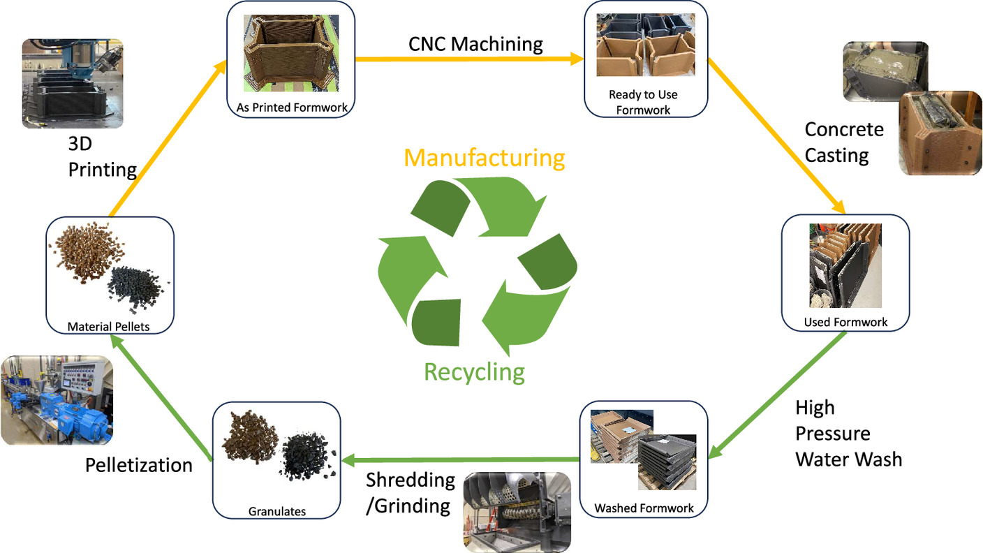
Note material loss was anticipated to occur throughout the recycling iteration. Anticipated losses were anticipated within the manufacturing phase and recycling phase. Manufacturing phase losses resulted from material purge and CNC machining. Recycling phase losses resulted from the shredding/grinding process.
Manufacturing Parameters
The aforementioned materials were subsequently used to manufacture sets of formwork and in addition, hollow hexagonal prisms. These hexagonal prisms were 3D printed together with the forms. A hollow hexagonal shape with a wall thickness of 3.8 cm was chosen so the printed structure was stable enough to stand on its own. Six 30 cm by 34 cm plates were cut from the side walls of the hollow hexagonal prism. Specimens used for tensile testing were cut out from the plates. The mechanical properties of the 3D printed parts were evaluated based on the tensile test of these test specimens.
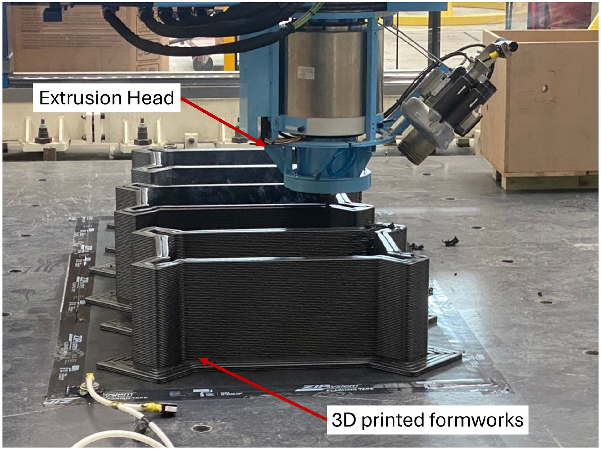
The formwork and hexagonal prisms were manufactured using the Ingersoll MasterPrint large-format 3D printer. All manufacturing used single screw extrusion with a screw diameter of 30 mm and a nozzle diameter of 12.7 mm. Fig. 2 depicts the extrusion head during the baseline CF-ABS formwork manufacturing. It is important to note that the as-printed formworks were manufactured as near-net shapes, meaning that the formworks were manufactured slightly larger than the desired dimensions to allow for postprocessing CNC machining of excess material into smooth formwork faces necessary for concrete casting.
Due to the aforementioned anticipated material loss throughout the recycling process, manufacturing parameters for the formworks could be variable. To ensure consistency within experimental material property characterization, the hexagonal prism manufacturing parameters were kept constant for the baseline and recycled forms, as presented in Table 2.
| Parameter | CF-ABS | WF-aPLA |
|---|---|---|
| Bead width | 20 mm | 20 mm |
| Bead thickness | 5 mm | 5 mm |
| Extrusion rate | ~50 kg/h | ~37 kg/h |
| Extrusion temperature | 247°C | 203°C |
Postprocessing Methods
Following the completion of the AM process, subtractive manufacturing methods were used. These methods included the cutting, machining, and drilling of the forms. First, the forms were cut at the corners into four separate panels. These panels then had the interior faces machined to ensure a smooth surface for casting. Finally, each panel had six 12.7 mm holes drilled into them to allow for formwork assembly.
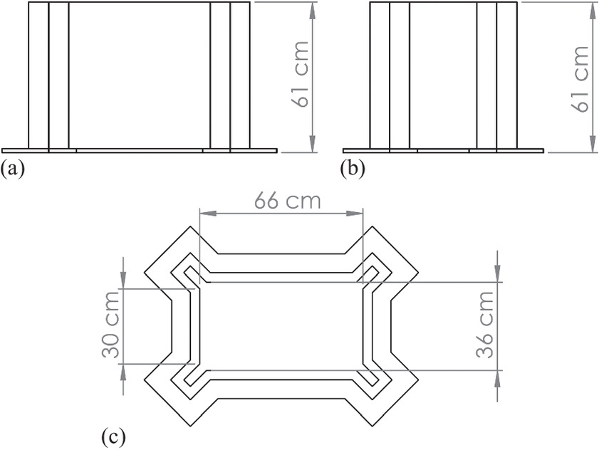
The formworks had a length of 61 cm, a width of 30 cm, and a height of 61 cm. The formworks had a wall thickness of 3.8 cm, which is equivalent to two bead widths, where a bead width refers to the ellipsoid extrudate that is deposited during manufacturing. Fig. 3 details the elevations of the formwork geometry.
Concrete Casting
Concrete was cast inside of the AM composite formwork to simulate the environment in which the application of this research is intended. For the purpose of this work, concrete was only cast one time within the formworks. The number of castings within formwork is highly dependent on the use case. Some typical wooden formworks are single-use, while other traditional formwork systems, such as steel forms, are used many times. Note that the properties of the concrete were not studied or are of interest for this work.
Before casting concrete, assembly of the formwork sets was necessary. Forms were assembled using 25 mm hex-coil bolts and plate washers. Once assembled, a water-based concrete form-release agent was applied to the interior faces of the forms with a brush. A plastic-covered, expanded polystyrene (EPS) void was then coated in the release oil and placed in the center of the form. The EPS void was used to reduce the amount of waste concrete generated during this work. Concrete was then cast around the EPS voids and was allowed to cure for 24 h. Following this curing period, the formwork was disassembled and stripped from the precast concrete part. A 24-hour curing time was selected for this study as is typical in many civil engineering applications; however, it should be noted that demolding time is application-dependent.
Formwork Cleaning
Following casting, the disassembled formwork panels were washed using a 21 MPa, Troy-Bilt pressure washer (Troy-Bilt, Valley City, OH, USA). The washing procedure consisted of laying the panels on a flat, drainable, surface. High-pressure water was applied to the formwork surfaces until no visible cementitious material remained.
Material Shredding and Granulation
Following cleaning, the formwork panels were reduced to granulates using a two-step shredding and granulation process. Formwork panels were fed into a Cumberland MS 40120 shredder with a mesh size of 51 mm in diameter. This material was then fed through a Cumberland 56U granulator with a mesh size of 6 mm in diameter. The granulated mixture was then used as feedstock for pelletization.
Pelletization
A Leistritz ZSE 27-MAXX twin screw extruder with a throughput of 80 kg/h was used to repelletize the recycled formwork panels. The granulate material was extruded at 247°C and 203°C for the CF-ABS and WF-aPLA, respectively. The granulate mixtures were extruded through a die with six 2.5 mm diameter holes. The formed extruded material was dipped into a water bath and then cut to a length of 6 mm.
Material Property Characterization Methods
A holistic approach was taken for the experimental characterization of material properties. Key thermal, mechanical, and physical properties of both materials were monitored throughout the recycling process to characterize material property degradation and understand where in the recycling process this degradation was occurring. Material degradation was based on a comparison of the experimental results of the recycled material with the baseline. Table 3 presents a summary of measured experimental properties and the corresponding method used to obtain the property.
| Material system | Measured property | Test method |
|---|---|---|
| CF-ABS & WF-aPLA | Tensile strength | |
| Tensile modulus | ASTM D3039 | |
| Poisson’s ratio | ||
| Glass transition temperature | ASTM E1356-23 | |
| Effectiveness of washing procedure | ||
| Material impurities | Wang et al. (2019) | |
| Fiber length | Bhandari et al. (2019) | |
| Complex modulus | ||
| Complex viscosity | Walker et al. (2022) | |
| Apparent viscosity | ||
| Molecular weight | Khoda et al. (2023) |
Thermal Property Tests
Using differential scanning calorimetry (DSC), thermogravimetric analysis (TGA), and a rheology study, it was possible to experimentally characterize the glass transition temperature ( ), the effectiveness of the postcasting washing procedure, material purity, complex viscosity and modulus, and apparent viscosity for both material systems.
Differential Scanning Calorimetry
All DSC tests were conducted according to the ASTM E1356 (ASTM 2023) standard test method by implementing a published test procedure (Colón Quintana et al. 2022). Samples were tested using TA Instruments DSC2500 (TA Instruments, New Castel, DE, USA) in TA Tzero aluminum pans. Samples were exposed to two heating ramps, where the ramps consisted of heating samples from 20°C to 200°C at a rate of 10°C/min. The temperature was held at 200°C for one minute between ramps, to ensure the DSC achieved equilibrium. Three samples of each material system were tested to ensure repeatability of results. The was determined using the heat flow curves generated by the second heating ramps, where an average of the midpoint temperatures was taken by the test standard.
Thermogravimetric Analysis
The TGA testing methodology was based on the method used by Wang et al. (2019). Alterations were made to this procedure to adjust for differences in polymers of interest. A TA Instruments Q500 (TA Instruments, New Castel, DE, USA) was selected to test samples. A ramp procedure with a heating rate of 10°C/min to 700°C was used. In addition, samples were tested in a nitrogen atmosphere, with a flow rate of 50 mL/min, to prevent sample oxidization.
Rheology Study
The rheological behavior of samples was measured using a TA Instruments Discovery HR-3 hybrid rheometer (TA Instruments, New Castel, DE, USA). Oscillatory tests were conducted on 8 mm, stainless steel, parallel plates with a 1 mm gap. Shear tests were conducted on 25 mm, stainless steel, parallel plates with the same gap. Testing parameters are presented in Tables 4 and 5, where the test methods were based on those used by Walker et al. (2022), with modifications.
| Test type | Material system | Temperature (°C) | Soak time | Oscillating angular frequency (rad/s) | Sampling rate (points/decade) |
|---|---|---|---|---|---|
| Amplitude sweep | CF-ABS | 247 | 180 | 10.0 | 5 |
| WF-aPLA | 203 | 180 | 10.0 | 5 | |
| Frequency sweep | CF-ABS | 247 | 180 | 100–0.1 | 5 |
| WF-aPLA | 203 | 180 | 100–0.1 | 5 |
| Test type | Material system | Temperature (°C) | Soak time | Shear rate (1/s) | Sampling rate (points/decade) |
|---|---|---|---|---|---|
| Flow sweep | CF-ABS | 247 | 180 | 0.01–10 | 5 |
| WF-aPLA | 203 | 180 | 0.01–10 | 5 |
Note that the applied strain for the oscillatory tests was chosen to be within each material’s linear elastic region. Samples for these tests were molded at extrusion temperature, with a pressure of approximately 14 MPa, using oven-dried material.
Mechanical Property Tests
All tensile testing was conducted per a modified ASTM D3039 (ASTM 2017) with a deviation in specimen geometry to account for the layered structure of the large-format AM specimen and capture a representative unit cell. Tensile coupon specimen geometry is detailed in Table 6.
| Specimen width (mm) | Specimen thickness (mm) | Gauge length (mm) |
|---|---|---|
| 40 | 10 | 50 |
An Instron 8801 Servohydraulic test frame with a 100 kN Intron 2527-111 series load cell (Instron Corporation, Norwood, MA, USA) was selected for specimen testing. A constant head-speed test with a head displacement rate of 2 mm/min was used; where specimens were loaded until failure and digital image correlation (DIC) was used to monitor the strain field over the gauge region of the samples. The DIC system used two 12 MP Basler cameras for image capture of a stochastic black and white pattern painted on the gauge region. A combination of Streampix, LabVIEW, and GOM Correlate software packages was used to trigger and capture images during the tensile tests.
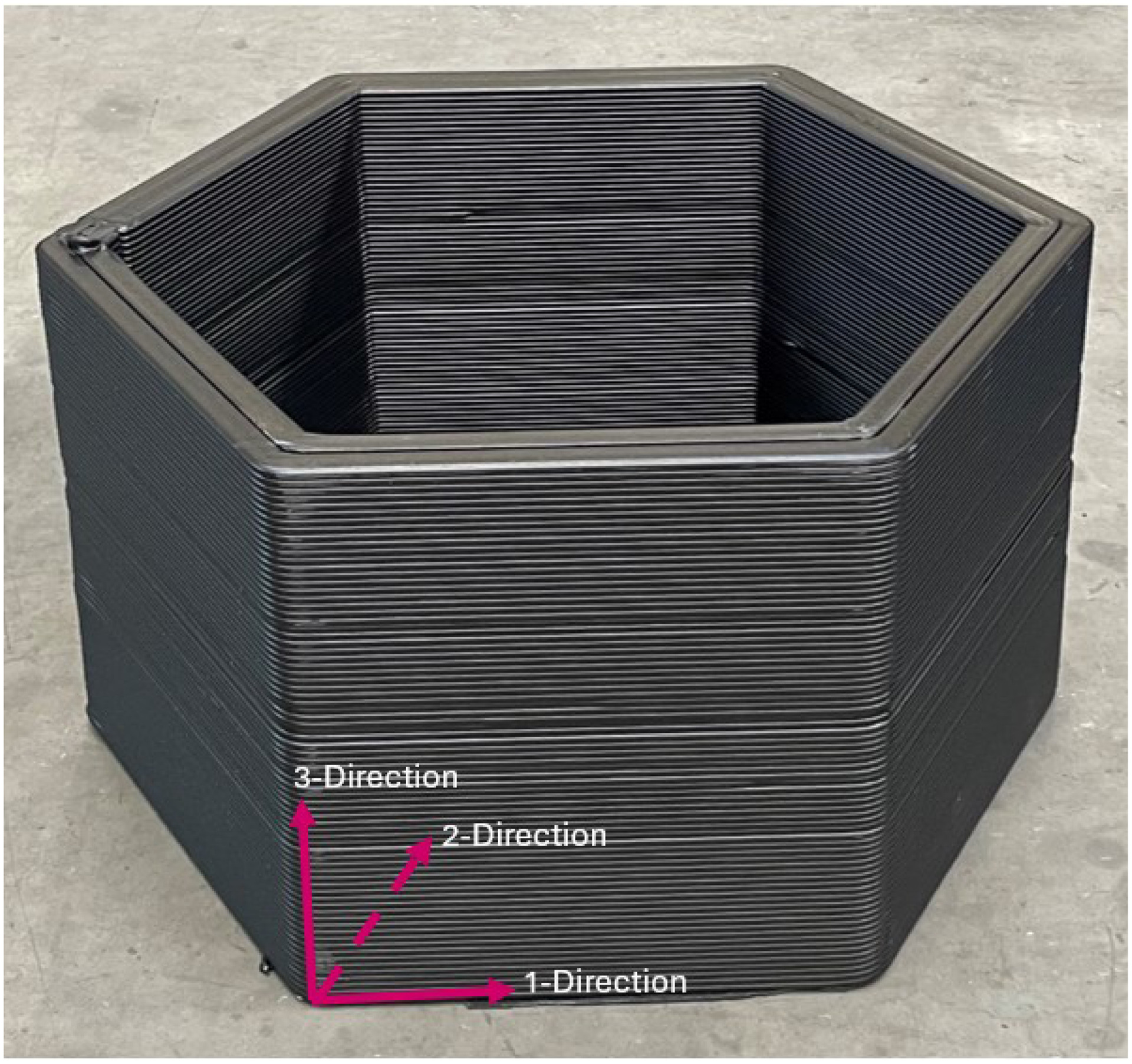
Note that the mechanical properties were tested in two principal directions; the 1-direction and the 3-direction, where the 1-direction corresponds to the direction of deposition of the bead, the 2-direction is transverse to the direction of deposition in the plane of the bead, and the 3-direction is through the thickness of the layer. Fig. 4 illustrates the previously defined directional naming convention.
Physical Property Tests
Physical property testing was conducted to experimentally characterize the lengths of the reinforcing fibers and the molecular weight (MW) of the polymers.
Fiber Length Distribution Determination
The lengths of the reinforcing fibers, for both the carbon fibers (CFs) and the wood flour fibers (WFs), were determined using fiber isolation through a chemical dissolution and scanning electron microscopy (SEM).
Fibers were separated from the composite matrix through chemical dissolution. The procedure for the chemical dissolution was based on a previously established method (Bhandari et al. 2019). CF-ABS and WF-aPLA samples of approximately 0.5 g were placed into a chloroform (CHCl3) bath and then onto a stirring plate. The dissolution vials were then allowed to stir for a period of 24 h, at ambient temperature. The fibers were then filtered and rinsed using dichloromethane (CH2Cl2).
Fiber lengths were measured using a combination of electron microscopy and ImageJ analysis software. Micrographs of the isolated fibers were taken using a Hitachi 3000 scanning electron microscope. All micrographs were taken at × 250 magnification. The fibers captured by these micrographs were subsequently analyzed using ImageJ software. The length and diameters of individual fibers, whose full-lengths were in view, were measured.
Molecular Weight Determination
The MW of both the CF-ABS and the WF-aPLA was measured using gel permeation chromatography (GPC), which is also known as size exclusion chromatography (SEC). An Agilent 1260 Infinity Size Exclusion Chromatography system, equipped with a temperature-controlled refractive index array, was used to perform the tests. Samples of approximately 5 mg were placed into high-performance liquid chromatography grade tetrahydrofuran, which was used as a solvent. Tests were performed between a 1 and 3 mg/mL concentration of polymer in solvent. Samples were then passed through a PTFE syringe filter, prior to injection. Samples were then analyzed with an eluent of tetrahydrofuran at a 1 mL/min flow rate. These tests were performed at 35°C.
Results and Discussion
Initial material property testing results were used to establish the material property baseline. Additional testing following the first material recycling produced results that were used to compare with the baseline.
Thermal Testing Results
Heat flow curves produced from the second heating ramp of the DSC tests were used to establish the glass transition temperature of each material system and can be seen in Fig. 5.
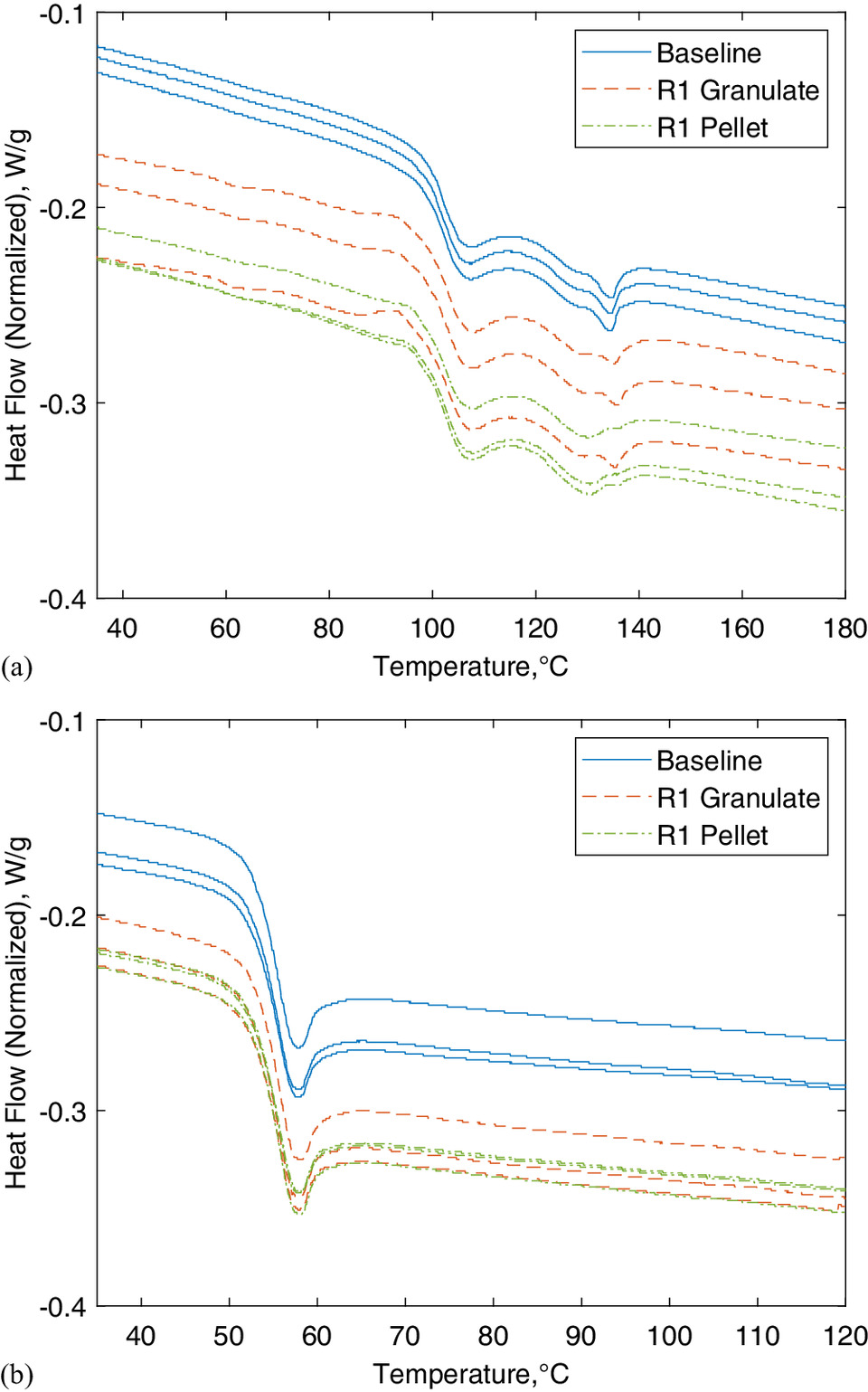
The was determined using the midpoint method of the endothermic peaks. Table 7 presents the midpoint-average values. Note that the CF-ABS samples have two endothermic peaks that both appear to be transition regions: the first at approximately 105°C and the second at approximately 130°C. The literature shows that the first endothermic peak is the true glass transition and that the second endothermic peak is simply a melting point of processed materials used when processing the SAN copolymer. Huseynov et al. (2023) and Billah et al. (2020) both concluded that the second endothermic peak is simply a melting point of an additional processing material. For this work, the first endothermic peak was used to represent the of the CF-ABS material system.
| Material system | Level of processing | Number of tested specimens | Mean glass transition temperature (°C) |
|---|---|---|---|
| Baseline | 3 | 102 | |
| CF-ABS | R1 granulate | 3 | 101.6 |
| R1 pellet | 3 | 101.7 | |
| Baseline | 3 | 54.4 | |
| WF-aPLA | R1 granulate | 3 | 54.3 |
| R1 pellet | 3 | 54.2 |
The baseline of both material systems was comparable to values provided by the material compounder and literature. The baseline WF-aPLA Tg of 54.4°C was approximately 11% lower than the value provided by the material compounder and the baseline CF-ABS of 102°C is comparable to values reported in the literature: where Bin et al. (2018) found the of CF-ABS to be approximately 100°C. Since the of the WF-aPLA is relatively low, the dimensional stability of formworks in hot climates could potentially be of concern. If AM WF-aPLA formworks are to be used in hot climates, where formworks are exposed to a temperature near or at the , surface warping of the formwork is possible, which could result in imperfect cast concrete parts. If this environmental condition is anticipated, casting in a controlled environment, such as an indoor plant, may be preferable. Additional considerations for loss in structural integrity at temperatures higher than would be necessary for the amorphous polymer typically used in 3D printing; specifically when designing parts for applications with high service temperatures. After the first recycling iteration, there were only minor changes to the mean of each material system, where the percent difference between the baseline, R1 granulate, and R1 pellet is less than 0.5%.
Material purity and effectiveness of the washing procedure were established using TGA. The effectiveness of the washing procedure was determined, through a prewash and postwash comparison. Table 8 is a summary of the prewash and postwash samples, where the effectiveness of the washing procedure is assessed by the percentage of residuals.
| Material system | Number of samples | Prewash (%) | Postwash (%) | Mean residuals prewash (%) | Mean residuals postwash (%) |
|---|---|---|---|---|---|
| 3 | 0.00 | 0.24 | |||
| CF-ABS | 3 | 0.77 | 0.00 | 0.51 | 0.08 |
| 3 | 0.75 | 0.00 | |||
| 3 | 5.3 | 0.40 | |||
| WF-aPLA | 3 | 1.4 | 0.47 | 2.60 | 0.29 |
| 3 | 1.1 | 0.00 |
The postcasting washing procedure was proven to be effective, with the measured impurities being less than 0.5% for both material systems. The pre- and postwash comparison showed that both material systems had a reduction of impurities of approximately 80% after washing the forms.
Introduced material impurities were determined through a comparison of the residuals of the baseline pellet and the R1 pellet. Mean residuals, for both the baseline and R1 pellet, are presented in Table 9.
| Material system | Level of processing | Number of samples | Residuals (%) | Mean residuals (average impurity) (%) |
|---|---|---|---|---|
| CF-ABS | Baseline pellet | 3 | 0.00 | |
| 0.00 | 0.00 | |||
| 0.00 | ||||
| CF-ABS | R1 pellet | 3 | 0.00 | |
| 0.00 | 0.00 | |||
| 0.00 | ||||
| WF-aPLA | Baseline pellet | 3 | 0.00 | |
| 0.00 | 0.00 | |||
| 0.00 | ||||
| WF-aPLA | R1 pellet | 3 | 0.05 | |
| 0.12 | 0.12 | |||
| 0.19 |
Impurities introduced after recycling were determined by comparing the residuals of the R1 pellet with those of the baseline pellet. Following the recycling iteration, it was shown that, of the tested samples, the CF-ABS material system had no introduced impurities; whereas the WF-aPLA system had a mean residual introduced impurity of approximately 0.1%.
Rheological properties of both material systems were characterized for the baseline pellet, recycled granulate, and recycled pellet. Complex viscosity and complex modulus of the materials as a function of angular frequency are depicted in Fig. 6.
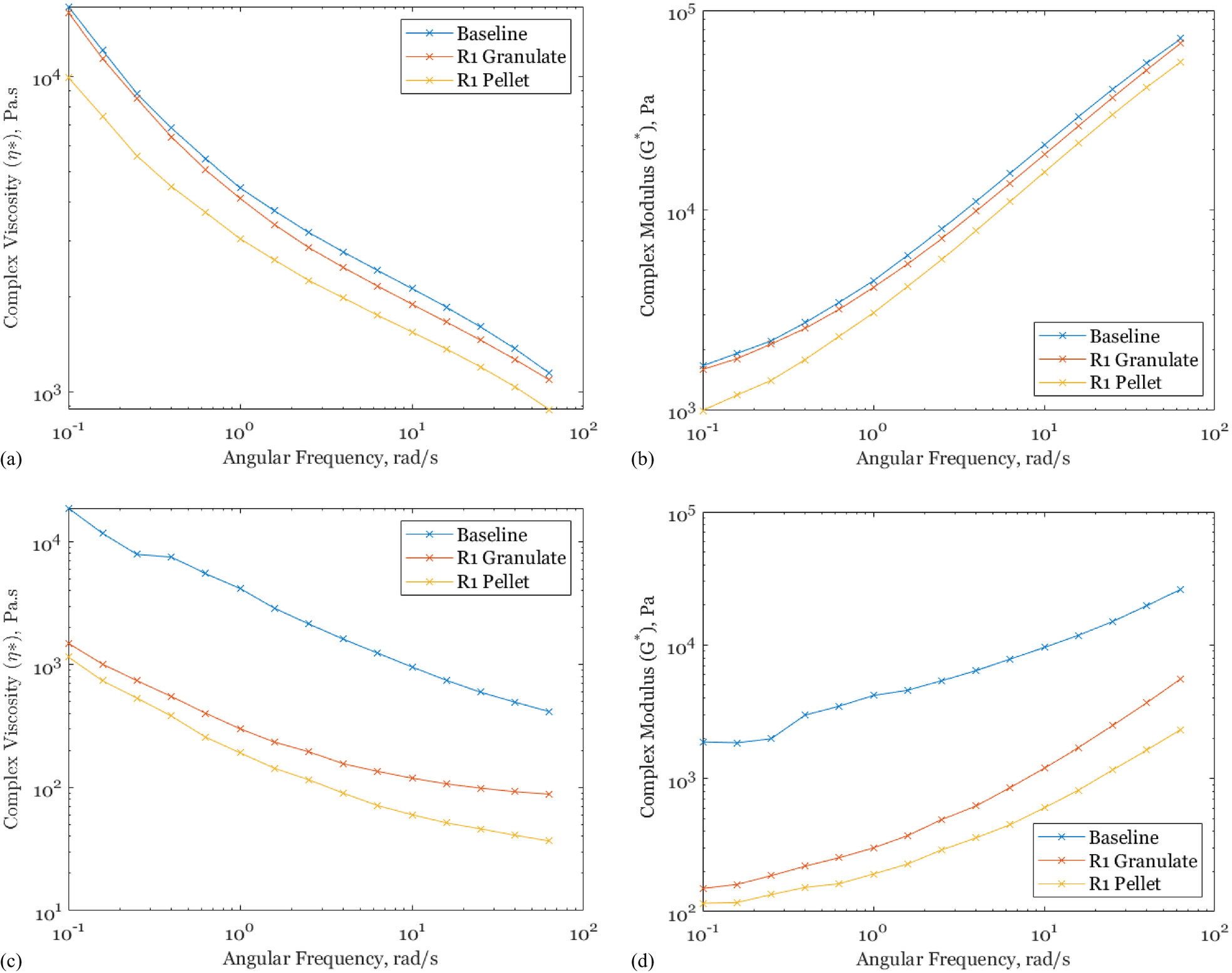
Fig. 6 depicts that both the CF-ABS and WF-aPLA material systems, at each stage of the recycling process, are non-Newtonian, shear-thinning fluids. In addition, Fig. 6 reveals that there are varying degrees of material degradation during the material recycling process. Fig. 6(a) presents that there is minor degradation in the CF-ABS complex viscosity between baseline, R1 granulate, and R1 pellet. Fig. 6(c) reveals that there is a noticeable degradation in the WF-aPLA complex viscosity between the baseline, R1 granulate, and R1 pellet. A similar change is recognized in the complex modulus of each material system. It is important to note that granulates were dried in metal drums in a walk-in oven before the pelletization process, which might have resulted in remaining residual moisture. Since aPLA is more sensitive to the presence of moisture at high processing temperatures due to hydrolysis/chain scission reactions, improving the drying procedure can help minimize the degradation of aPLA in future studies. Figs. 6(b and d) depict the entire viscoelastic behavior of both material systems, revealing that both materials become increasingly more flow resistant with increasing frequency. However, the flow resistance of the materials decreases with additional processing. Table 10 displays that there is no statistical significance between the decrease seen in the CF-ABS complex viscosity and complex modulus throughout the recycling iteration. In addition, Table 10 reveals that there is a statistical significance between the changes seen in the WF-aPLA complex viscosity and complex modulus.
| Material system | Level of reprocessing | Significance level, | Complex Viscosity -value | Complex modulus -Value |
|---|---|---|---|---|
| Baseline | — | — | — | |
| CF-ABS | R1 granulate | 0.05 | 0.84 | 0.85 |
| R1 pellet | 0.05 | 0.21 | 0.51 | |
| Baseline | — | — | — | |
| WF-aPLA | R1 granulate | 0.05 | 0.005 | 0.001 |
| R1 pellet | 0.05 | 0.004 | 0.0003 |
The apparent shear rate of the material at the nozzle can be approximated using (Agassant et al. 2017)where the volumetric flow rate; and the radius of the nozzle. The shear rate at the nozzle ( ) of the CF-ABS and WF-aPLA, according to Eq. (1), is approximately 71.7 and , respectively.
(1)
The shear stress in the material as a function of shear rate is depicted in Fig. 7; note that these stresses are for low shear rates and are not representative of the shear rates experienced by the material during manufacturing.
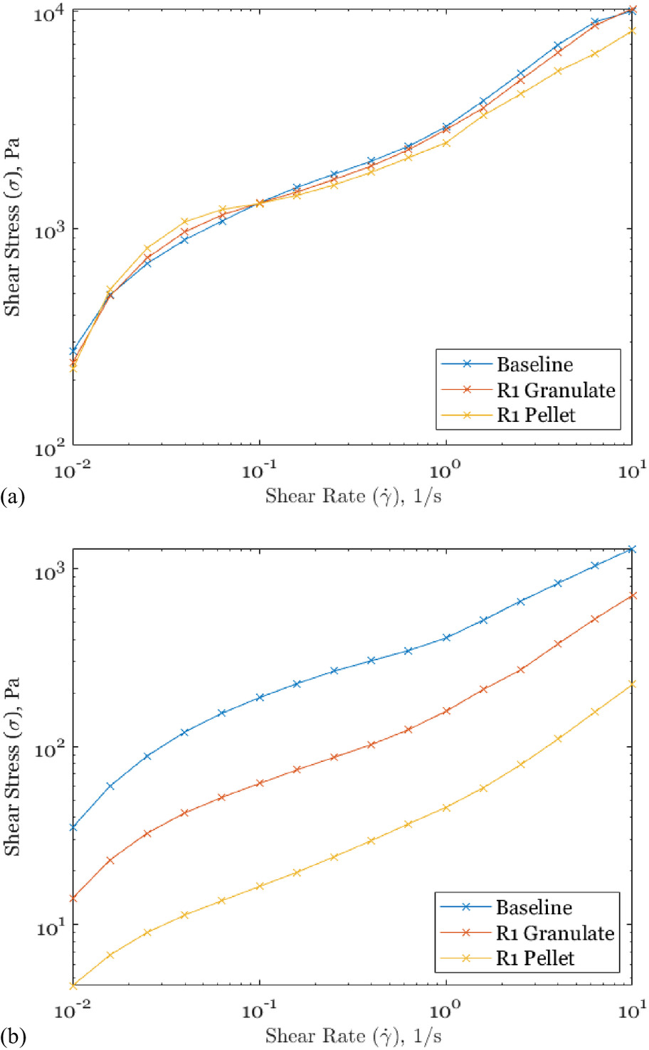
Using the data presented in Fig. 7 and the Herschel–Bulkley (H-B) model, it was possible to obtain the apparent viscosity at the desired shear rates. The H-B model iswhere the consistency index; the yield stress; and the flow behavior index.
(2)
The shear stress values and fitting parameters were obtained through a least squares curve fit; calculated values from this fit are listed in Table 11.
| Material system | Processing level | H-B fitting parameter | Parameter value | Coefficient of determination ( ) |
|---|---|---|---|---|
| Yield stress, | 1,180 | |||
| CF-ABS | Baseline | Consistency index, k | 1,810 | 0.9997 |
| Flow behavior index, n | 0.847 | |||
| Yield stress, | 1,090 | |||
| CF-ABS | R1 granulate | Consistency index, k | 1,750 | 0.9998 |
| Flow behavior index, n | 0.810 | |||
| Yield stress, | 970 | |||
| CF-ABS | R1 pellet | Consistency index, k | 1,620 | 0.9983 |
| Flow behavior index, n | 0.714 | |||
| Yield stress, | 115 | |||
| WF-aPLA | Baseline | Consistency index, k | 314 | 0.9990 |
| Flow behavior index, n | 0.0.581 | |||
| Yield stress, | 51.4 | |||
| WF-aPLA | R1 granulate | Consistency index, k | 107 | 0.9993 |
| Flow behavior index, n | 0.808 | |||
| Yield stress, | 15.0 | |||
| WF-aPLA | R1 pellet | Consistency index, k | 29.9 | 0.9998 |
| Flow behavior index, n | 0.844 |
The apparent viscosity of each material system at the nozzle was calculated using Eq. (3). The calculated values are presented in Table 12.
(3)
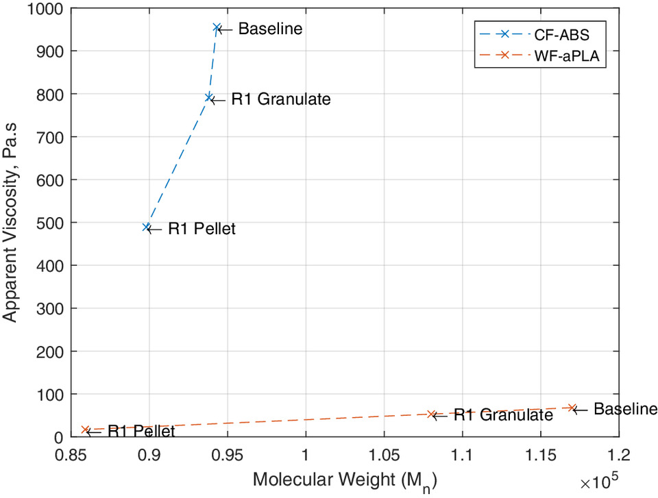
The CF-ABS had less degradation of apparent viscosity between the baseline and R1 results when compared with the WF-aPLA material system. The CF-ABS baseline to R1 granulate has a percent difference of approximately 17% and an approximate difference of 49% between the baseline and R1 pellet. The WF-aPLA baseline to R1 granulate has a percent difference of approximately 22% and an approximate reduction of 75% between the baseline and R1 pellet. These reductions in rheological properties, for each material system, can be correlated to the respective degradation of molecular weight (Bremner et al. 1990; Bernreitner et al. 1992; Chadwick et al. 2004; Bourmaud and Baley 2007; Ares et al. 2010; Yuan et al. 2011). Fig. 8 depicts the correlation between the material apparent viscosity and the MW, showing that the CF-ABS material system is more sensitive to changes in MW compared with the WF-aPLA. Two recent studies, evaluating the recyclability of natural fiber–reinforced composites, explored the effects of multiple recycling iterations on the composite rheological properties, concluding that reductions in material viscosity are products of reductions in polymer molecular weight and reduction in reinforcing fiber length (Rosenstock Völtz et al. 2020; Zhao et al. 2022). The dependency of viscosity on the composite constituent materials indicates that the degradation in viscosity is of concern due to the nocent nature of the thermomechanical recycling process on the reinforcing fibers and polymer matrix, where reductions in material viscosity could pose as a limiting factor. Continued reductions in viscosity at melt temperature would affect the ability of the extruded material to hold its shape (Chu et al. 2022; Bhandari and Lopez-Anido 2023). However, additional studies have been conducted to evaluate the reclamation of material properties after recycling, through the addition of both virgin material and additional additives. One such study focused on the thermomechanical properties of a 3D printed virgin/recycled PLA blend with a chain extender additive (CE), concluding that the incorporation of the CE improved rheological properties including complex viscosity (Cisneros-López et al. 2020). Another study explored the use of mechanical recycling of fused filament fabrication (FFF) 3D printing filaments as a method of waste reduction, focusing on the chemical, thermal, and thermomechanical characterization of both virgin and virgin/recycled PLA blends; finding that viscosity increases with an increased ratio of virgin material to recycled material (Agbakoba et al. 2023).
| Material system | Processing level | Apparent viscosity at the nozzle ( ) |
|---|---|---|
| Baseline | 956 | |
| CF-ABS | R1 granulate | 791 |
| R1 pellet | 489 | |
| Baseline | 68 | |
| WF-aPLA | R1 granulate | 53 |
| R1 pellet | 17 |
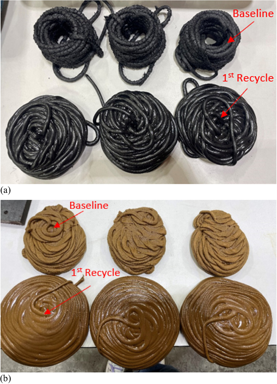
In addition, Fig. 9 provides a physical presentation of alterations in extruded material appearance, texture, and shape following one recycling iteration.
Mechanical Testing Results
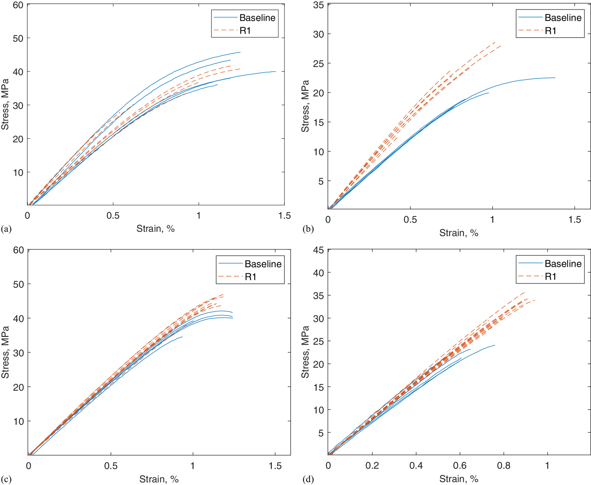
The tensile properties of the material systems investigated are presented in Table 13. The corresponding stress–strain relationships of the materials are depicted in Fig. 10.
| Material system | Processing level | Testing direction | Number of samples | Average tensile modulus (MPa) (COV) | Average tensile strength (MPa) (COV) | Poisson’s ratio (COV) |
|---|---|---|---|---|---|---|
| Baseline | 1-Direction | 5 | 4,890 (11%) | 40.5 (10%) | 0.36 (4%) | |
| CF-ABS | Baseline | 3-Direction | 4 | 2,450 (0.46%) | 19.7 (11%) | 0.18 (2%) |
| R1 print | 1-Direction | 7 | 4,820 (11%) | 33.7 (21%) | 0.38 (7.5%) | |
| R1 print | 3-Direction | 8 | 3,260 (4.7%) | 20.1 (33%) | 0.26 (25%) | |
| Baseline | 1-Direction | 5 | 4,290 (1.2%) | 39.6 (5.2%) | 0.35 (0.83%) | |
| WF-aPLA | Baseline | 3-Direction | 5 | 3,730 (5.7%) | 23.7 (13%) | 0.30 (5.5%) |
| R1 print | 1-Direction | 9 | 4,480 (3.6%) | 40.7 (13%) | 0.35 (1.8%) | |
| R1 print | 3-Direction | 11 | 4,030 (2.8%) | 31.2 (11%) | 0.32 (4.7%) |
The measured baseline tensile properties revealed that both the CF-ABS and WF-aPLA materials were stronger in the 1-direction than the 3-direction; this holds for the recycled material systems. The materials are expected to have a higher strength and modulus in the 1-direction when compared with the 3-direction, due to the preferential alignment of fibers. In addition, the 3-direction contains “welding lines” formed by incomplete polymer diffusion along the deposited layers.
Table 13 reveals that the mean tensile strength and mean tensile modulus for the CF-ABS material system, in the 1-direction, decrease after the material is recycled. Following recycling, the mean tensile modulus decreased by approximately 1.4% and the mean tensile strength decreased by approximately 18%. The decrease in mechanical performance of the CF-ABS, in the 1-direction, can be attributed to the fiber attrition of the carbon fibers. Hwang and Cho (2019) concluded that the mechanical performance of CF-ABS was highly dependent on the aspect ratio of the fiber reinforcement. In addition, Table 13 also reveals that the mean tensile strength and mean tensile modulus of the WF-aPLA, in the 1-direction, increases by 2.7% and 4.3%, respectively. Increased performance of the WF-aPLA in the 1-direction can be attributed to the increased aspect ratio of the wood flour fibers; resulting from further fibrillation during the recycling process. A study conducted by Robertson et al. (2013) found that thermoplastic composites reinforced with natural fibers displayed higher strength when reinforced with large aspect ratio fibers.
Table 13 also reveals that the mean tensile strength and mean tensile modulus of both material systems, in the 3-direction, increases after recycling, where the CF-ABS was approximately 2% stronger after recycling and the WF-aPLA was approximately 27% stronger, in the 3-direction, after recycling. The observed increase in 3-direction tensile strength can be attributed to the increased interlaminar adhesion between the layers, as a result of increased molecular diffusion through the layers (Bhandari et al. 2019).
Physical Test Results
A matrix dissolution was used to isolate the reinforcing fibers from the thermoplastic matrices to be measured. Fiber length distributions and corresponding Weibull fits are depicted in Fig. 11.
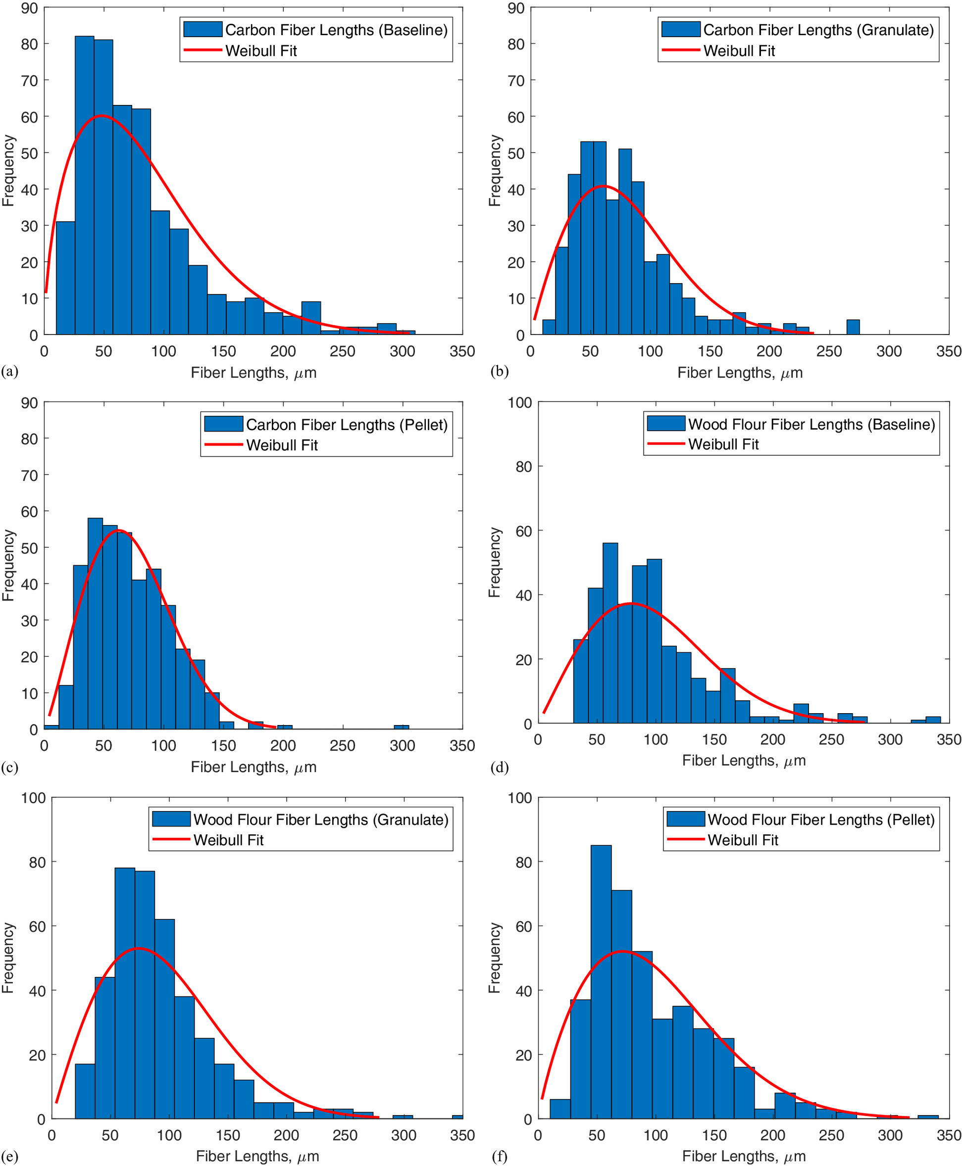
Figs. 11(a–c) depict the fiber length distributions for the carbon fibers (CFs) for increasing levels of processing. Figs. 11(a–c) depict that additional processing of the CFs creates a more normal distribution of fiber lengths, with increasing density of the shorter lengths. Figs. 11(d–f) depict that the wood flour fibers (WFs) distribution does not increase in normality and the distribution with a right skew remains. In addition, Fig. 11 depicts the Weibull fit for each material system’s corresponding level of processing. Table 14 lists two fitting parameters for the Weibull distribution.
| Material system | Level of processing | Scale | Shape |
|---|---|---|---|
| Baseline pellet | 91.7 | 1.57 | |
| CF-ABS | R1 granulate | 88.7 | 1.92 |
| R1 pellet | 82.2 | 2.20 | |
| Baseline pellet | 109 | 2.08 | |
| WF-aPLA | R1 granulate | 107 | 1.96 |
| R1 pellet | 112 | 1.81 |
In addition to fiber length determination, aspect ratios were also measured throughout the recycling iteration. The significance of the change in aspect ratio between the baseline and the recycled material was determined using analysis of variance (ANOVA) -tests.
Table 15 reveals that the aspect ratio of the CFs decreases with additional processing, which was to be expected due to the chopping and shredding nature of the recycling process. Table 15 also presents that there is no statistical significance between the difference in the CF baseline and R1 granulate. However, there is a statistical significance between the difference in the CF baseline and the R1 pellet, which is revealed by the -value being less in value than the level of significance. This means that the CFs maintain their lengths during the purely mechanical portion of the recycling process, with only minor degradation; and the majority of fiber attrition is happening in the additional processing step of material extrusion and pelletization.
| Material system | Level of processing | Aspect ratio | Significance level ( ) | -Value |
|---|---|---|---|---|
| Baseline pellet | 10.6 | — | — | |
| CF-ABS | R1 granulate | 9.91 | 0.05 | 0.101 |
| R1 pellet | 9.11 | 0.05 | ||
| Baseline pellet | 2.35 | — | — | |
| WF-aPLA | R1 granulate | 2.82 | 0.05 | |
| R1 pellet | 3.02 | 0.05 |
Interestingly, the WF aspect ratio increased with material recycling. Table 15 reveals that the increase in WF aspect ratio between the baseline and the R1 granulate, as well as the baseline and R1 pellet, is statistically significant since the -values are significantly smaller than the significance level. This means that the WFs are fibrillating and becoming more fiberlike, rather than being particulates.
GPC was used to quantify the molecular weight of the compounded material at multiple stages within the recycling iteration. Results from the GPC analysis are presented in Table 16.
| Composite material | Polymer | Processing level | Mean molecular weight ( ) (g/mol) | Average peak molecular weight ( ) (g/mol) | Polydispersity (PD) |
|---|---|---|---|---|---|
| Baseline | 94,300 | 190,000 | 1.84 | ||
| CF-ABS | ABS | R1 granulate | 93,800 | 189,000 | 1.84 |
| R1 pellet | 89,800 | 187,000 | 1.89 | ||
| Baseline | 117,000 | 202,000 | 1.65 | ||
| WF-aPLA | aPLA | R1 granulate | 108,000 | 191,000 | 1.63 |
| R1 pellet | 85,900 | 172,000 | 1.73 |
The ABS saw a reduction in average mean molecular weight of approximately 0.5%, between the baseline and the R1 granulate, and a reduction of approximately 5% between the baseline and R1 pellet. The polydispersity (PD) of the ABS remained unchanged after the shredding/granulation process. However, the PD of the ABS increased by approximately 3% after the repelletization of the recycled granulate material; meaning that the molecular weight distribution of the ABS becomes broader after recycling. The amorphous PLA saw a reduction in average mean molecular weight of approximately 8% between the baseline and R1 granulate, and a reduction of approximately 31% between the baseline and the R1 pellet. In addition, the PD of the aPLA increased by approximately 5% following the recycling process. If the observed negative trend of MW continues throughout successive recycling interactions, the composite material will no longer be printable.
Material Quantity Loss
As anticipated, material loss was noted between the baseline print and the R1 print. The CF-ABS and WF-aPLA systems experienced reductions in material weight of approximately 50 kg/system. In addition to the material loss within the recycling process, there was an allocation of material for the hexagonal prisms. The total reduction in material resulted in a reduction in the number of forms that could be printed per material system. The baseline had a total of ten 3D printed forms, five forms per material system. The R1 cycle had a total of six 3D printed forms, three forms per material system.
Conclusions
The following conclusions were drawn from the study.
A procedure was established and effectively implemented for the mechanical recycling of 3D printed formworks after use for casting precast concrete parts. The postcasting washing with high-pressure water was proven to be effective, as revealed through minimal introduction of residual weight. Mechanical shredding and granulation followed by thermomechanical pelletization was found to be effective in producing uniform recycled feedstock pellets that could be used for 3D printing new formwork for manufacturing precast concrete parts. The recycled 3D printed formwork was used successfully to cast precast concrete parts.
The efficacy of thermomechanical recycling was determined by evaluating the changes in physical, thermal, and mechanical properties of the recycled polymer composites. The thermal properties of the recycled polymer composites remained largely unaffected due to recycling. The was relatively unchanged after recycling, with both material systems seeing a reduction in transition temperature of approximately 0.5%.
The mechanical properties of both materials were greater in the 1-direction when compared with the 3-direction. However, following the material recycling, the CF-ABS saw a reduction in both average strength and average modulus in both directions. Recycled ABS polymer had the mean molecular weight reduced by 4.8%, with the majority of degradation occurring during the extrusion and pelletization processes of the recycling. Reinforcing short carbon fibers showed fiber length shortening and subsequent decrease in fiber aspect ratio.
Recycled WF-aPLA showed an increase in both average strength and modulus in both directions. The WF-aPLA material system exhibited a decrease of 27% in mean molecular weight. As mentioned previously in the manuscript, improving the drying procedure can help minimize the degradation of aPLA in future studies, since aPLA is more sensitive to the presence of moisture at high processing temperatures due to hydrolysis/chain scission reactions. Wood fibers underwent morphologic changes during the recycling process. However, these changes did not amount to fiber degradation. Instead, during the recycling process, the wood fibers were further fibrillated and ended up having a higher aspect ratio of 3.02 compared with an aspect ratio of 2.35 for original fibers.
Dynamic rheologic properties of the CF-ABS, including complex viscosity and complex modulus, had minor decreases with each additional processing step. However, these decreases were shown to be statistically insignificant. The WF-aPLA material system significantly decreases in complex modulus and complex viscosity with each additional processing step. It was also found that after material recycling, the viscosity decreased by approximately 49% and 75% for the recycled CF-ABS and WF-aPLA polymer composites, respectively.
The loss of material during manufacturing and recycling was quantified to estimate the number of formworks to be 3D printed following recycling. In addition, further work is needed to evaluate the number of times the material can effectively be recycled.
Data Availability Statement
Some or all data, models, or code that support the findings of this study are available from the corresponding author upon reasonable request.
Acknowledgments
This work was supported in part by funding from UT-Battelle LLC with the U.S. Department of Energy under contract DE-AC05-00OR22725 (subcontract # 4000174848), and by funding from the Transportation Infrastructure Durability Center (TIDC) with the U.S. Department of Transportation’s University Transportation Centers Program under grant 69A3551847101. The work presented in this paper was completed as part of an M.S. thesis undertaken by the first author at the University of Maine advised by Dr. Roberto Lopez-Anido and Dr. Sunil Bhandari. The authors would like to thank Dr. W. Gramlich and Mr. D. Bones of the Department of Chemistry at the University of Maine for their help with the chemical dissolutions, and Dr. S. Shams Es-haghi of the Advanced Structures and Composites Center at the University of Maine for his help with the rheology study.
References
Adamcová, D., and M. D. Vaverková. 2016. “New polymer behavior under the landfill conditions.” Waste Biomass Valorization 7 (6): 1459–1467. https://doi.org/10.1007/s12649-016-9542-0.
Agassant, J., P. Avenas, P. Carreau, B. Vergnes, and M. Vincent. 2017. Polymer processing: Principles and modeling. Munich, Germany: Carl Hanser Verlag GmbH & Company KG. https://books.google.com/books?id=pigvDwAAQBAJ.
Agbakoba, V. C., N. Webb, E. Jegede, R. Phillips, S. P. Hlangothi, and M. J. John. 2023. “Mechanical recycling of waste PLA generated from 3D printing activities: Filament production and thermomechanical analysis.” Macromol. Mater. Eng. 309 (8): 2300276. https://doi.org/10.1002/mame.v309.8.
Ares, A., R. Bouza, S. G. Pardo, M. J. Abad, and L. Barral. 2010. “Rheological, mechanical and thermal behaviour of wood polymer composites based on recycled polypropylene.” J. Polym. Environ. 18 (3): 318–325. https://doi.org/10.1007/s10924-010-0208-x.
Armstrong, K. O., D. Kamath, X. Zhao, M. L. Rencheck, H. Tekinalp, M. Korey, D. Hun, and S. Ozcan. 2023. “Life cycle cost, energy, and carbon emissions of molds for precast concrete: Exploring the impacts of material choices and additive manufacturing.” Resour. Conserv. Recycl. 197: 107117. https://doi.org/10.1016/j.resconrec.2023.107117.
ASTM. 2017. Standard test method for tensile properties of polymer matrix composite materials. ASTM D3039/D3039M-17. West Conshohocken, PA: ASTM.
ASTM. 2023. Standard test method for assignment of the glass transition temperatures by differential scanning calorimetry. ASTM E1356-23. West Conshohocken, PA: ASTM.
Beltrán González, F., M. Arrieta, E. Moreno, G. Gaspar, L. Martínez, R. Carrasco-Gallego, S. Yáñez, D. Hidalgo-Carvajal, M. U. de la Orden, and J. Urreaga. 2021. “Evaluation of the technical viability of distributed mechanical recycling of PLA 3D printing wastes.” Polymers 13 (8): 1247. https://doi.org/10.3390/polym13081247.
Bernatas, R., S. Dagreou, A. Despax-Ferreres, and A. Barasinski. 2021. “Recycling of fiber reinforced composites with a focus on thermoplastic composites.” Cleaner Eng. Technol. 5: 100272. https://doi.org/10.1016/j.clet.2021.100272.
Bernreitner, K., W. Neißl, and M. Gahleitner. 1992. “Correlation between molecular structure and rheological behaviour of polypropylene.” Polym. Test. 11 (2): 89–100. https://doi.org/10.1016/0142-9418(92)90040-I.
Bhandari, S., R. Lopez-Anido, and J. Anderson. 2020. “Large scale 3D printed thermoplastic composite forms for precast concrete structures.” In Proc., ITHEC 2020, 5th Int. Conf. & Exhibition on Thermoplastic Composites, 182–187. Bremen, Germany: Congress Bremen & Messe Bremen.
Bhandari, S., and R. A. Lopez-Anido. 2023. “Coupled thermo-mechanical numerical model to minimize risk in large-format additive manufacturing of thermoplastic composite designs.” Prog. Addit. Manuf. 8 (3): 393–407. https://doi.org/10.1007/s40964-022-00349-9.
Bhandari, S., R. A. Lopez-Anido, and D. J. Gardner. 2019. “Enhancing the interlayer tensile strength of 3D printed short carbon fiber reinforced PETG and PLA composites via annealing.” Addit. Manuf. 30: 100922.
Bhandari, S., R. A. Lopez-Anido, F. S. Rojas, and A. LeBihan. 2022. “Design and manufacture of precast concrete formworks using polymer extrusion-based large-scale additive manufacturing and postprocessing.” In Progress in additive manufacturing, 1–13. Berlin: Springer.
Billah, K. M. M., F. A. R. Lorenzana, N. L. Martinez, R. B. Wicker, and D. Espalin. 2020. “Thermomechanical characterization of short carbon fiber and short glass fiber-reinforced ABS used in large format additive manufacturing.” Addit. Manuf. 35: 101299.
Bin, Y., X. Li, J. An, Z. Jiang, and J. Yang. 2018. “Interfacial and glass transition properties of surface-treated carbon fiber reinforced polymer composites under hygrothermal conditions.” Eng. Sci. 2: 67–73.
Bourmaud, A., and C. Baley. 2007. “Investigations on the recycling of hemp and sisal fibre reinforced polypropylene composites.” Polym. Degrad. Stab. 92 (6): 1034–1045. https://doi.org/10.1016/j.polymdegradstab.2007.02.018.
Bremner, T., A. Rudin, and D. G. Cook. 1990. “Melt flow index values and molecular weight distributions of commercial thermoplastics.” J. Appl. Polym. Sci. 41 (7–8): 1617–1627. https://doi.org/10.1002/app.07.v41:7/8.
Burger, J., E. Lloret-Fritschi, M. Akermann, D. Schwendemann, F. Gramazio, and M. Kohler. 2023. “Circular formwork: Recycling of 3D printed thermoplastic formwork for concrete.” Technol. Archit. Des. 7 (2): 204–215. https://doi.org/10.1080/24751448.2023.2245724.
Chadwick, J. C., F. P. T. J. van der Burgt, S. Rastogi, V. Busico, R. Cipullo, G. Talarico, and J. J. R. Heere. 2004. “Influence of Ziegler-Natta catalyst regioselectivity on polypropylene molecular weight distribution and rheological and crystallization behavior.” Macromolecules 37 (26): 9722–9727. https://doi.org/10.1021/ma048108c.
Chilton, T., S. Burnley, and S. Nesaratnam. 2010. “A life cycle assessment of the closed-loop recycling and thermal recovery of post-consumer PET.” Resour. Conserv. Recycl. 54 (12): 1241–1249. https://doi.org/10.1016/j.resconrec.2010.04.002.
Chu, J. S., S. C. Koay, M. Y. Chan, H. L. Choo, and T. K. Ong. 2022. “Recycled plastic filament made from post-consumer expanded polystyrene and polypropylene for fused filamant fabrication.” Polym. Eng. Sci. 62 (11): 3786–3795. https://doi.org/10.1002/pen.v62.11.
Cisneros-López, E. O., A. K. Pal, A. U. Rodriguez, F. Wu, M. Misra, D. F. Mielewski, A. Kiziltas, and A. K. Mohanty. 2020. “Recycled poly(lactic acid)–based 3D printed sustainable biocomposites: A comparative study with injection molding.” Mater. Today Sustainability 7–8: 100027. https://doi.org/10.1016/j.mtsust.2019.100027.
Colón Quintana, J. L., L. Slattery, J. Pinkham, J. Keaton, R. A. Lopez-Anido, and K. Sharp. 2022. “Effects of fiber orientation on the coefficient of thermal expansion of fiber-filled polymer systems in large format polymer extrusion-based additive manufacturing.” Materials 15 (8): 2764. https://doi.org/10.3390/ma15082764.
Cress, A., J. Huynh, E. Anderson, R. O’neill, Y. Schneider, and Ö. Keleş. 2020. “Effect of recycling on the mechanical behavior and structure of additively manufactured acrylonitrile butadiene styrene (ABS).” J. Cleaner Prod. 279: 123689. https://doi.org/10.1016/j.jclepro.2020.123689.
Hamad, K., and F. Deri. 2013. “Recycling of waste from polymer materials: An overview of the recent works.” Polym. Degrad. Stab. 98 (12): 2801–2812. https://doi.org/10.1016/j.polymdegradstab.2013.09.025.
Hamilton, J. D., K. H. Reinert, J. V. Hagan, and W. V. Lord. 1995. “Polymers as solid waste in municipal landfills.” J. Air Waste Manage. Assoc. 45 (4): 247–251. https://doi.org/10.1080/10473289.1995.10467364.
Han, D., H. Yin, M. Qu, J. Zhu, and A. Wickes. 2020. “Technical analysis and comparison of formwork-making methods for customized prefabricated buildings: 3D printing and conventional methods.” J. Archit. Eng. 26 (2): 04020001. https://doi.org/10.1061/(ASCE)AE.1943-5568.0000397.
Hasan, M. R., I. J. Davies, A. Pramanik, M. John, and W. K. Biswas. 2024. “Potential of recycled PLA in 3D printing: A review.” Sustainable Manuf. Serv. Econ. 3: 100020.
Huseynov, O., S. Hasanov, and I. Fidan. 2023. “Influence of the matrix material on the thermal properties of the short carbon fiber reinforced polymer composites manufactured by material extrusion.” J. Manuf. Processes 92: 521–533. https://doi.org/10.1016/j.jmapro.2023.02.055.
Hwang, D., and D. Cho. 2019. “Fiber aspect ratio effect on mechanical and thermal properties of carbon fiber/ABS composites via extrusion and long fiber thermoplastic processes.” J. Ind. Eng. Chem. 80: 335–344. https://doi.org/10.1016/j.jiec.2019.08.012.
ISO. 2008. Plastics - guidelines for the recovery and recycling of plastics waste. Standard. Geneva: ISO.
Jagadeesh, P., S. Mavinkere Rangappa, S. Siengchin, M. Puttegowda, S. M. K. Thiagamani, G. Rajeshkumar, M. Hemath Kumar, O. P. Oladijo, V. Fiore, and M. M. Moure Cuadrado. 2022. “Sustainable recycling technologies for thermoplastic polymers and their composites: A review of the state of the art.” Polym. Compos. 43 (9): 5831–5862. https://doi.org/10.1002/pc.v43.9.
Jipa, A., M. Aghaei Meibodi, R. Giesecke, D. Shammas, M. Leschok, M. Bernhard, and B. Dillenburger. 2018. “3D-printed formwork for prefabricated concrete slabs.” In Proc., 1st Int. Conf. on 3D Construction Printing, 1–9. Zurich, Switzerland: ETH Zurich, Digital Building Technologies (ITA).
Jipa, A., and B. Dillenburger. 2021. “3D printed formwork for concrete: State-of-the-art, opportunities, challenges, and applications.” 3D Print. Addit. Manuf. 9 (2): 84–107. https://doi.org/10.1089/3dp.2021.0024.
Khoda, B., W. Gramlich, S. N. Shovon, I. Khalil. 2023. “Effect of molecular weight on polymer solution facilitated transfer of non-Brownian particles.” Prog. Org. Coat. 176: 107394.
Korey, M., et al. 2023. “Recycling polymer composite granulate/regrind using big area additive manufacturing.” Composites, Part B 256: 110652. https://doi.org/10.1016/j.compositesb.2023.110652.
Lopez-Anido, R., W. Davids, S. Bhandari, C. Sheltra, D. F., Jr. Erb, and B. Abdel-Magid. 2022. “Overview of thermoplastic composites in bridge applications.” In Proc., Structural Faults and Repair 2022 & European Bridge Conf. 2022, 1–13. Edinburgh, Scotland: ECS.
Mikula, K., D. Skrzypczak, G. Izydorczyk, J. Warchoł, K. Moustakas, K. Chojnacka, and A. Witek-Krowiak. 2021. “3D printing filament as a second life of waste plastics—A review.” Environ. Sci. Pollut. Res. 28 (10): 12321–12333. https://doi.org/10.1007/s11356-020-10657-8.
Moreno Nieto, D., V. Casal López, and S. I. Molina. 2018. “Large-format polymeric pellet-based additive manufacturing for the naval industry.” Addit. Manuf. 23: 79–85.
Peeters, B., N. Kiratli, and J. Semeijn. 2019. “A barrier analysis for distributed recycling of 3D printing waste: Taking the maker movement perspective.” J. Cleaner Prod. 241: 118313. https://doi.org/10.1016/j.jclepro.2019.118313.
Ragaert, K., L. Delva, and K. Van Geem. 2017. “Mechanical and chemical recycling of solid plastic waste.” Waste Manage. (Oxford) 69: 24–58. https://doi.org/10.1016/j.wasman.2017.07.044.
Robertson, N. M., J. A. Nychka, K. Alemaskin, and J. D. Wolodko. 2013. “Mechanical performance and moisture absorption of various natural fiber reinforced thermoplastic composites.” J. Appl. Polym. Sci. 130 (2): 969–980. https://doi.org/10.1002/app.v130.2.
Rosenstock Völtz, L., I. Di Guiseppe, S. Geng, and K. Oksman. 2020. “The effect of recycling on wood-fiber thermoplastic composites.” Polymers 12 (8): 1750. https://doi.org/10.3390/polym12081750.
Shah, J., B. Snider, T. Clarke, S. Kozutsky, M. Lacki, and A. Hosseini. 2019. “Large-scale 3D printers for additive manufacturing: Design considerations and challenges.” Int. J. Adv. Manuf. Technol. 104 (9): 3679–3693. https://doi.org/10.1007/s00170-019-04074-6.
Teizer, J., A. Blickle, T. King, O. Leitzbach, and D. Guenther. 2016. “Large scale 3D printing of complex geometric shapes in construction.” In Proc., 33th Int. Symposium on Automation and Robotics in Construction, 836–843. Red Hook, NY: Curran Associates, Inc.
Walker, R., V. Kunc, C. Duty, and C. Helton. 2022. Rheological evaluation of printability for recycled carbon fiber acrylonitrile butadiene styrene. Rep. Oak Ridge, TN: Oak Ridge National Laboratory.
Wang, L., J. Palmer, M. Tajvidi, D. J. Gardner, and Y. Han. 2019. “Thermal properties of spray-dried cellulose nanofibril-reinforced polypropylene composites from extrusion-based additive manufacturing.” J. Therm. Anal. Calorim. 136 (3): 1069–1077. https://doi.org/10.1007/s10973-018-7759-9.
Yuan, M., J. A. Galloway, R. J. Hoffman, and S. Bhatt. 2011. “Influence of molecular weight on rheological, thermal, and mechanical properties of peek.” Polym. Eng. Sci. 51 (1): 94–102. https://doi.org/10.1002/pen.v51.1.
Zhao, X., et al. 2022. “Recycling of natural fiber composites: Challenges and opportunities.” Resour. Conserv. Recycl. 177: 105962. https://doi.org/10.1016/j.resconrec.2021.105962.
Information & Authors
Information
Published In

Journal of Composites for Construction
Volume 28 • Issue 6 • December 2024
Copyright
This work is made available under the terms of the Creative Commons Attribution 4.0 International license, https://creativecommons.org/licenses/by/4.0/.
History
Received: Jan 30, 2024
Accepted: Jul 15, 2024
Published online: Sep 24, 2024
Published in print: Dec 1, 2024
Discussion open until: Feb 24, 2025
Authors
Metrics & Citations
Metrics
Citations
Download citation
If you have the appropriate software installed, you can download article citation data to the citation manager of your choice. Simply select your manager software from the list below and click Download.