Built-Up Press Brake-Formed Tub Girders
Publication: Journal of Bridge Engineering
Volume 28, Issue 12
Abstract
This paper presents built-up press brake-formed tub girders (PBTGs) as a new approach for the fabrication of resilient, short-span steel bridges. In contrast to existing PBTGs that are cold bent from a single steel plate, this is a built-up system in which webs are cold bent and bolted to separate, flat bottom and top flange plates. It offers enhanced versatility, as this is a “kit-of-parts” where different sizes of components can be used to achieve required capacities or span lengths (e.g., thicker bottom flanges for negative moment regions, deeper webs for longer spans). Using built-up sections joined by bolts provides internal member redundancy, as crack propagation between components is arrested. The objectives of this paper are to: (1) introduce the system including design details; (2) numerically demonstrate its feasibility through the finite element modeling of two demonstration bridges; and (3) investigate the internal redundancy by evaluating behavior when a flange or web is abruptly lost. Results indicate the viability and redundancy of the system for simple and two-span continuous bridges.
Introduction
This research introduces built-up press brake-formed tub girders (PBTGs) (Fig. 1) as a means of fabricating short-span steel bridges with enhanced resiliency. Recently, there has been a major focus on accelerated bridge construction (ABC) with the aim of reducing traffic disruption. In comparison, there has been relatively little attention given to advancing fabrication techniques, particularly in the case of steel girder bridges which typically require unique shop drawings, complex fabrication techniques, and customization. This research is focused on developing design approaches and fabrication strategies to reduce the time for steel girder fabrication. It also seeks to take advantage of adjacent industries—in this case, transmission pole manufacturers—that are experienced in the steel supply chain but do not fabricate bridge girders.

Currently, prestressed concrete girders dominate the short-span bridge market, since they can be fabricated on demand, without long lead times on materials. A major downside of prestressed girders is that they are comparatively heavy, often requiring large cranes and special trucking and permits for erection. This research seeks to develop steel bridge fabrication techniques that are competitive with prestressed concrete girders but have advantages in transport and erection.
Typical short-span steel alternatives include wide flange rolled beam or plate girder systems. Wide flange beams are appealing, as they are simple to design and fabricate (FHWA 2015a; Shergalis and Law 2016). These are appropriate for simple spans up to 30.5 m (100 ft) or continuous spans up to 36.6 m (120 ft) (FHWA 2015b), but become inefficient for spans exceeding 24.4 m (80 ft) (Shergalis and Law 2016). Despite being heavier than plate girders, rolled sections are less expensive for short spans due to reduced complexity of fabrication compared with plate girders (FHWA 2015b). Additionally, stiffeners are often not required for rolled beams, and diaphragms can also be rolled sections (FHWA 2015b). Plate girders become more economical for spans exceeding 38.1 m (125 ft) (FHWA 2015b). However, plate girders are expensive to fabricate and fabrication time would be of the order of 24 to 30 weeks.
Recent advances in rapid fabrication and ABC for steel girder bridges include short-span [up to 30.5 m (100 ft)] PBTGs and folded steel plate girders (FSPG), which are cold bent girders formed from a single piece of plate steel (Short Span Steel Bridge Alliance 2020b; Valmont Structures 2023). Research in steel girders fabricated by cold bending dates to the 1970s. See Barth and Michaelson (2018) for a review. More recently, the Short Span Steel Bridge Alliance (SSSBA) has worked to develop and demonstrate PBTGs. This has included experimental testing, performing finite-element (FE) numerical analyses, developing analytical tools, and demonstrating behavior of built bridges (see e.g., Barth et al. 2013, 2015; Barth and Michaelson 2018; Barth et al. 2018, 2020, 2021). PBTGs have been successfully demonstrated in Alabama, Iowa, Louisiana, Ohio, Michigan, Minnesota, New Mexico, Pennsylvania, Oregon, Texas, and West Virginia, and remain an active area of research (Short Span Steel Bridge Alliance 2020a).
In comparison to these existing PBTGs that are fabricated from a single plate of steel, this research is investigating a new approach for the fabrication of resilient steel girder bridges: built-up, PBTGs (Fig. 1). Built-up PBTGs are made up of flat top and bottom flange plates that are bolted to cold bent (via a press brake) webs, with a composite concrete deck. This enables longer spans to be achieved as the structural depth is not constrained by the width of the plate. Further, plate thicknesses can be varied based on the demand (e.g., thicker bottom flanges can be used in regions of negative moment). Greater structural depth (as the section is not limited by being fabricated from a single plate) also facilitates inspection from within the girder. Fabrication can be fast and inexpensive, as the flanges are flat plates with drilled holes and the webs are flat plates that are cold bent in two locations in opposing directions. Using steel plate thicknesses that are typically in stock can accelerate fabrication times. Additionally, using adjacent industries that typically stockpile more steel and have broad press brake capabilities (e.g., transmission pole manufacturers) can lead to fabrication time savings. The ultimate vision is that this system becomes a “kit-of-parts,” where the “kit” is a series of standard bent webs that can be readily bent on demand and the flat plates are available nationwide. Cross sections can be bolted together either in the shop or on site. In the latter case, individual web and flange plates can be transported by truck, with the flange plates stacked and the webs nested, thus overcoming a primary barrier to the adoption of steel tub girders: that they are difficult to transport. No welding, in the shop or on site, is required. Importantly, internal redundancy is achieved, as built-up sections joined by mechanical fasteners have been shown to arrest crack propagation between components (Hebdon et al. 2017a, b), resulting in enhanced resiliency. Overall, this approach has the potential to become a nonproprietary, kit-of-parts for a wide variety of span lengths and arrangements.
Objectives and Scope
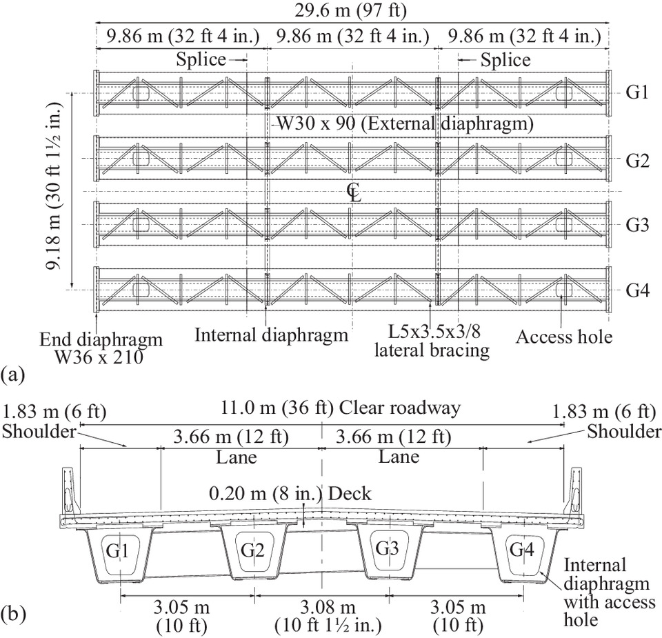
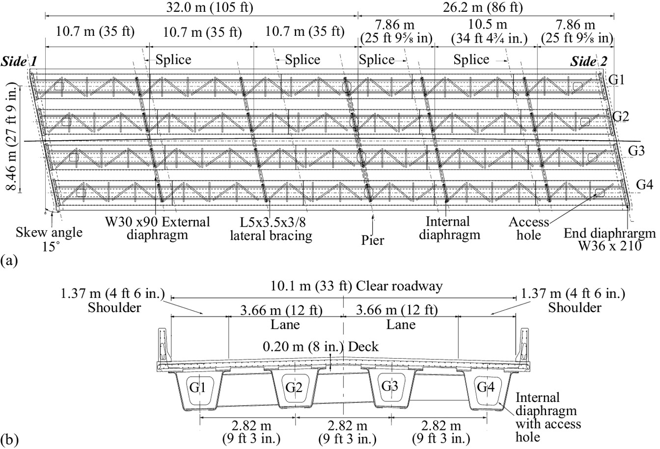
The objectives of this paper are to: (1) introduce the built-up PBTG system; (2) numerically demonstrate its feasibility through FE numerical modeling; and (3) investigate internal redundancy by evaluating behavior when a steel component is abruptly lost. The focus is on the behavior of two demonstration bridges that will be built in Indiana in 2023: a simple span bridge [29.6-m (97-ft) span] and a two-span continuous bridge [32.0-m (105-ft) and 26.2-m (86-ft) spans]. The paper will provide the cross sections for these bridges, as well as design details such as lateral bracing, diaphragms, and abutments. High-fidelity, three-dimensional (3D) FE numerical models are used to demonstrate the behavior under dead and live load, as well to evaluate stability during construction. Finally, internal redundancy is investigated by considering the behavior when a flange or web is fractured. This paper focuses on the overall design decisions and demonstrates the behavior of these bridges through high-fidelity FE analyses. All bridge components were designed to meet current American Association of State Highway and Transportation Officials (AASHTO) Load and Factor Resistance Design (LRFD) Bridge Design Specifications (AASHTO 2020), but the details of each provision are not shown for conciseness.
Built-Up Press Brake-Formed Tub Girders
Fig. 1 depicts the general cross section for built-up PBTGs, with specific dimensions also provided for the two demonstration bridges. Figs. 2 and 3 provide the plan and section for the two demonstration bridges. The two built-up PTBG demonstration bridges were designed to meet all requirements of current AASHTO LRFD Bridge Design Specifications (AASHTO 2020).
To simplify and accelerate fabrication, the steel thicknesses/section sizes and material properties were specifically chosen based on: (1) availability of steel from manufacturers; (2) using the same thicknesses/section sizes for as many components of the bridge as possible; and (3) using the same thicknesses/section sizes among the two demonstration bridges. The first criterion aims to eliminate or reduce any supply chain issues in acquiring the necessary components. The latter two criteria are promoting the aforementioned “kit-of-parts” approach. The aim was not to minimize material, but to optimize fabrication.
More specifically, in the development of the built-up PBTG system, a goal has been to adapt workflows associated with transmission pole manufacturing to substantially reduce bridge fabrication times. Transmission pole manufacturers routinely bend plates (via a press brake) with thicknesses up to 19.1 mm (0.75 in.) that are subsequently seam-welded to produce a tapered monotube structure system. Traditional bridge fabrication workflows require preparation of shop drawings before steel can be ordered. Mill orders typically take 8 to 10 weeks for steel delivery adding substantial time before steel fabrication can begin. For pole manufacturers, large quantities of mill plate are in stock at the manufacturing facility, such that fabrication of built-up PBTGs can proceed immediately, provided the stock plate used in transmission poles will meet or exceed the requirements for bridge steel. In addition, bend radii for transmission poles are standardized against dies that are used in the press brake. These considerations were foundational to the choices of the cross section and the material properties, as outlined in the following subsections.
Cross Section
The components of the cross section were kept the same among the two bridges, with the exception of the top and bottom flange thicknesses in the negative moment region of the two-span continuous bridge (Fig. 1).
The component thicknesses were selected from steel that is typically stockpiled. As this research aims to harness of the capabilities of the adjacent transmission pole manufacturing industry, plate thicknesses were chosen to align with the steel that is stockpiled by these manufacturers. Specifically, transmission pole manufacturers stock plates in 1.59-mm (0.0625-in.) increments for plates less than 19.1 mm (0.75 in.) thick. Plates greater than 25.4 mm (1 in.) thick are typically stocked in 6.35-mm (0.25-in.) increments.
For the simply supported span and the positive moment region of the two-span continuous bridge, the top flanges have a thickness ttf = 25.4 mm (1 in.) and a width wtf = 457 mm (18 in.), and the bottom flanges have a thickness tbf = 25.4 mm (1 in.) and a width wbf = 864 mm (34 in.). In the negative moment region of the two-span continuous bridge, the thicknesses of the top flange and bottom flange are increased to ttf = tbf = 38.1 mm (1.5 in.). Note that the strategy of thickening the bottom flange in the negative moment region was to: (1) avoid needing stiffeners to prevent plate buckling and (2) maintain a kit-of-parts where the flanges are cut from just two different plate thicknesses. The webs of both bridges have a thickness tw = 15.9 mm (0.625 in.).
To facilitate internal inspection (see forthcoming discussion), the overall girder depth was maximized while taking into account high water elevations (both demonstration bridges are above water). This led to a web depth d = 0.981 m (38.625 in.). The 1 to 4 web inclination was selected in accordance with current AASHTO LRFD Bridge Design Specifications (AASHTO 2020).
The bend radius (to be discussed further later) at the top (rt) and at the bottom (rb) of the web are both 55.6 mm (2.1875 in.). At the top of the web, an overhang wtw = 178 mm (7 in.) is provided for connectivity to the top flange by staggered bolts and to facilitate fabrication of the bend. Likewise, at the bottom of the web, an overhang wbw = 152 mm (6 in.) is provided for the single line of bolts and for fabrication.
The cross section is composite with a reinforced concrete deck with a thickness td = 203 mm (8 in.). Shear studs [22.2-mm (0.875-in.) diameter; spaced every 0.305 m (12 in.) longitudinally; three shear studs per row], not depicted in Fig. 1, are used to achieve this composite behavior.
The cross section for each demonstration bridge met the current AASHTO LRFD Bridge Design Specifications (AASHTO 2020) requirements for shear, moment, torsion, and so forth.
Camber is achieved by using piecewise straight components that are kinked at the splices.
Material Properties
Yield Strength
For plates less than 19.1 mm (0.75 in.) thick, transmission pole manufacturers stock material with a specified yield strength of 448 MPa (65 ksi), either ASTM A572 (ASTM 2021a) for hot-dip galvanized applications or ASTM A871 (ASTM 2020) for weathering steel applications. This stock is what is cold bent in their manufacturing processes. As the owner had a preference for hot-dip galvanizing as the corrosion protection system, the cold bent webs for the demonstration bridges are ASTM A572 (ASTM 2021a) Grade 65 [i.e., 448-MPa (65-ksi) specified yield strength] steel.
Plates greater than 25.4 mm (1 in.) in thickness are typically not cold bent by transmission pole manufacturers, but are used for example as base plates. These plates typically have a yield strength of 345 MPa (50 ksi). Thus, for the demonstration bridges in this project, the flanges are designed as ASTM A572 (ASTM 2021a) Grade 50 [i.e., 345-MPa (50-ksi) specified yield strength] steel.
For these reasons, this research is using a hybrid cross section with 448-MPa (65-ksi) webs and 345-MPa (50-ksi) flanges.
Impact Energy
Ensuring that bridge steels have adequate fracture toughness is a key aspect of durability. AASHTO LRFD Bridge Design Specifications’ fracture toughness requirements [which are framed as minimum Charpy V-Notch (CVN) impact energy requirements] for bridge steels were developed in the early 1970s (Barsom 1975), partly in response to the Point Pleasant bridge collapse in 1967. As outlined by Barsom (1975), the purpose of fracture toughness requirements in bridge steels is to prevent unstable crack propagation, noting that “most of the useful life of a component is expended by initiating and propagating cracks at modest stress levels,” such that fracture toughness may have a “negligible effect on the useful life of a structural component.” However, bridges that have incorporated low toughness steel prior to the advent of these design requirements have, on occasion, failed dramatically with unstable crack propagation. With the advent of minimum CVN impact energy requirements and fatigue resistant design (particularly provisions for distortion induced fatigue), brittle fractures and fatigue cracks in bridges built after 1985 are rare (Connor and Lloyd 2017).
As outlined by Barsom (1975), fracture toughness is influenced by three key parameters—plate thickness, service temperature, and loading rate, with a reduction in toughness associated with thicker plate, lower temperature, and higher loading rate. Barsom (1975) demonstrated clear correlation between CVN impact energy and steel fracture toughness, with later research providing alternative correlations. The reader is referred to Collins et al. (2016) for a thorough review of these correlations. For the last nearly 50 years and into the foreseeable future, material requirements for steel used in bridges (i.e., ASTM A709 ASTM 2021b) will include minimum CVN requirements as an easily measured quantity that is correlated with fracture toughness, based upon thickness and minimum service temperature.
It should also be noted that minimum CVN requirements per AASHTO LRFD Bridge Design Specifications are based upon plates in the as-rolled condition. There is no direct assessment of the change in fracture toughness associated with forming bridge steels. Instead, current AASHTO LRFD Bridge Construction Specifications limit cold bending to a minimum radius of 5t, where t is the thickness. Smaller radii are also acceptable if approved by the engineer. These limits are intended to prevent the cold bending process from significantly reducing the fracture toughness and ductility of the steel (AASHTO 2017, 2020). It is based on the research of Keating and Christian (2012) that found that strains from cold bending that exceed 10 percent (which corresponds to the 5t bend radius) reduce ductility and fracture toughness, with fracture toughness being evaluated by the empirically correlated CVN impact energy. See Gerbo et al. (2016) for further discussion.
In contrast, the European design code (CEN 2005) accounts for the effect of cold bending on fracture toughness by using a temperature-shift approach to CVN requirements, which has been validated through research on North American steels (Sun and Packer 2014; Sun 2014). Significant work on bend radius and its influence on toughness has been conducted on hollow structural sections (HSSs), where steel subjected to cold bending in the corners can be compared directly with steel in the flat portion that has not been cold worked. Results have demonstrated that the degree of cold working can be used as a measure to identify loss in toughness that comes in the form of a temperature shift for CVN requirements, which results in both an upper shelf reduction as well as a lateral shift in temperature.
The temperature shift, ΔT, recommended by European code to account for cold forming of steel is calculated as , where is the degree of cold forming in percent (CEN 2005). This degree of cold forming for steel with an elongation at yield of two percent is:where r = the bend radius (Sedlacek et al. 2008; Sun 2014).
(1)
The proposed bend radii for this project is 3.5t, which while consistent with the dies used in pole manufacturing does not meet the 5t minimum of current AASHTO LRFD Bridge Construction Specifications. Thus, further investigation has been conducted using the temperature-shift approach to CVN requirements per the European design code (CEN 2005).
As noted earlier, transmission pole manufacturers stock steel that is intended to be bent [i.e., plates less than 19.1 mm (0.75 in.) thick] as ASTM A871 (ASTM 2020) Grade 65 or ASTM A572 (ASTM 2021a) Grade 65. ASTM A871 (ASTM 2020) Grade 65 steel has significantly more stringent CVN requirements [20 J at (15 ft-lbf at )] than does current AASHTO LRFD Bridge Design Specifications, which require a minimum of 20 J at (15 ft-lbf at ) for nonfracture critical bridge steels or 34 J at (25 ft-lbf at ) for fracture critical bridge steels (for Zone 2) (ASTM 2021b; AASHTO 2020). If ASTM A572 (ASTM 2021a) Grade 65 steel is used in pole manufacturing, it is subject to a supplemental requirement for minimum CVN of 20 J at (15 ft-lbf at ). It is also required to be manufactured to fine grained practice and have low carbon equivalencies (less than 0.47). These requirements used in pole manufacturing therefore exceed AASHTO LRFD Bridge Design Specifications requirements for CVN impact energy, and are therefore appropriate for use in bridges.
For the 15.9-mm (0.625-in.)-thick web steel bent to a radius of 3.5t in this research, ( ). Applying this temperature shift for the proposed steel with CVNs of 20 J at (15 ft-lbf at ) still meets the AASHTO LRFD Bridge Design Specifications requirement of 20 J at (15 ft-lbf at ), that is, ( ). Note that as the demonstration bridges are load path redundant, comparisons are made considering the minimum CVN requirement of 20 J at (15 ft-lbf at ). Analogous calculations could be made with other minimum requirements as needed. In comparison, current AASHTO LRFD Bridge Construction Specifications allow bending to 5t, which would correspond to a “permissible” temperature shift of ( ) and an effective CVN after bending of 20 J at (15 ft-lbf at ).
Prior to fabrication of any tub girder components, material certifications for the proposed material must be provided and approved by the engineer. Steel used in transmission pole manufacturing is routinely specified to have minimum CVN requirements of 20 J at (15 ft-lbf at ) and material certifications for the demonstration bridges in this project far exceed this minimum. This suggests that pole manufacturing steels are well suited to cold working and are good candidates for built-up PBTGs.
Abutments, Diaphragms, and Lateral Bracing
Integral abutments are used for both bridges. To maintain a kit-of-parts comprising readily available stockpiled steel, the cold bent webs of the tub girders are bolted to standard rolled wide flange sections (W 36 × 210) via angle sections (L 5 × 3.5 × 3/8), forming the end diaphragms. The wide flange sections are supported by an end bent bearing assembly that includes shims, steel plate, and an S section (S3 × 7.5 × 1). These abutments are encased in reinforced concrete. At the pier of the two-span continuous bridge, elastomeric bearing pads are used.
At approximately third points of each span (Figs. 2 and 3), 15.9-mm (5/8-in.)-thick plate internal diaphragms are used as secondary members with the purpose of shape-holding, with access holes as discussed in the following section. The thicknesses and grade (i.e., ASTM A572 ASTM 2021a Grade 65) of these internal diaphragms were selected to match those of the webs, with the aim of using the least number of different steel plates as possible for fabrication efficiencies. At the pier of the two-span continuous bridge, the thickness of the internal diaphragm is increased to 25.4 mm (1 in.) due to the increased shear demand at that location. This plate thickness aligns with the thickness of the flanges, in keeping with the mindset of using the same steel thicknesses throughout. The internal diaphragms are connected to the web and bottom flange by L 5 × 3.5 × 3/8 sections (or equivalent bent plates to accommodate the skew of the two-span continuous bridge) via bolts.
W 30 × 90 wide flange sections are used as exterior diaphragms, connected to the webs by L 5 × 3.5 × 3/8 angle sections. As the two-span continuous bridge has a skew angle of 15°, bent plates with the same dimensions as the angle sections are used to connect the webs to the abutments and diaphragms. Lateral bracing (L 5 × 3.5 × 3/8 angle sections) is used to connect the top flanges.
In these design decisions, the focus was on using the same of each type of component repeatedly (e.g., all angles are L 5 × 3.5 × 3/8 sections). While this approach may be heavy on steel, it has the potential to lead to cost savings and is in line with a “kit-of-parts” approach, where a fabricator only needs to stockpile a limited number of different sections.
Inspection Access
A key consideration in the design of trapezoidal girders in steel or concrete is inspection access. Short-span prestressed concrete tub/U girders and prestressed concrete box girders traditionally do not provide internal inspection access. Steel box girders, with the exception of the U-shaped ribs of orthotropic decks, typically provide internal access for web to flange and diaphragm weld inspection.
As the built-up PBTGs do not use welded construction, there is much less need for internal maintenance and inspection. All connections of the primary members will be on the exterior. In addition, the redundancy measures further reduce the need for routine internal inspection and maintenance. However, it is best practice to provide adequate internal access.
A challenge with providing inspection and maintenance access to short-span tub girders is depth and the resulting bottom flange width. The proposed cross sections have internal depths of less than 1.02 m (40 in.) and clear bottom flange widths of 0.610 m (24 in.). The Indiana Department of Transportation (INDOT) design manual recommends a minimum opening of 0.457-m (18-in.) wide by 0.914-m (36-in.) deep in a pier diaphragm and a minimum 0.762-m (30-in.) diameter access door in the bottom flange at the girder ends (INDOT 2017). As the lateral bracing reduces the head room to less than 0.914 m (36 in.) and there is limited width of the bottom flange, following the INDOT recommended minimum opening becomes impractical. For these shallow depth tub girders, an evaluation of minimum inspection access requirements from the dual perspective of accessibility and emergency egress has been performed.
There are no specific Occupational Safety and Health Administration (OSHA) or AASHTO minimum requirements for inspection access to bridge box girders, although many State Departments of Transportation provide guidance or standards for openings. There are explicit minimum opening requirements for residential construction as a means of emergency egress and rescue both in the International Building Code (IBC 2018) and International Residential Code (IRC 2018). These requirements are 0.610-m (24-in.) height and 0.508-m (20-in.) width, and a total opening cross sectional area of no less than 0.465 m2 (5.0 ft2) for grade openings. Note that this exceeds INDOT standards in terms of cross sectional area and minimum width.
For built-up PBTGs, it is therefore recommended that internal access be provided, that these minimum IBC/IRC requirements be met, and that the opening size be maximized to the extent practical. For the demonstration bridges, the access holes in the flanges are 0.610-m (24-in.) wide transversely and 0.914-m (36-in.) long longitudinally. The internal diaphragms feature access openings that are 0.610-m (24-in.) wide at the base, 0.965-m (38-in.) wide at the top, and have a height of 0.711 m (28 in.). A 0.152-m (6-in.) radius is used for all corners. See Figs. 2 and 3.
Other Details
As the cold bent webs will be fabricated via a press brake, the length of the steel components are limited by available press brakes and tooling (related to both physical length of the brake and tonnage available). The fabricator should be consulted prior to design to determine maximum lengths and thicknesses for the webs. For the fabricator used in this research, the maximum length for the web parts used is 13.7 m (45 ft). Bolted splices are used at these intervals to connect the components. This also enables kinks to achieve camber. Importantly, lengths of components would be limited, making them transportable by truck without a special permit. It is envisioned that the entire cross section could be bolted up on site or a fabricator could bolt-up the cross section in a shop and then only make bolted field splices between segments.
Corrosion protection that is compatible with built-up PBTGs includes hot-dip galvanizing, metallizing, conventional multicoat paint, or the use of weathering steel. As discussed earlier, galvanizing will be used for these demonstration bridges based on the prior success of galvanized projects in Indiana.
Feasible Span Lengths
Simple spans up to 82.3 m (270 ft) or continuous spans up to 96.0 m (315 ft) are feasible with built-up PBTGs. Typical steel slab from the mill comes in widths between 3.05 m (120 in.) and 3.66 m (144 in.), with new mills providing slabs up to 4.32 m (170 in.) in width. Therefore, a maximum web depth would be approximately 2.74 m (9 ft) [or 3.05 m (10 ft) with new mill capabilities], assuming at least some steel is needed for the flat top and bottom portions of the web. Assuming a span to depth ratio of 30 for a simple span and 35 for a continuous span (AASHTO 2020), this leads to the aforementioned span limits. A lower bound on span length would be approximately 18.3 m (60 ft) as existing PBTGs that are fabricated from a single plate are competitive below this range. For deeper girders, the web thickness could be increased to 19.1 mm (0.75 in), which is still stockpiled by transmission pole manufacturers for bending and would satisfy the AASHTO LRFD Bridge Design Specifications proportion limits for webs without longitudinal stiffeners. Web buckling did not govern the design of the demonstration bridges in this paper, but this would need to be evaluated and all slenderness limits would apply. Stiffeners could also be added as needed.
Finite-Element Numerical Modeling
The behavior of the demonstration bridges was evaluated using 3D FE models in ABAQUS (ABAQUS 2022). Note that the focus of this paper is to demonstrate the behavior of these bridges through these high-fidelity FE analyses. Design-level analyses were also performed that confirmed that all bridge components meet current AASHTO LRFD Bridge Design Specifications.
All steel components and the reinforced concrete deck are modeled using S4R or S3R shell elements (four or three node reduced integration elements with six degrees of freedom per node). Based on a mesh refinement study, a mesh size of 25.4 mm (1 in.) is used for steel components and 101.6 mm (4 in.) is used for the concrete deck. Linear geometry is assumed.
An elastic, perfectly plastic stress–strain relationship is used for the steel, with the appropriate yield strength for each component. The modulus of elasticity is assumed to be 200 GPa (29,000 ksi), the density is assumed to be 7,850 kg/m3 (490 lb/ft3), and Poisson’s ratio is assumed to be 0.3. A linear concrete material model is used for the 28 MPa (4 ksi) compressive strength concrete deck, with an elastic modulus of 27,234 MPa (3,950 ksi) (based on Equation C5.4.2.4-1 of AASHTO 2020). A density of 2,403 kg/m3 (150 lb/ft3) and a Poisson’s ratio of 0.2 is assumed. When considering negative moment behavior (i.e., when the deck would be in tension), the contribution of the deck is not included. This is handled numerically by making the stiffness of the concrete material model negligibly small.
Bolted connections are modeled by connecting the relevant surfaces through surface-to-surface or node-to-surface tie constraints, which constrain all degrees of freedom. Composite behavior between the reinforced concrete deck and the top flange flanges of the girders is enforced through surface-to-surface constraints.
For the simple span bridge, vertical and longitudinal translation is restrained at the end diaphragm on one side and vertical translation is restrained on the other. Transverse restraint for stability is provided at both end diaphragms of one girder line. For the two-span continuous bridge, vertical, transverse, and longitudinal translation is restrained at the end diaphragm on one side and vertical and transverse translation is restrained at the other end diaphragm. At each end diaphragm, these boundary conditions are applied at two nodes representing the centroid of each of the two bearing assemblies. These nodes are designated as “leader” nodes, and additional nodes [152 mm (6 in.)] in the transverse direction “follow” these nodes to represent the width of the bearing assemblies. At the pier of the two-span continuous bridge, translation is restrained in the vertical and transverse directions, applied at single nodes in the middle of the flat, bottom web region.
The behavior of the bridges under dead and live load is evaluated through static analyses. For the analyses shown in this paper, live load includes a design lane load of 9.34 kN/m (0.64 k/ft) and a design truck [loads of 35.5 kN (8 k), 142 kN (32 k), and 142 kN (32 k), spaced at 4.27 m (14 ft) and a variable spacing of 4.27–9.14 m (14–30 ft), respectively] placed for worst effect. Note that the demonstration bridges were designed considering either a design truck or a design tandem, in accordance with current AASHTO LRFD Bridge Design Specifications live loads. As the design truck governed for the simple span bridge and the positive moment region of the two-span continuous bridge, data presented in this paper only show the design truck loading. For the negative moment region of the two-span continuous bridge, 90% of the load of two design trucks were used with the spacing as specified in the current AASHTO LRFD Bridge Design Specifications. A dynamic impact factor of 33% is applied to the design truck. As three vehicular lanes could be placed on the simple span bridge, three lanes of live load are considered (no multiple presence factor is applied in the data shown in this paper). For the two-span continuous bridge, only two lanes are considered.
Fatigue stress ranges are evaluated under live load of a single design truck (Fatigue I in AASHTO 2020). A live load factor of 1.75 and a dynamic impact factor of 15% are applied. The rear axles of the truck are spaced at 9.14 m (30 ft).
To evaluate stability during construction, linear eigenvalue analyses are conducted. The focus is on the behavior during the most critical time of construction, that is, when the girders have been erected and the concrete deck has been poured but not yet hardened. The girders, abutments, and lateral bracing, as well as the interior and exterior diaphragms, are modeled. However, the deck is not included in the model. A superimposed load representing the deck is applied to the top flanges of the tub girders. Loads include the steel self-weight and this superimposed load of the deck.
The methods used for investigating redundancy will be discussed in that section.
Behavior of Demonstration Bridges
Simple Span Bridge
Fig. 4 depicts the the von Mises stresses under dead and live load (without load factors) for the simple span bridge. At midspan, the peak stresses in the bottom flange and web region are low. The peak von Mises stress is located in the flat bottom portion of the web with a magnitude of 125 MPa (18.1 ksi), which is only 27.8% of its yield strength [Fig. 4(a)]. If a Strength I load combination (with a load factor of 1.25 for dead load and 1.75 for live load as per AASHTO 2020) is evaluated, the stress increases to 190 MPa (27.5 ksi), which is 42.3% of the web’s yield strength. Figs. 4(b–d) also depicts the detailed stresses at the interior diaphragm, at the web and end diaphgram connection, and around the bottom flange access hole. While there are stress increases in these regions, they are still low compared with the yield strength.
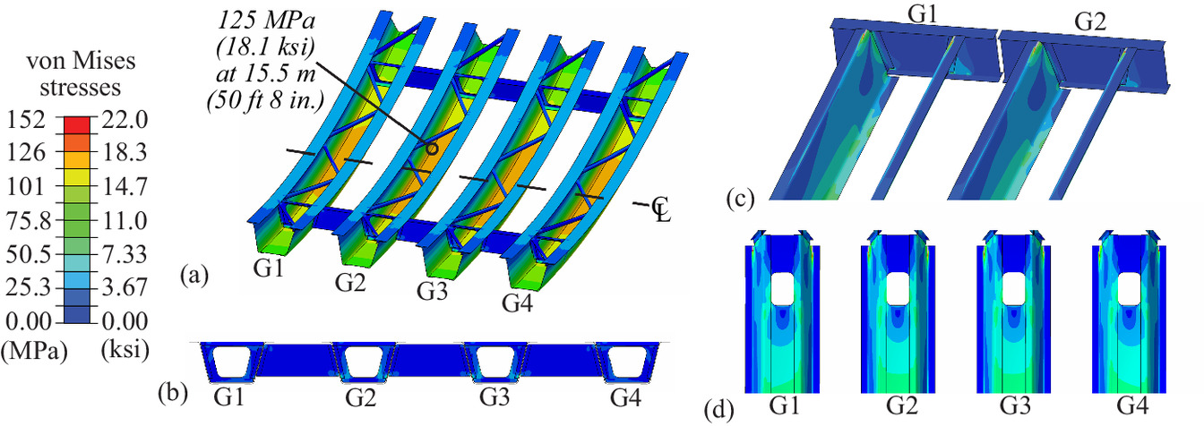
Considering the fatigue limit state, the longitudinal stress range of the bottom flange to web connection of the girders under the load of the design truck is 25.4 MPa (3.68 ksi) which is far below the nominal fatigue resistance of 110 MPa (16 ksi) for Category B details (AASHTO 2020). This further demonstrates the robustness of the system as well as its increased durability and lifespan as it is less prone to fatigue-induced cracks.
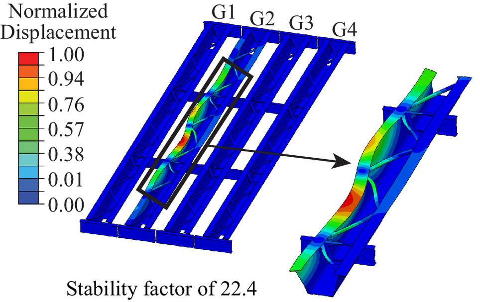
Fig. 5 depicts the buckling mode for the simple span bridge under construction loads. As expected, for the lowest positive mode, the top flange of a girder line would locally buckle, with restraint provided by the lateral bracing. This local mode of buckling is preferred over a more global mode. The stability factor is very high (22.4), demonstrating safety during construction.
Two-Span Continuous Bridge
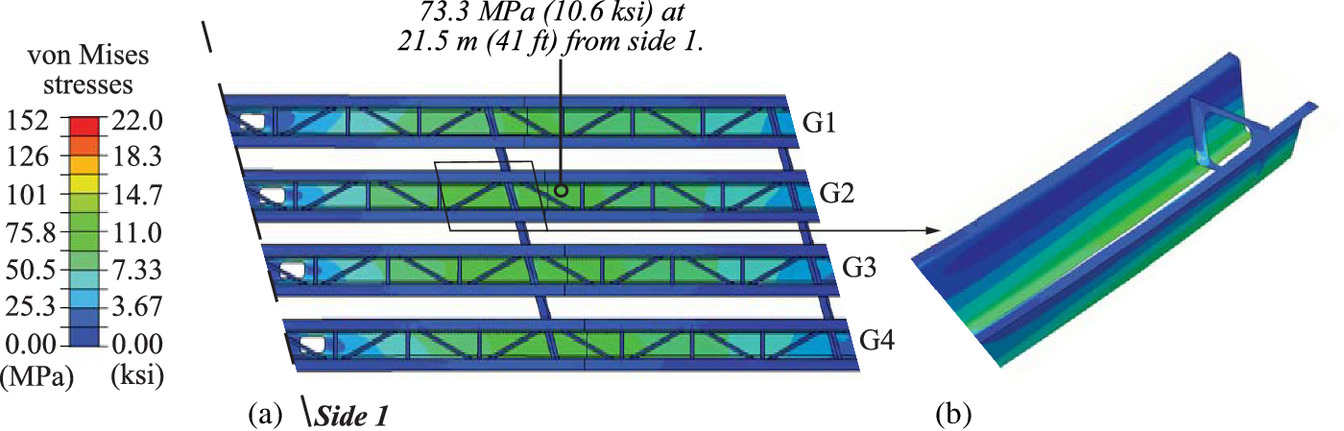
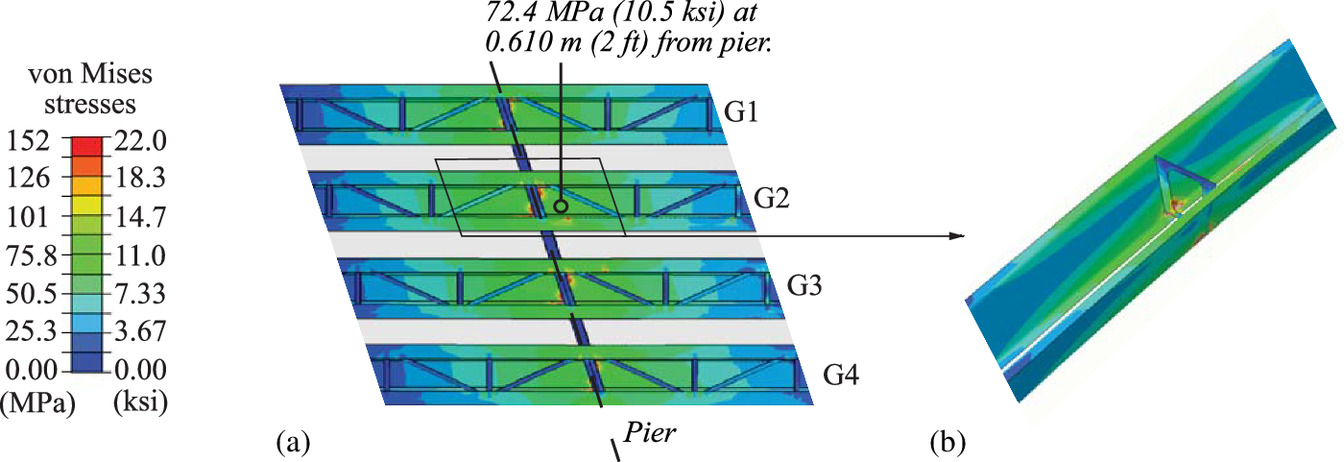
Figs. 6 and 7 depict the behavior of the two-span continuous bridge under dead and live load (without load factors) when the live load is positioned for peak positive moment and peak negative moment, respectively. The peak stresses for the positive moment scenario occur in the longer of the two spans near the location of the first set of diaphragms. The peak von Mises stress occurs in the flat bottom portion of the web at a location of 21.5 m (41 ft) from the end bent with a magnitude of 73.3 MPa (10.6 ksi) (Fig. 6). For the negative moment scenario, the peak von Mises stress occurs just above the pier, as expected. At 0.61 m (2 ft) from the pier, the peak von Mises stress in the flat bottom portion of the web is 72.4 MPa (10.5 ksi). Note that this value is taken 0.610 m (2 ft) away from the pier as localized effects from the point boundary condition result in unrealistic stress concentrations. These are all far below (less than 17% of) the 448 MPa (65 ksi) specified yield strength of the webs, demonstrating the conservative design. Considering a Strength I load combination, the positive moment von Mises stress increases to 107 MPa (15.5 ksi) and the negative moment increases to 108 MPa (15.7 ksi), which is 23.8% and 24.1%, respectively, of the yield strength.
The fatigue longitudinal stress range considering positive moment is 19.4 MPa (2.81 ksi) at the bottom flange to web connection. Considering negative moment, the longitudinal stress range is 11.4 MPa (1.65 ksi) at the top flange. Both cases are far less than the 110-MPa (16-ksi) Category B nominal fatigue resistance for bolted connections. In the negative moment region, shear studs may control the fatigue category [i.e., Category C with a nominal fatigue resistance of 68.9 MPa (10 ksi)]. The fatigue stress range for the steel section still meets the criteria for Category C.
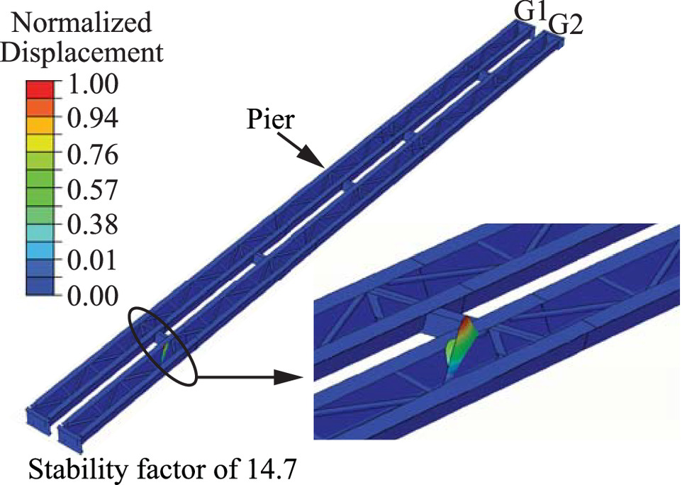
The two span bridge will be built using a phased construction approach, with two girder lines and the deck constructed first to facilitate traffic while the other two girder lines are being built. Stability during construction was thus evaluated considering just two girder lines supporting the dead load of wet concrete. As depicted in Fig. 8, a high stability factor of 14.7 was found and the buckling mode is a preferred local mode of lateral brace buckling.
Evaluation of Internal Redundancy
One of the aims of using a built-up section is to make a primary member that is fully or partially in tension an internally redundant member, meaning that fracture of one component of the cross section (e.g., a web or a flange plate) would not propagate through the member (FHWA 2015a; Connor et al. 2023; FHWA 2022; NBIS 2022). This enhances the overall resiliency of the system. From an owner’s perspective, this internal redundancy would mean that the member is not a nonredundant steel tension member (NSTM), and would therefore not be subject to the hands-on inspection requirements of NSTMs (FHWA 2022; NBIS 2022).
The two demonstration bridges in this project are load path redundant based on the number and spacing of the primary load-carrying members (FHWA 2015a; Connor et al. 2023; FHWA 2022; NBIS 2022). As a result, regardless of their internal redundancy, the steel girders would not be subject to the hands-on inspection requirements of NSTMs (FHWA 2022; NBIS 2022). Although there would be no additional inspection benefits, internal redundancy still offers enhanced resistance to fracture, thereby contributing to an overall more resilient structural system. Further, built-up PBTGs could be used in a two-girder configuration, which would not be load path redundant. In that scenario, being internally redundant would exempt the girders from the NSTM inspection requirements.
This paper investigates the internal redundancy of the simple span bridge when subjected to sudden loss of either a bottom flange or a web in an interior girder line (i.e., Girder G2). Three behaviors are considered: (1) instantaneous dynamic behavior (of the order of milliseconds) including the effect of the high-velocity stress wave; (2) short-term dynamic behavior (of the order of seconds) focusing on the load redistribution; and (3) long-term static behavior of the faulted structure. These behaviors are evaluated using a high-fidelity 3D FE model developed in ABAQUS (ABAQUS 2022).
A review of numerical techniques to evaluate bridge redundancy is provided by Tumbeva et al. (2022). Most notably, AASHTO recently published Guide Specifications for Analysis and Identification of Fracture Critical Members and System Redundant Members (AASHTO 2018) based on the findings of National Cooperative Highway Research Program (NCHRP) Report 883 Fracture-Critical System Analysis for Steel Bridges (Connor et al. 2018). This guide specification identifies two load combinations for evaluating redundancy:where DC = the dead load of structural/nonstructural components, DW = the dead load of the wearing surface and utilities, LL = the vehicular live load, and IM = the vehicular dynamic load allowance (IM = 0 for Redundancy I and IM = 0.15 for Redundancy II). No wearing surface is considered in this research. DAR is a dynamic amplification factor to be applied when a user does not perform a dynamic analysis. As this research is performing a dynamic analysis, DAR = 1. In this research, Redundancy I is used to evaluate the instantaneous and short-term dynamic behaviors, and Redundancy II is used to evaluate the long-term behavior of the faulted structure.
(2)
(3)
The 3D FE models discussed previously are used for this investigation, with some modifications. Specifically, the redundancy evaluation requires an explicit dynamic analysis to capture both the instantaneous and short-term behaviors, as well as a nonlinear static analysis to demonstrate long-term performance. Nonlinear geometry is incorporated as component loss is likely to cause large deflections. Additionally, a nonlinear steel material model including linear strain hardening (with peak strain at failure of 0.05) is used to understand stress redistribution after component failure (as recommended by AASHTO 2018). The ultimate strength for the cold bent webs is 552 MPa (80 ksi) and for the other steel components, it is 483 MPa (70 ksi).
Instantaneous Dynamic Response
This paper uses the approach presented by Tumbeva et al. (2022) to simulate the instantaneous dynamic response following the fracture of a web or flange of one girder line. The method is also briefly outlined in this section. A static analysis of the bridge is performed first, using the Redundancy I load combination, to establish the initial (undamaged) stress state of the bridge. This initial stress state is then incorporated into a separate model, in which 25.4 mm (1 in.) along the length of the web (over its full depth) or 25.4 mm (1 in.) along the length of the flange (over its full width) are removed. A force of equal magnitude and opposite direction to the force acting on the removed elements prior to damage is applied at the failure surfaces. An explicit dynamic analysis is carried out in which the force is instantaneously released in 0.0005 ms and the structure is allowed to vibrate freely. The rate of load release was established through a parametric study by Tumbeva et al. (2022). As a result, a high-velocity stress wave propagates rapidly [e.g., 5,189 m/s (17,024 ft/s for steel)] which in turn causes dynamic strain rates to be developed in the section’s components.
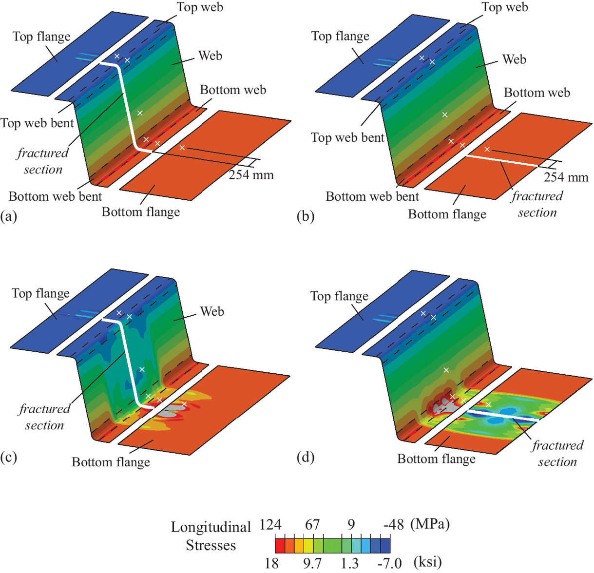
Fig. 9 depicts the longitudinal stress contours when a web or flange is fractured in an interior girder line at midspan, including the initial, undamaged stress profile [Figs. 9(a and b)] and the stress profile as the high-velocity stress wave propagates [Figs. 9(c and d)]. In both cases, the change in stress is primarily in the damaged component, with some additional local stress concentrations in the adjacent component. Importantly, the stresses are below yield, further demonstrating the high level of internal redundancy of the system.
Figs. 10(a and c) depict the longitudinal stress at specific locations (marked with an x in Fig. 9) as a function of time, for the case when a web or bottom flange fractures, respectively. The large stress drop at approximately 0.06 ms corresponds to the passage of the high-velocity stress wave. In both cases, there is little change in stress of the top web or top web bent regions, likely due to the restraint provided by the deck. Larger changes in stress are observed in the web, bottom web bent, and the bottom web region, as well as the bottom flange. This behavior is expected at these locations, as the tensile stresses are the highest, and therefore the impact of the high-velocity stress wave is more distinctly defined. However, the relatively small change in tensile stress at the bottom flange, when the web is fractured, indicates that a fracture of the web does not propagate into the bottom flange, allowing the section to remain relatively intact. Similar behavior is observed when the bottom flange is fractured, with small changes in stress occurring in the web locations. The time history diagrams, as well as the stress contours, clearly demonstrate that fracture of one component does not have an impact on the adjacent components and the section is not further compromised.
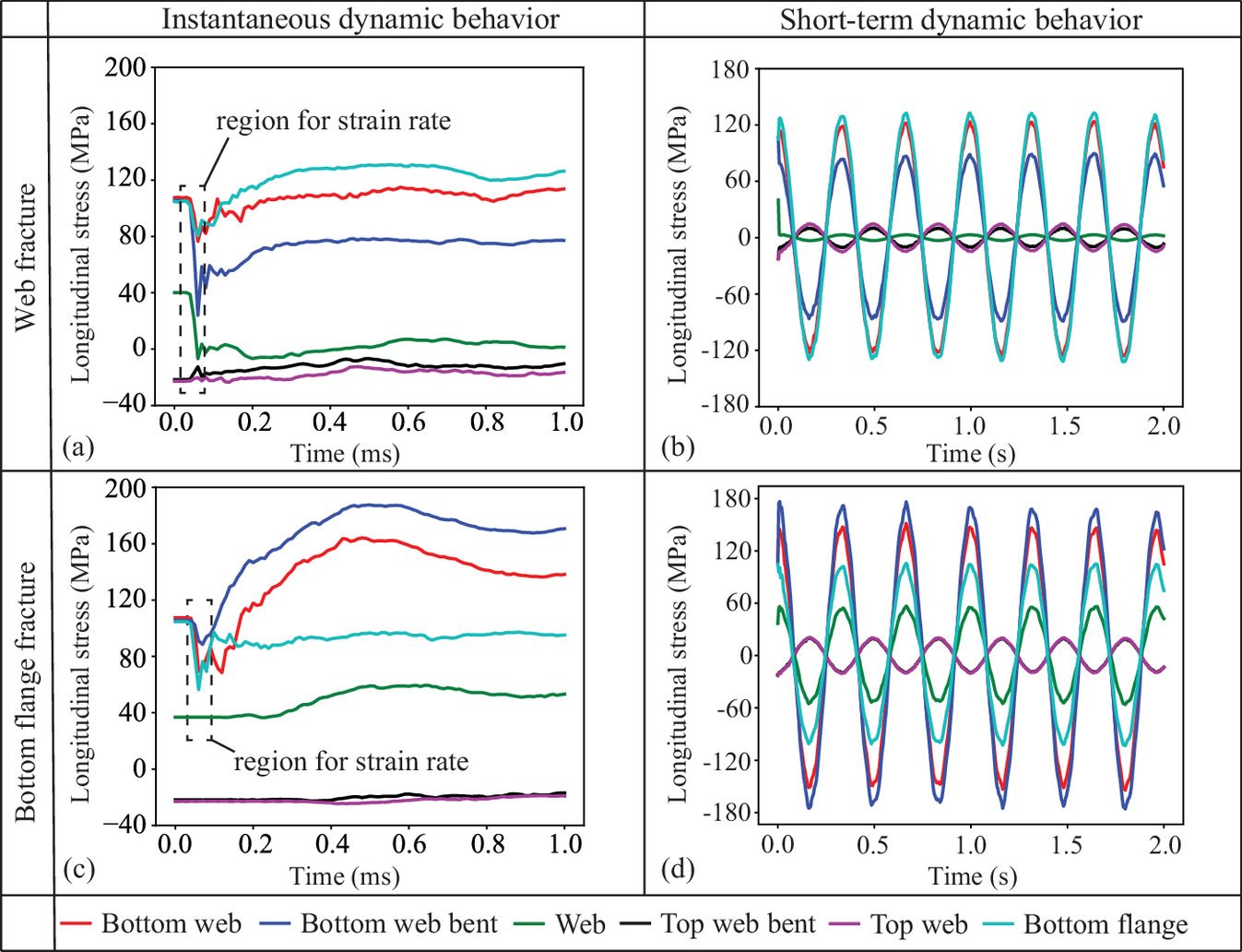
During this passage of the high-velocity stress wave, strain rates (Table 1) are predominantly in the dynamic region (of the order of 10/s). This dynamic loading is associated with a reduced fracture toughness of the material (Barsom 1975), where fracture toughness was correlated with the CVN impact energy. The peak strain rates are recorded in the web locations and bottom flange for both fracture cases, as expected. Importantly, the bottom web bent, which is also the most critical location, experiences the highest strain rates of 19.6/s. For reference, typical bridge steel is subjected to intermediate loading rates from live load, with strain rates of the order of less than 10−3/s (Barsom 1975). These dynamic strain rates developed as a result of the web or flange fracture combined with the cold bending, further emphasize the importance of evaluating the fracture toughness of the steels to be used.
| Strain rate (/s) | |||||||
|---|---|---|---|---|---|---|---|
| Behavior | Fracture scenario | Bottom web | Bottom web bent | Web | Top web bent | Top web | Bottom flange |
| Instantaneous | Web | 7.51 | 19.6 | 8.02 | 2.20 | 0.613 | 5.39 |
| Bottom flange | 9.43 | 2.82 | 0.402 | 6.37 × 10⁻² | 2.5 × 10⁻³ | 11.6 | |
| Short term | Web | 7.89 × 10⁻³ | 5.34 × 10⁻³ | 6.66 × 10⁻⁴ | 1.81 × 10⁻⁴ | 8.59 × 10⁻⁴ | 8.58 × 10⁻³ |
| Bottom flange | 9.52 × 10⁻³ | 1.13 × 10⁻² | 3.55 × 10⁻³ | 1.28 × 10⁻³ | 1.34 × 10⁻³ | 6.16 × 10⁻³ | |
Short-Term Dynamic Response
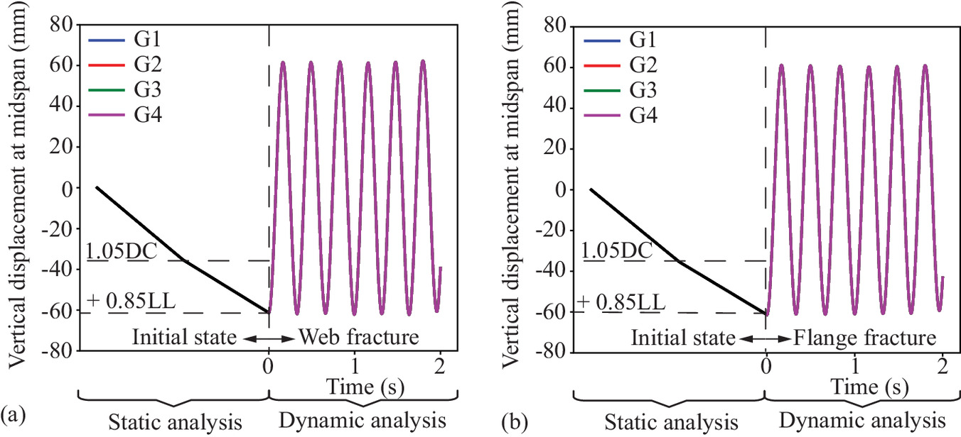
This section investigates the short-term dynamic response of the system when the web or flange is lost, with a focus on behavior on the timescale of seconds, as opposed to the instantaneous behavior which focused on the effect of the high-velocity stress wave on a timescale of milliseconds. Damping was conservatively not included. Fig. 11 depicts the global short-term dynamic response, represented by the vertical displacement at midspan as a function of time for all four girder lines (the fracture occurs only in Girder G2). In both the case of the web fracture and the flange fracture, all four girder lines oscillate together, indicating that the exterior diaphragms effectively distribute the load among the girders. In addition, as the magnitude of the oscillation is within the initial displacement (i.e., the displacement of the fractured bridge does not exceed the displacement of the undamaged bridge) regardless of a flange or web fracture, the robustness of the system and its enhanced redundancy is further demonstrated.
Figs. 10(b and d) depict the longitudinal stress profiles for this short-term dynamic behavior. When the web is fractured [Fig. 10(b)], the largest oscillations in stress occur in the bottom flange and the bottom web regions, demonstrating load redistribution along the bottom part of the section. When the flange is fractured [Fig. 10(d)], the largest stresses occur in the bottom web bent and bottom web regions, demonstrating the load redistribution occurring at the lower part of the web region. In both cases, the peak longitudinal stress in the web is 177 MPa (25.7 ksi) and in the bottom flange is 165 MPa (23.9 ksi), both well below the yield strength of the component. Furthermore, the constant change in stress through time (i.e., the peak stress remains the same) indicates that the girder components remain elastic, effectively carrying the load through the free vibration phase. Table 1 reveals that the short-term dynamic strain rates of each component are in the intermediate range, that is, the range that is typical for live load on a bridge.
Static Behavior of the Faulted System
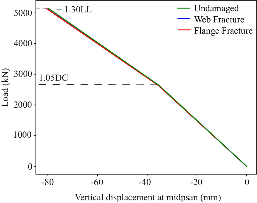
Fig. 12 depicts the static, load-displacement behavior (with displacement measured at midspan of Girder G2) of an undamaged bridge, compared with when a web in Girder G2 is fractured or when a bottom flange in Girder G2 fractured. Here, a static analysis has been performed using the Redundancy II load case to indicate the long-term behavior of the faulted structure. As shown by the similarities in behavior of the three compared systems, a fracture in the web or the flange of an interior girder has negligible impact on the system stiffness.
Conclusions
This paper has introduced the built-up PBTG system, including the design philosophy of a “kit-of-parts” approach. Numerical investigations of the behavior of a simple span and a two-span continuous bridge were performed, with the following key findings.
•
The feasibility of the built-up PBTG system has been demonstrated considering behavior under dead and live loads, as well as during construction.
•
Stresses under dead and live loads (without load factors) were all well below the yield strength of each component (i.e., less than 30% of the specified yield strength). Considering a Strength I load combination, the stresses increase but remain less than 45% of the specified yield strength.
•
Fatigue stress ranges for the steel sections are well below the nominal fatigue resistance for Category B design details for both positive and negative moment, with peak values being less than 25% of this limit. The stress ranges also satisfy the nominal fatigue resistance for Category C. This is important for the negative moment region where shear studs may control.
•
Stability factors during construction for both bridges exceeded 14, demonstrating the safety and constructability of the system.
•
Dynamic and static evaluations of internal redundancy indicate that built-up PBTGs are able to redistribute load effectively if either a web or bottom flange is fractured.
•
If a web or bottom flange is fractured, the resulting high-velocity stress wave creates strain rates in the dynamic region. As this type of event and the cold bending fabrication process both reduce the fracture toughness of the steel, it is important to evaluate the fracture toughness of steels to be used in built-up PBTGs.
•
During the short-term dynamic analysis, stresses in the web and flange oscillated after a web or flange was fractured, but with magnitudes well below the yield stress of each component and with strain rates in the intermediate region.
•
The long-term behavior of the faulted structure, evaluated via nonlinear static analyses, indicated a negligible loss of stiffness when either a web or bottom flange was fractured, as compared with an undamaged structure.
It is recommended that material certifications for the proposed cold bent web steel be approved by the engineer prior to fabrication to ensure adequate CVN impact energy, including a temperature shift that accounts for the cold working. The high CVN impact energy of transmission pole steels indicates that they are well suited for this application.
The focus of this paper is on the behavior of the two demonstration bridges as well as an evaluation of internal redundancy. Future work will include following the construction process of the two demonstration bridges and measuring the behavior of the built structures. Ultimately, this work aims to develop a comprehensive kit-of-parts catalog of built-up PBTGs for varying spans and arrangements that could be adopted by design engineers.
Data Availability Statement
All data, models, or code that support the findings of this study are available from the corresponding author upon reasonable request.
Acknowledgments
This work was supported by the Joint Transportation Research Program administered by the Indiana Department of Transportation (INDOT) and Purdue University. The authors appreciate the support of Study Advisory Committee Members Vin Bartucca, Patrick Conner, Andrew Fitzgerald, Jennifer Hart, Amy Huebschman, Jim Lesh, Seth Schickel, and Donald Shaw. The contributions of collaborators Tom Bieneman, Angela Pearl, and Skyler Coombs are gratefully acknowledged. The contents of this paper reflect the views of the authors, who are responsible for the facts and accuracy of the data presented herein, and do not necessarily reflect the official views or policies of the Indiana Department of Transportation or the Federal Highway Administration. These contents do not constitute a standard, specification, or regulation.
References
AASHTO. 2017. Load and resistance factor design (LRFD) bridge construction specifications. 4th ed. Washington, DC: AASHTO.
AASHTO. 2018. Guide specifications for analysis and identification of fracture critical members and system redundant members. 1st ed. Washington, DC: AASHTO.
AASHTO. 2020. Load and resistance factor design (LRFD) bridge design specifications, customary U.S. units. 9th ed. Washington, DC: AASHTO.
ABAQUS. 2022. ABAQUS/Standard analysis user’s manual. Waltham, MA: Dassault Systemes.
ASTM. 2020. Standard specification for high-strength low-alloy structural steel plate with atmospheric corrosion resistance. ASTM A871/A871M-20. West Conshohocken, PA: ASTM.
ASTM. 2021a. Standard specification for high-strength low-alloy columbium-vanadium structural steel. ASTM A572/A572M-21. West Conshohocken, PA: ASTM.
ASTM. 2021b. Standard specification for structural steel bridges. ASTM A709/A709M-21. West Conshohocken, PA: ASTM.
Barsom, J. 1975. “Development of the AASHTO fracture-toughness requirements for bridge steels.” Eng. Fract. Mech. 7 (3): 605–618. https://doi.org/10.1016/0013-7944(75)90060-0.
Barth, K., J. Mash, G. Michaelson, M. Barker, and D. Snyder. 2013. “Development of shallow press-brake formed tub girder for short-span steel bridges.” In Proc., 7th New York City Bridge Conf. Durability of Bridge Structures, 87–98. Boca Raton, FL: CRC Press.
Barth, K. E., and G. K. Michaelson. 2018. “Development and experimental testing of press-brake-formed steel tub girders for short span bridge applications.” Vol 1 of Development and feasibility assessment of shallow press-brake-formed steel tub girders for short span bridge applications. Washington, DC: AISI Steel Market Development Institute/Short Span Steel Bridge Alliance.
Barth, K. E., G. K. Michaelson, and M. G. Barker. 2015. “Development and experimental validation of composite press brake-formed modular steel tub girders for short-sapn bridges.” J. Bridge Eng. 20 (11): 04015007. https://doi.org/10.1061/(ASCE)BE.1943-5592.0000770.
Barth, K. E., G. K. Michaelson, and L. T. Kelly. 2018. “Development and experimental testing of press-brake-formed steel tub girders for short span bridge applications.” Vol. 2 of Experimental evaluation of non-composite shallow press-brake-formed steel tub girders. Washington, DC: AISI Steel Market Development Institute/Short Span Steel Bridge Alliance.
Barth, K. E., G. K. Michaelson, A. D. Roh, and R. M. Tennant. 2021. “Field determined live load distribution factors for modular press-brake-formed tub girders.” Transp. Res. Rec. 2675 (3): 1–7. https://doi.org/10.1177/0361198120983757.
Barth, K. E., G. K. Michaelson, and R. M. Tennant. 2020. “Fatigue performance of singular and modular press-brake-formed steel tub girders.” Bridge Struct. 16 (1): 3–13. https://doi.org/10.3233/BRS-200168.
CEN (European Committee for Standardization). 2005. Design of steel structures - Part 1–10: Material toughness and through-thickness properties. Eurocode 3: EN 1993-1-10. Brussels, Belgium: CEN.
Collins, W., R. Sherman, R. Leon, and R. Connor. 2016. “State-of-the-art fracture characterization. II: Correlations between Charpy V-notch and the master curve reference temperature.” J. Bridge Eng. 21 (12): 04016098. https://doi.org/10.1061/(ASCE)BE.1943-5592.0000955.
Connor, R. J., F. J. Bonachera Martin, A. Varma, Z. Lai, and C. Kormaz. 2018. Fracture-critical system analysis for steel bridges. NCHRP Rep. No. 883. Washington, DC: Transportation Research Board, National Academies of Sciences, Engineering, and Medicine.
Connor, R. J., and J. B. Lloyd. 2017. Maintenance actions to address fatigue cracking in steel bridge structures. NCHRP project 20-07 task 387. Washington, DC: Transportation Research Board, National Academies of Sciences, Engineering, and Medicine.
Connor, R., H. Gilmer, J. Lloyd, R. Medlock, and E. Wasserman. 2023. Implementation of redundancy terms under 2022 NBIS. Chicago: National Steel Bridge Alliance.
FHWA (Federal Highway Administration). 2015a. Steel bridge design handbook: Redundancy. Washington, DC: FHWA.
FHWA (Federal Highway Administration). 2015b. Steel bridge design handbook: Selecting the right bridge type. Washington, DC: FHWA.
FHWA (Federal Highway Administration). 2022. Memorandum: Inspection of nonredundant steel tension members. Washington, DC: FHWA.
Gerbo, E. J., A. P. Thrall, B. J. Smith, and T. P. Zoli. 2016. “Full-field measurement of residual strains in cold bent steel plates.” J. Constr. Steel Res. 127: 187–203. https://doi.org/10.1016/j.jcsr.2016.07.026.
Hebdon, M. H., F. J. Bonachera Martin, C. Kormaz, and R. J. Connor. 2017a. “Fracture resilience of steel built-up members subject to flexure.” J. Bridge Eng. 22 (7): 04017030. https://doi.org/10.1061/(ASCE)BE.1943-5592.0001059.
Hebdon, M. H., F. J. Bonachera Martin, C. Kormaz, and R. J. Connor. 2017b. “Load redistribution and remaining fatigue life of steel built-up members subject to flexure following a component failure.” J. Bridge Eng. 22 (9): 04017057. https://doi.org/10.1061/(ASCE)BE.1943-5592.0001087.
IBC (International Building Code). 2018. International building code. Falls Church, VA: International Code Council.
INDOT (Indiana Department of Transportation). 2017. Design manual - Chapter 407: Steel structure. Indianapolis: INDOT.
IRC (International Residential Code). 2018. International residential code. Falls Church, VA: International Code Council.
Keating, P. B., and L. C. Christian. 2012. Effects of bending and heat on the ductility and fracture toughness of flange plate. Technical Rep. No. FHWA/TX-10/0-4624-2. Texas: Texas Transportation Institute.
NBIS (National Bridge Inspection Standards). 2022. Subpart C - National bridge inspection standards (NBIS). Washington, DC: NBIS.
Sedlacek, G., et al. 2008. Commentary and worked examples to EN 1993-1-10 ‘Material toughness and through thickness properties’ and other toughness oriented rules in EN 1993. Luxembourg: Joint Research Centre European Commision.
Shergalis, M., and B. Law. 2016. “Steel bridge selection and design.” In Proc., Indiana Department of Transportation Bridge Design Conf. Chicago, IL: American Institute of Steel Construction.
Short Span Steel Bridge Alliance. 2020a. History and overview of press brake tub girders. Washington, DC: Short Span Steel Bridge Alliance.
Short Span Steel Bridge Alliance. 2020b. Folded and press brake options for accelerated bridge construction. Washington, DC: Short Span Steel Bridge Alliance.
Sun, M. 2014. “Mechanical behaviour of cold-formed hollow structural section material.” Ph.D. thesis, Univ. of Toronto.
Sun, M., and J. A. Packer. 2014. “Charpy V-notch impact toughness of cold-formed rectangular hollow sections.” J. Constr. Steel Res. 97: 114–126. https://doi.org/10.1016/j.jcsr.2014.02.005.
Tumbeva, M. D., A. P. Thrall, and T. P. Zoli. 2022. “Investigating the redundancy of steel truss bridges composed of modular joints.” J. Constr. Steel Res. 188: 107038. https://doi.org/10.1016/j.jcsr.2021.107038.
Valmont Structures. 2023. Valmont bridge solutions u-beam specification guide. Omaha, NE: Valmont Bridge Solutions.
Information & Authors
Information
Published In

Journal of Bridge Engineering
Volume 28 • Issue 12 • December 2023
Copyright
This work is made available under the terms of the Creative Commons Attribution 4.0 International license, https://creativecommons.org/licenses/by/4.0/.
History
Received: Oct 3, 2022
Accepted: Jun 24, 2023
Published online: Sep 22, 2023
Published in print: Dec 1, 2023
Discussion open until: Feb 22, 2024
Authors
Metrics & Citations
Metrics
Citations
Download citation
If you have the appropriate software installed, you can download article citation data to the citation manager of your choice. Simply select your manager software from the list below and click Download.