Analytical Solution of Terzaghi’s Ground Arch Model for Loads on Circular Tunnels
Publication: International Journal of Geomechanics
Volume 24, Issue 12
Abstract
To date, the important problem of Terzaghi’s ground arch model in 1946 has not been solved for loads on circular tunnels. This study comprehensively presented a general analytical solution of Terzaghi’s ground arch model for loads on circular tunnels by the limit equilibrium method, considering the complete boundary conditions of the loosening zone, the effects of water pressure, and the stiffness of the lining and ground. The proposed solution indicates the relationship between the load on circular tunnels and that on trapdoors, and there is a negative correlation between the lateral and vertical earth pressures in the ultimate state. Model tests and field measurements were used to verify the proposed solution. The results indicated that the proposed solution agrees well with the experimental results of circular tunnels in dense sand, loose sand, saturated sand, and saturated clay; the solution is significantly less than the design load from Terzaghi’s formula in good ground conditions. Moreover, the solution demonstrated an interesting rule: the distribution of total loads (including water pressure) on nonrigid circular tunnels is nearly uniform in saturated granular soil. A particular solution was obtained for circular tunnels in saturated granular soil. In addition, the vertical pressure on a circular tunnel in sand increases and the lateral pressure decreases as the groundwater table increases within the tunnel range; the case where the groundwater table is located at the crown is proved to be a critical condition for shield tunnels in sand.
Practical Applications
Previous studies indicate that the load on shield tunnels in good ground conditions would be overestimated by Terzaghi’s formula, which was proposed in 1943 and is widely adopted in tunnel design nowadays. In this study, a general analytical solution for loads on circular tunnels was established based on Terzaghi’s ground arch model, which was improved by Terzaghi in 1946 for arched tunnels but has not been solved. For various overburden depths, the proposed solution agrees well with the experimental results of circular tunnels in dense sand, loose sand, saturated sand, and saturated clay, but Terzaghi’s formula based on trapdoors fails to explain the test results of circular tunnels in sand. The proposed solution is significantly less than the design load from Terzaghi’s formula in good ground conditions. The solution is applicable for both shallow and deep circular tunnels, and it will be very helpful for the economical and rational design of shield tunnels normally in good ground conditions, such as sandy soil, crushed rock, and stiff or hard clayed soil.
Introduction
With the increasing need for underground facilities, shield tunneling has become one of the major construction methods in soils. In the design of shield tunnels, predicting the reduced load on the lining is a fundamental issue to be addressed. Based on trapdoor tests in sand, Terzaghi (1943) proposed an analytical solution to evaluate the reduced load on trapdoors, which is widely adopted in the design of shield tunnels (ITA 2000). However, the design load from Terzaghi’s formula based on trapdoors generally produced discrepancies from field observations and model tests of circular tunnels, especially in good ground conditions (Koyama 2003; Chen and Peng 2018; Wu et al. 2019; Atkinson et al. 1975; Zhou et al. 1999; Lee et al. 2004; Shahin et al. 2007). However, the discrepancy and relationship between the load on trapdoors and that on actual circular tunnels are still unclear in theory.
Based on experiments and experiences from practical arched tunnels, Terzaghi (1946) proposed a ground arch model and an empirical method to calculate design loads on deep tunnels in dense sand, loose sand, and crushed rock. In Terzaghi’s ground arch model for arched tunnels, the loosening zone is divided into three parts, and the roof support carries only the rectangular part above the roof. Terzaghi’s (1946) ground arch model is different from the trapdoor model adopted by Terzaghi’s (1943) formula, and it was improved by Terzaghi for actual arched tunnels. However, no analytical solution based on the model was obtained by Terzaghi, and Terzaghi’s empirical method is limited. Therefore, it is an important task to solve Terzaghi’s ground arch model for the load on circular tunnels.
Many researchers have investigated the reduced load on circular tunnels in soils using analytical methods (Atkinson and Potts 1977; Ono and Yamada 1993; Lee et al. 2004; Jeong et al. 2014; Cheng 2018; Chen and Peng 2018; Wu et al. 2019; Lin et al. 2022). For example, Cheng (2018) derived a semianalytical solution for the load on general arched tunnels in dry soil. Wu et al. (2019) developed a modified Terzaghi method for the arching effect induced by ground loss during tunneling in sand. Lin et al. (2022) proposed a new multiarch model for calculating the distribution of vertical earth pressure on a deep tunnel in dry sand. Some researchers have investigated the ground arch formation above arched tunnels using numerical methods (Chen et al. 2011; Yang et al. 2015; Kong et al. 2018). Kong et al. (2018) established a method to identify the extent of pressure arch by the inner boundary, outer boundary, and centroid line. Although various models and solutions for the load on circular tunnels have been developed, the analytical solutions presented so far are not based on Terzaghi’s ground arch model (Tien 1996; Moradi and Abbasnejad 2013), which may be due to its complexity.
Besides that, in the design of shield tunnels, Terzaghi’s formula does not account for the effect of water pressure and the two boundary conditions of the loosening zone: (1) the inclined sliding surfaces below the crown; and (2) the constraint condition of the tunnel supports. This paper aims to comprehensively present an analytical solution of Terzaghi’s ground arch model for loads on circular tunnels and overcome the aforementioned deficiencies. First, Terzaghi’s ground arch model was modified for an explicit expression, considering two pairs of vertical sliding surfaces above the crown and the sliding surfaces below the crown. Subsequently, a general solution for earth pressure on circular tunnels was derived by the limit equilibrium method, considering the constraint condition of the lining deformation and the effect of water pressure, while the relation between the load on circular tunnels and that on trapdoors was established. A particular solution was also derived for circular tunnels in saturated granular soil. Next, the proposed solution was compared with published experimental results of circular tunnels and field measurements in several soils. Finally, the difference between the proposed solution and Terzaghi’s formula, the effect of water pressure on earth pressure, and the critical condition for shield tunnels were discussed.
Terzaghi’s Ground Arch Model for Arched Tunnels and Explicit Model for Circular Tunnels
Terzaghi’s Ground Arch Model and Empirical Method for Arched Tunnels (Terzaghi’s Rock Load Theory)
Terzaghi (1946) proposed that the body of rock or sand that transfers the load will briefly be referred to as the ground arch, which is the shaded area (acdb) shown in Fig. 1(a). While the tunnel is being excavated, the mass of crushed rock or cohesionless sand constituting the ground arch tends to move into the tunnel. This movement is resisted by the friction along the lateral boundaries (ac and db) of this mass. However, it is inconvenient to use this configuration in actual calculations. Terzaghi, therefore, provided a simplified model to evaluate the load on an arched tunnel, which is illustrated in Fig. 1(b) for a circular tunnel. The roof support of the arched tunnel carries only the rectangular part above the tunnel roof, which is equivalent to a height Hp, and the other parts are carried by the wedges at the sides of the tunnel. Therefore, the vertical load on the roof of an arched tunnel is represented as follows:where pv = vertical load on the roof; Hp = equivalent overburden height; and γ = unit weight of soil.
(1)
Fig. 1. (a) Configuration of the ground arch; and (b) simplified model of the load on the tunnel support.
(Adapted from Terzaghi 1946.)
However, no analytical solution based on the ground arch model was obtained by Terzaghi. Hence, empirical values for Hp in sand and crushed rock were recommended by Terzaghi based on his model tests and experience (as shown in Table 1). According to Terzaghi’s (1946) tests and experience, the actual vertical load on the tunnel roof is normally much closer to the minimum than the maximum value. Terzaghi also suggested that the height Hp below the groundwater table should be roughly equal to twice that for dry sand. It should be noted that the empirical values are inconsistent with the theoretical values from Terzaghi’s formula.
| Sand | Above water table | Below water table | ||
|---|---|---|---|---|
| Hpmin/L | Hpmax/L | Hpmin/L | Hpmax/L | |
| Dense | 0.31 | 0.69 | 0.62 | 1.38 |
| Loose | 0.54 | 0.69 | 1.08 | 1.38 |
Source: Data from Terzaghi (1946).
Note: Hpmin and Hpmax = minimum and maximum of equivalent overburden height, respectively; L = Bt + Ht, where Bt and Ht are the width and height of an arched tunnel, respectively; and L = (D + h) for a circular tunnel, where D is the diameter and h is the height of the sliding surfaces below the crown.
Explicit Model of Terzaghi’s Ground Arch
Terzaghi’s ground arch model implicitly expresses that there are twin internal vertical sliding surfaces, which divide the loosening zone into three parts. For an explicit expression, Terzaghi’s ground arch model is modified to a failure model with external and internal sliding surfaces (the latter is an explicit form of the former), as shown in Fig. 2(a), because there are twin internal vertical sliding surfaces projected upward from near the tunnel springline in the model tests of circular tunnels (Atkinson et al. 1975; Lee et al. 2004). For a circular tunnel in good ground conditions, since the downward displacements of soil masses on the horizontal yielding strip BB′ are not uniformly distributed as those on a rigid trapdoor, the soil masses bounded by the internal sliding surfaces tend to produce more displacements than adjoining parts in the loosening zone. Therefore, the shear stress on the internal sliding surfaces can transfer the load on the roof onto the two Wedges ABE and A′B′E′ at both sides of the tunnel, resulting in the load on the roof being less than that on the wedges at both sides of the tunnel. Therefore, the formation mechanism of active arching above a circular tunnel differs from that above a trapdoor.
Unlike a trapdoor, there is a core ground arch supported on the inclined sliding Surfaces AB and A′B′ below the crown of a circular tunnel in good ground conditions, as shown in Fig. 2(b), which transfers the load from the tunnel roof onto the inclined sliding surfaces. The inclined sliding surfaces below the crown bear not only the frictions as indicated in Terzaghi’s ground arch model but also the normal forces, whose contributions to the reduced load on the tunnel roof are taken into account in this paper.
General Analytical Solution for Earth Pressure on Circular Tunnels in the Ultimate State Based on Explicit Model of Terzaghi’s Ground Arch
Assumptions
Based on the explicit model of Terzaghi’s ground arch, three assumptions are made:
1.
As shown in Fig. 3, the soil masses beside a circular tunnel will slide along the inclined sliding Surfaces AB and A′B′ in the ultimate state of soil failure, which are tangent to the circle and make an angle α with the vertical direction ( , where φ is the internal friction angle of soil);
2.
For the convenience of analysis, the external and internal sliding surfaces above the tunnel crown are assumed to be vertical, and the internal sliding Surfaces AE (A′E′) pass through Springline F (F′) and intersect at Point A (A′) with inclined sliding Surfaces AB and A′B′;
3.
The lining of a circular tunnel is assumed to be elastic.
The conventional analytical methods, such as Terzaghi’s formula, adopted two separate models (i.e., the trapdoor model and the retaining wall model) to calculate the vertical and lateral earth pressures, respectively, which act on circular tunnels simultaneously and are integrated into one model in this study.
When the overburden depth H > 2.5B (B is the equivalent yielding strip width) in a deep tunnel, the soil mass above the level of 2.5B from the crown is nearly unaffected by the arching effect and can be treated as a surcharge (Terzaghi 1943).
Relation Equations between the Earth Pressure on a Circular Tunnel and That on a Trapdoor
According to the explicit model of Terzaghi’s ground arch, the reduced load on the tunnel roof is equal to the difference between the weight of the soil masses in the loosening Zone ABCA′B′C′ (as shown in Fig. 3) and the vertical components of the frictional forces and the normal forces, which act on Boundaries ABC and A′B′C′. Thus, according to the vertical force equilibrium of the Element ABCA′B′C′, the vertical earth pressure pv on the tunnel roof is given bywhere D = diameter of a circular tunnel; T1 and T = frictional forces acting on Surfaces BC (B′C′) and AB (A′B′), respectively; N = normal force acting on Surfaces AB (A′B′); W1 and Wb = weights of the soil masses in Regions BB′C′C and ABDF (as shown in Fig. 4), respectively; p1 = surcharge on the ground; and a1 = half of the equivalent yielding strip width B (i.e., B = 2a1). For a circular tunnel with radius R, .
(2a)
Considering the nonuniform distribution of vertical pressure on Section BB′ and avoiding the introduction of the pressure distribution factor (Wu et al. 2019), the resultant Forces P2 and P3 on Sections ED and BE are adopted, respectively, as shown in Fig. 4. The vertical earth pressure pv immediately acting on the tunnel roof is generally treated as an average value for convenience and safety purposes. According to the vertical force equilibrium of the Element ABDF, the vertical earth pressure pv is given by
(2b)
According to the force equilibrium of Element BCC′B′ in the vertical direction, the load on Section BB′ (as shown in Fig. 3) is equal to
(3)
For a trapdoor in active arching, as shown in Fig. 5, if Trapdoor BB′ is under the same conditions as a circular tunnel and pa is the average pressure on Trapdoor BB′, the load on Trapdoor BB′ is equal towhere Ta = frictional force acting on the vertical sliding surfaces above Trapdoor BB′, and the average pressure pa on a trapdoor can be determined by Terzaghi’s formula expressed as expression (14).
(4)
Let us compare the friction force T1 acting on the vertical sliding Surfaces BC (B′C′) in the model of a circular tunnel with Ta in the model of a trapdoor. For the soil masses between the internal and external sliding surfaces, the vertical and horizontal stresses are greater than those above the Trapdoor BB′ because the internal sliding surfaces transfer the load above the tunnel roof to adjoining parts. The numerical simulation (Lin et al. 2022) also showed that the stresses adjoining the external surfaces above a circular tunnel are greater than the values from Terzaghi’s formula based on a trapdoor due to the nonuniform distribution of the vertical earth pressure. Correspondingly, the frictional force (T1) acting on the external Surfaces BC and B′C′ above the circular tunnel crown is not less than the frictional force (Ta) acting on the vertical sliding surfaces above Trapdoor BB′. Hence,
(5)
For the friction force on the vertical sliding Surfaces BC (B′C′) in Fig. 3, substituting Ta for T1 in Eq. (2a) can simplify the solution of the model and obtain a safer result, as the forces of the internal sliding surfaces cannot be determined. Therefore, by substituting Ta for T1 in Eq. (2a) first and then substituting Eq. (4) into (2a), or substituting Ta for T1 in Eq. (3) first and then substituting Eqs. (3) and (4) into (2b), the following expression can be obtained:
(6)
In good ground conditions, the lateral earth pressure ph acting on a circular tunnel can be simplified to a uniform pressure (ITA 2000). According to the horizontal force equilibrium of Element ABDF (as shown in Fig. 4) and Mohr–Coulomb failure criteria, the following equations can be obtained:where lateral earth pressure ph contains horizontal subgrade reaction and is similar to the load from field measurement, h is the height of sliding surfaces below the crown, . Here, c and φ are the cohesion and internal friction angle of the soil beside a tunnel, respectively.
(7)
(8)
An equation can be obtained from Eq. (6) × sin α − Eq. (7) × cos α; then, the normal force N can be obtained:
(9)
Substituting Eqs. (8) and (9) into Eq. (6), the relationship between the vertical earth pressure pv on a circular tunnel and the pressure pa on the corresponding trapdoor can be implicitly expressed as follows:or in terms of vertical resultant force Pv acting on half of a circular tunnelwhere ξ = 1 − tan α tan φ, λt = coefficient of total lateral pressure acting on a tunnel and can be written as follows:
(10a)
(10b)
(11)
Similarly, substituting Eqs. (8) and (9) into Eq. (7), the relationship between the lateral earth pressure ph on a circular tunnel and the pressure pa on the corresponding trapdoor can be implicitly expressed as follows:
(12)
Unlike the classical Rankine’s theory, Eq. (12) indicates that there is a negative correlation between the lateral and vertical earth pressures in the ultimate state. Eqs. (10a), (10b), and (12) are also suitable for general arched tunnels in good ground conditions, but the coefficient λt is different from that for circular tunnels.
For a circular tunnel, the weight of soil in Region ABFD can be calculated bywhere A = area of Zone ABDF; and γ = unit weight of soil. If the soil is below the groundwater table, the effective unit weight (γ′) and saturated unit weight (γsat) of the soil should be used for sand and clayed soils, respectively.
(13)
In the previous expressions, the pressure pa on a trapdoor in active arching can be calculated using Terzaghi’s formula (Terzaghi 1943), which considers only the sliding surfaces above the crown and is expressed aswhere K = ratio of lateral stress to vertical stress on the vertical sliding surfaces above the crown (K = 1.0 is suggested by Terzaghi); and H = overburden depth. In Eq. (14), c and φ are the cohesion and internal friction angle of the soil above a tunnel, respectively.
(14)
When a trapdoor is below the groundwater table, the earth pressure p2 at the groundwater table can be calculated according to Terzaghi’s formula, i.e.,where Hw = groundwater table from the trapdoor.
(15)
For a trapdoor in sand below the groundwater table, the earth pressure p2 at the groundwater table is treated as a surcharge of the soil mass below the groundwater table, and the effective unit weight γ′ of sand is adopted; thus, the earth pressure pa on a trapdoor below the groundwater table is calculated by the following equation:
(16)
Expression of Equivalent Overburden Height Hp in Sand or Crushed Rock
For a circular tunnel, according to Terzaghi’s empirical method, the minimum values of the equivalent overburden height Hpmin are 0.31(D + h) and 0.54(D + h) in dense and loose sand, respectively, but the empirical method cannot reflect the quantitative relationship between Hp and some important factors.
For sand or crushed rock, c = 0. Thus, Eq. (10a) can be simplified by trigonometric function transformations while excluding ξ, leading to the expression
(17)
When c = 0 and p1 = 0, according to Eqs. (1), (13), (14), and (17), the equivalent overburden height Hp carried on the tunnel roof is determined by the following equation:
(18)
The expression reveals that the equivalent overburden height Hp is related not only to the geometry of a tunnel but also to the internal friction angle of soil (φ), the depth of overburden (H), and especially the coefficient of total lateral pressure (λt).
Solution of the Coefficient of Total Lateral Pressure λt and the Vertical Earth Pressure pv
To calculate the earth pressure in Eqs. (10a) and (12), an important parameter, the coefficient of total lateral pressure λt, should be solved based on the constraint condition of the elastic deformation of the circular lining in the ultimate state. The lateral pressure ph contains the horizontal subgrade reaction, which is induced by the elastic deformation of the lining. For a circular tunnel, the horizontal subgrade reaction is usually simplified as a triangularly distributed load acting within the range of 45° with the horizontal direction (as shown in Fig. 6). By adopting the Winkler-type soil reaction, the subgrade reaction is estimated by the product of the coefficient of subgrade reaction (k) and the displacement of the lining (δ), which is caused by active loads; therefore, the model shown in Fig. 6 should be regarded as a model with ground-lining interaction (ITA 2000; Koyama 2003). The maximum subgrade reaction (pk) in the horizontal direction is at the springline and can be expressed as follows (ITA 2000):where pw = water pressure at the tunnel crown; qw = average value of horizontal water pressure acting on the tunnel; E = elastic modulus of the lining; I = moment of inertia of a unit width strip; η = reduction factor of the flexural rigidity of lining segments (EI) for the shield tunnel; and g′ = dead weight of the lining, which is given as g′ = γct, where γc = unit weight of the concrete lining; and t = thickness of the lining.
(19)
According to the equality of the resultant force, the subgrade reaction within the loosening zone of the ground can be converted into a uniform load (ps) (as indicated in Fig. 6), which is approximately calculated by the following equation:where .
(20)
Since the horizontal subgrade reaction develops after the lining has deformed, the lateral pressure ph given by Eq. (12) cannot be directly applied to a structural model. The lateral pressure excluding subgrade reaction can be applied to the structural model, and it is suggested by (RTRI 1997)where λ = coefficient of lateral earth pressure acting on a tunnel. Coefficient λ is approximately 0.45–0.55 for dense sandy soil and stiff clayed soil, 0.35–0.45 for very dense sandy soil and hard clayed soil (JSCE 2006), but a coefficient λ lower than that suggested can also be used in the design for safety purposes.
(21)
The lateral earth pressure ph acting on the circular tunnel contains two parts, i.e., the lateral pressure excluding the subgrade reaction and the horizontal subgrade reaction ps, as shown in Fig. 6. According to Eqs. (11) and (21), the lateral earth pressure ph can be expressed as follows:
(22)
Substituting Eqs. (19) and (20) into Eq. (22), the coefficient of total lateral pressure λt can be determined by the following equation:where γw = unit weight of water, n = ratio of lining stiffness to ground stiffness, which is given as n = ηEI/(kR4).
(23)
Substituting Eq. (23) into Eq. (10a), the vertical earth pressure pv acting on a circular tunnel can be explicitly expressed as follows:where ; and , particularly, when the groundwater table is above the crown. In the design of circular tunnels, the vertical earth pressure pv can be calculated by Eqs. (10a) and (23) or Eq. (24), while the lateral pressure excluding subgrade reaction can be obtained from Eqs. (21) and (24).
(24)
The proposed general solution accounts for the complete boundary conditions of the loosening zone: (1) the sliding surfaces above and below the crown; and (2) the constraint condition of the tunnel supports. According to Eq. (24), the vertical earth pressure pv varies with the stiffness of the lining and ground, water pressure, and dead weight of the segments. Therefore, the proposed general solution indicates the effects of water pressure and the stiffness of the lining and ground on earth pressure, which are important engineering factors and reflect ground–lining interaction. In contrast, the conventional methods, including Terzaghi’s formula, did not consider the effects of the factors.
It should be noted that the subgrade reaction due to the dead weight of the segments is considered in the solution because of the improvements in backfill grouting technology of shield tunnels, the employment of the circle retainer, and correct control of the jack thrust (Mashimo and Ishimura 2003). Otherwise, the dead weight of the segments of the shield tunnel should not be considered in Eqs. (23) and (24) for safety purposes.
Distribution Rules of Total Loads and Particular Solution for Earth Pressure on Circular Tunnels in Saturated Granular Soil
Distribution Rules of Total Loads Acting on Circular Tunnels in Saturated Granular Soil
When the granular soil (taking sand as an example) is saturated, the coefficient of total lateral pressure λt of a circular tunnel is significantly less than that with dry sand according to Eq. (23), as shown in Fig. 7 (Figs. 7–9 for , γ = 18kN/m3, λ = 0.5, R = 3 m, t = 0.3 m, η = 0.8, E = 3.45 × 10⁷ kN/m3, k = 40 × 103kN/m3); coefficient λt of a circular tunnel in dry sand is <1.0, as shown in Fig. 7, which means that the distribution of total loads is not uniform for a common circular tunnel in dry soil. However, for a circular tunnel in saturated granular soil, it is interesting that the ratio of horizontal loads (including water pressure) to vertical loads Khv is nearly equal to 1.0 under various overburden depths, according to the general solution. In other words, Eq. (25) is valid for circular tunnels in saturated granular soil, i.e.,
(25)
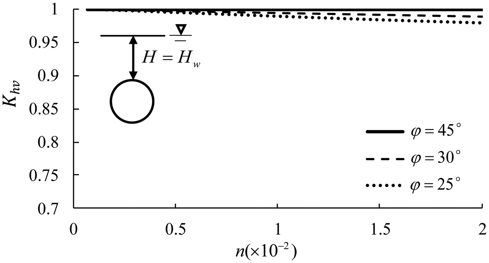
When a circular tunnel is below the groundwater table, the coefficient λt is significantly affected by the groundwater table Hw, but Fig. 8 shows that the ratio of horizontal loads to vertical loads Khv increases as the groundwater table Hw increases, and the ratio Khv is nearly equal to 1.0 when the groundwater table is located at the ground surface (i.e., Hw = H); even when the groundwater table is high, the ratio Khv is also close to 1.0. Under the condition of various ratios of lining stiffness to ground stiffness n and various internal friction angles, Fig. 9 indicates that the ratio Khv is nearly equal to 1.0 in saturated granular soil, and the relative difference is <3% for the common lining even when [usually for sandy soil (CEN 2007)]; the higher the internal friction angle, the closer the coefficient is to 1.0. Thus, it is demonstrated that Eq. (25) is valid for nonrigid circular tunnels in saturated granular soil with various internal friction angles.
Therefore, the general solution demonstrates an interesting rule: the distribution of total loads on nonrigid circular tunnels is nearly uniform in saturated granular soil. This rule is in agreement with the field measurements in the literature (Fujii et al. 2000; Koyama 2003), as shown in Fig. 10, except that the distribution of loads was affected by construction conditions. The uniform distribution of total loads (including subgrade reactions) is caused by the combined effects of ground–lining interaction and water pressure, but that does not mean that the bending moments of the circular lining are zero because of subgrade reactions induced by the lateral deformation of the circular lining. The proof shows that the general solution based on two-dimensional tunnels is reasonable, but the conventional arching theories based on a one-dimensional translation of trapdoors cannot explain the aforementioned phenomenon.
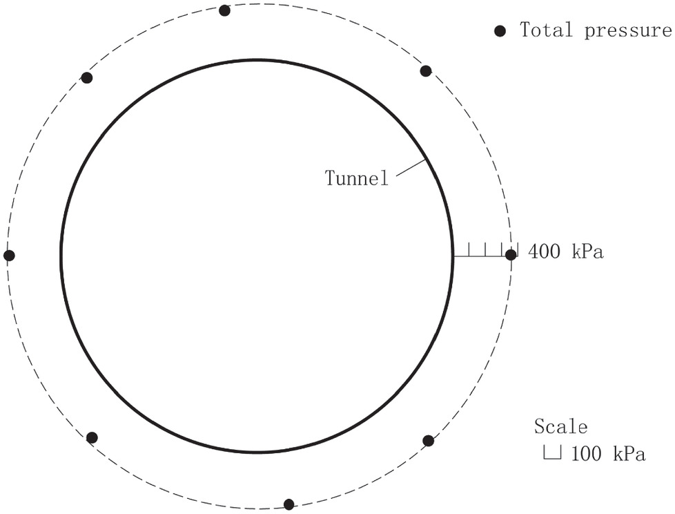
Fig. 10. Typical distribution of total loads on a circular tunnel in saturated granular soil.
(Data from Koyama 2003.)
Derivation of a Particular Solution
In saturated granular soil, the average value of horizontal water pressure qw is given by
(26)
Substituting Eq. (26) into Eq. (25), which is demonstrated in the previous section, the coefficient of total lateral pressure λt in saturated granular soil is expressed as follows:
(27)
Eq. (28b) reveals an interesting rule: the difference between the vertical and lateral earth pressures is approximately an invariant constant for a given circular tunnel in saturated granular soil.
By substituting Eq. (28a) into Eq. (12) and simplifying it, the vertical earth pressure pv can be explicitly expressed as follows:where .
(29)
Based on the uniform distribution of total loads acting on circular tunnels in saturated granular soil, the particular solution is established and more convenient for application than the general solution.
Comparison with Model Tests and Field Measurements of Circular Tunnels
Tests 1 and 2 in Dense Sand
The first test is the model test of circular tunnels in dense sand conducted by Atkinson et al. (1975). A rubber membrane was used as a circular tunnel lining supported by the applied air pressure, and the rubber membrane may be assumed to be perfectly flexible. The test was conducted by reducing the air pressure in stages until collapse occurred. The pressure in the final equilibrium was recorded in each test. As the air pressure inside the tunnel was uniform around the tunnel periphery, the coefficient of total lateral pressure λt is equal to 1.0.
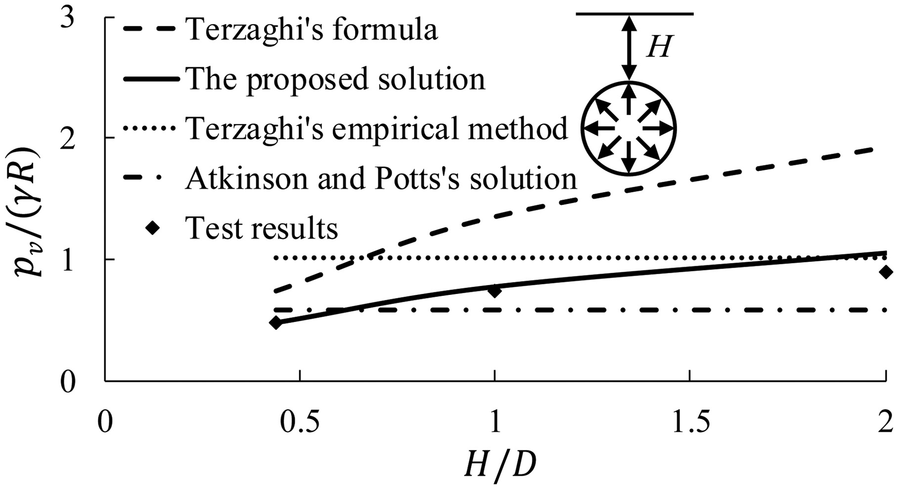
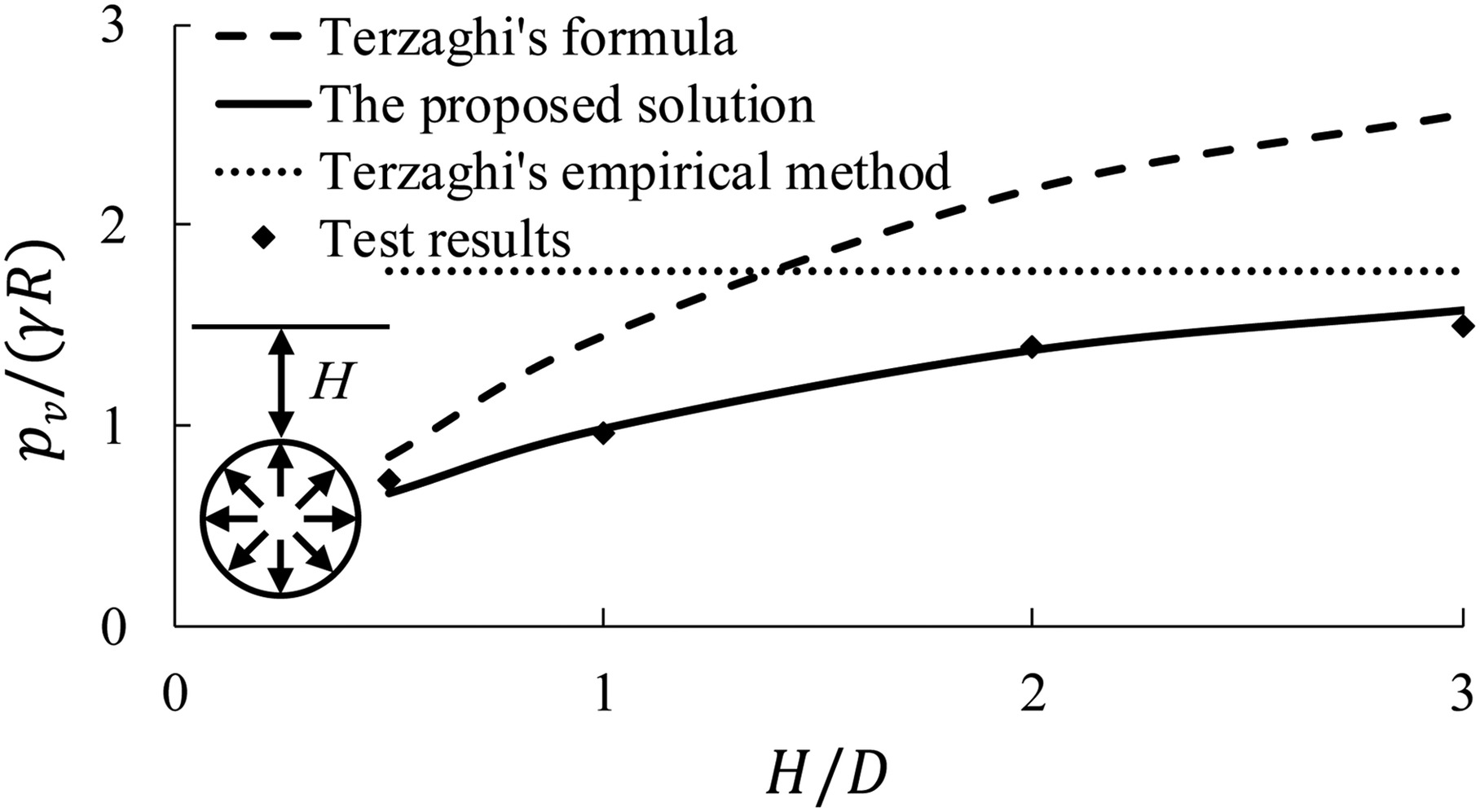
Fig. 11 shows the comparison of the vertical earth pressure from different methods with the model tests in the ultimate state. As shown in Fig. 11, the vertical earth pressures pv predicted by the proposed solution [Eq. (10a)] agree well with the experimental results for various overburden depths (the same result is also suitable for the lateral earth pressure), and the relative difference is 1%–16%; however, the values obtained from Terzaghi’s (1943) formula are 53%–113% higher than the test results. According to Hpmin from Table 1, the values given by Terzaghi’s (1946) empirical method are close to the test results only in the case of approximately H/D ≥ 2 for dense sand. According to the lower bound solution without surcharge loading (Atkinson and Potts 1977), the tunnel pressures are 20%–35% lower than the test results when H/D ≥ 1 and are unsafe for tunnel design. It is indicated that Terzaghi’s formula based on trapdoor tests cannot explain the test results of circular tunnels, while the proposed solution is valid and applicable for shallow and deep tunnels.
The second test is the centrifuge model test in dense sand conducted by Zhou et al. (1999). The model tunnel was a cylindrical rubber bag representing a 10-m-diameter tunnel at the prototype scale and was also supported by air pressures. The test procedure was similar to Test 1. As shown in Fig. 12, the vertical earth pressures pv predicted by the proposed solution [Eq. (10a)] are close to the test results for various overburden depths (the same result is also suitable for the lateral earth pressure). The other conclusions are also similar to those in Test 1.
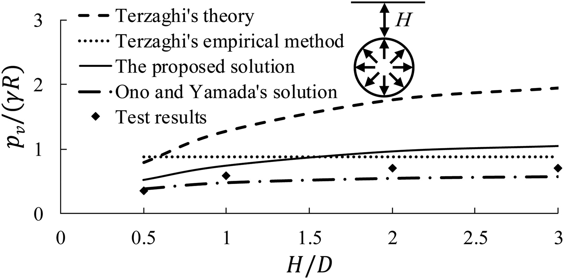
It is noted that the pressures from Ono and Yamada’s (1993) solution, which are almost uniform near the tunnel crown, are 18%–23% lower than the test results when H/D ≥ 1 and are unsafe for tunnel design.
Test 3 in Loose Sand
The third test was conducted by Shahin et al. (2007). The model consisted of a shim at the center of the circular tunnel surrounded by 12 segments. The load cells were attached to the block, which was placed around the segments of the tunnel. The equivalent friction angle of the aluminum rod mass was 30.5°, which corresponds to loose sand (CEN 2007). The results of the test with the tunnel invert fixed were adopted for comparison. As the lateral and vertical earth pressures were approximately equal to each other, λt ≈ 1.0.
As shown in Fig. 13, the vertical earth pressures pv predicted by the proposed solution [Eq. (10a)] are consistent with the experimental results (corresponding displacement of 1.0 mm) for various overburden depths (the same result is also suitable for the lateral earth pressure), and the relative difference is −7% to 6%; however, the values from Terzaghi’s formula (1943) are 18%–71% higher than the test results of circular tunnels. The values given by Terzaghi’s empirical method (1946) are close to the test results only when H/D ≥ 3 for loose sand.
Test 4 in Saturated Sand
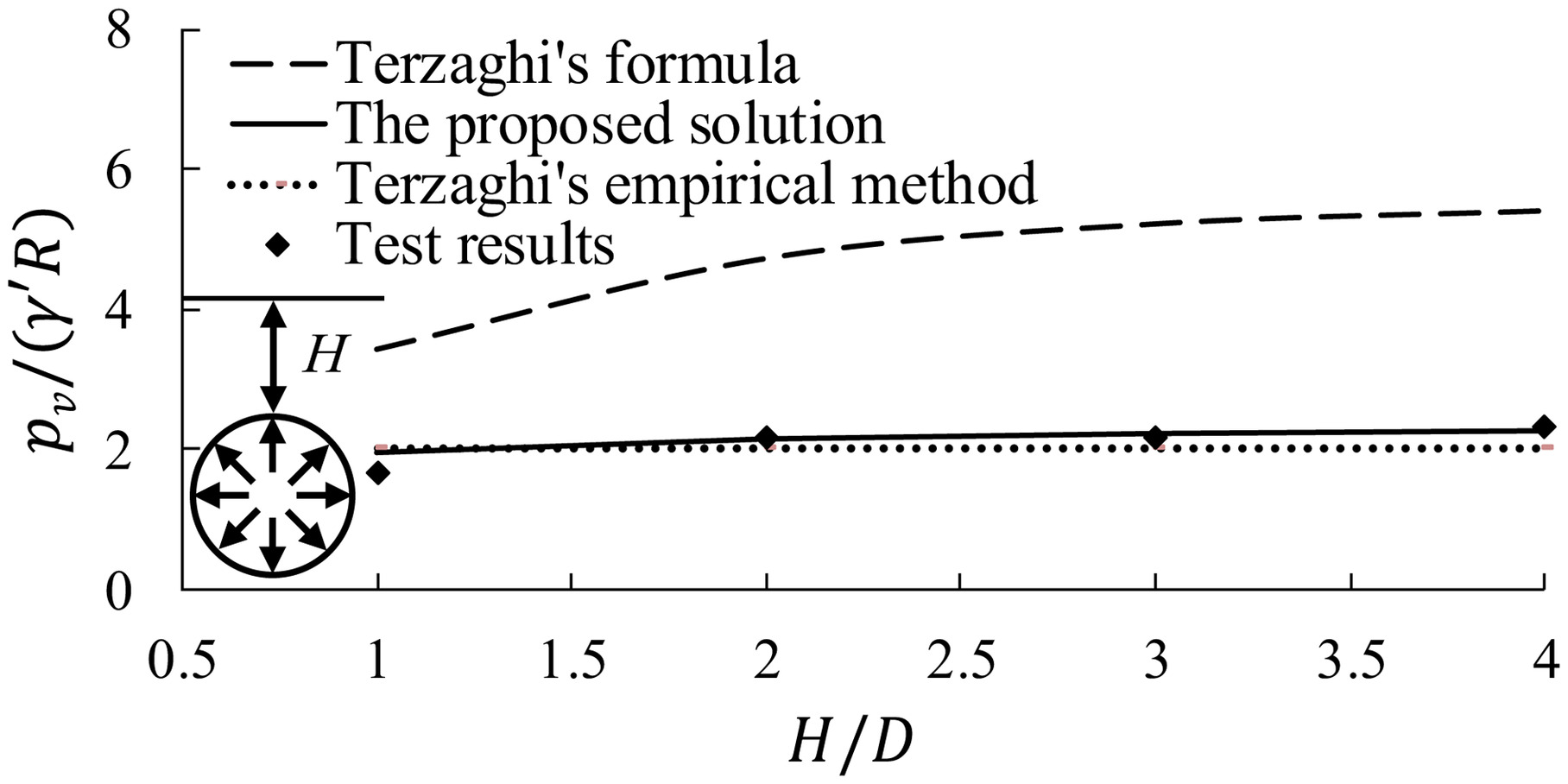
The fourth test was the centrifuge model test in saturated sand conducted by Lee et al. (2004). The model tunnel was a cylindrical rubber bag representing a 6-m-diameter tunnel at the prototype scale and was also supported by air pressures. The test procedure was similar to the Test 1 procedure. The ground material consisted of saturated quartz sand with φ, γ′, and Dr of 38°, 5.72 kN/m3, and 65%, respectively. As the air pressure inside the tunnel in saturated sand is uniform around the tunnel periphery, the ratio of the horizontal loads to the vertical loads Khv is equal to 1.0.
As shown in Fig. 14, the vertical earth pressures pv predicted by the proposed solution [Eq. (29)] agree well with the test results for various overburden depths (the same result is also suitable for the lateral earth pressure), and the relative difference is 1%–17%; however, the values obtained from Terzaghi’s (1943) formula are 104%–141% higher than the test results. The values given by Terzaghi’s (1946) empirical method agree well with the results of the circular tunnel in saturated sand with .
It should be noted that the ratio of lateral stress to vertical stress K on the vertical sliding surfaces is 1.0 in the above calculations, according to Terzaghi’s formula. The ratio K used by Lee et al. (2004) (K = 0.45 for φ = 38° in sand) was far less than the test results of active trapdoors, which showed that the value of K ranges between 1.0 and 1.3 (Terzaghi 1936; Evans 1983; Chevalier et al. 2012).
Test 5 in Saturated Clayed Soil
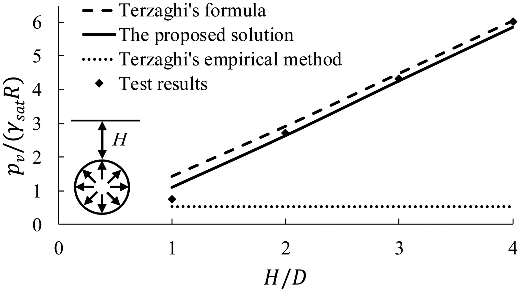
The fifth test is the centrifuge model test in saturated clayed soil conducted by Wu and Lee (2003). The model tunnel was also a cylindrical rubber bag representing a 6-m-diameter tunnel at the prototype scale and was also supported by air pressures. The test procedure was similar to Test 1. The saturated clayed soil had an undrained shear strength of 30–40 kPa after consolidation, which corresponds to medium clay. Due to the clayed soil, water pressure and soil pressure are integrated. As shown in Fig. 15, the vertical earth pressures pv predicted by both the proposed solution [Eq. (29)] and Terzaghi’s formula are close to the test results for various overburden depths. For safety purposes, the arching effect is normally considered for tunnels in stiff or hard clayed soil (JSCE 2006), which has an undrained shear strength >50 kPa. However, there was recently a case that considered the arching effect of deep tunnels in medium clay (Ito et al. 2021).
Case of Field Measurements in Gravel
Mashimo and Ishimura (2003) conducted elaborate field measurements of shield tunnels in gravel. The earth pressure and water pressure were measured in a stable state approximately 3 months after a segment ring was assembled. The overburden depth of Tunnel A with a diameter D of 6.2 m was 9.6 m. The ground conditions in the calculated section were given in the literature (Mashimo and Ishimura 2003); there was a layer of soft clay with a thickness of 3.2 m on the surface, and it should be treated as a surcharge. The groundwater table was estimated to be at the crown level, which is a critical condition, as mentioned in the “Discussion” section. The other parameters of the ground are k = 50 × 103kN/m3 and λ = 0.45. The parameters of the tunnel lining are t = 0.275m, EI = 5.45 × 10⁴kN · m2, η = 0.8, and n = 9.44 × 10⁻³.
The vertical and lateral earth pressures at the crown and springline were measured to be approximately 70 and 40 kPa, respectively (as shown in Table 2). The vertical pressure pv and lateral pressure ph calculated by the proposed solution [from Eqs. (24) and (12)] were 68 and 44 kPa, respectively. The results of the proposed analytical solution are approximately consistent with the field measurement results.
| Tunnel | Vertical pressure | Lateral pressure | ||
|---|---|---|---|---|
| Measured | Proposed solution | Measured | Proposed solution | |
| A | 70 | 68 | 40 | 44 |
Discussion
Difference between the Proposed Solution Based on Circular Tunnels and Terzaghi’s Formula Based on Trapdoors
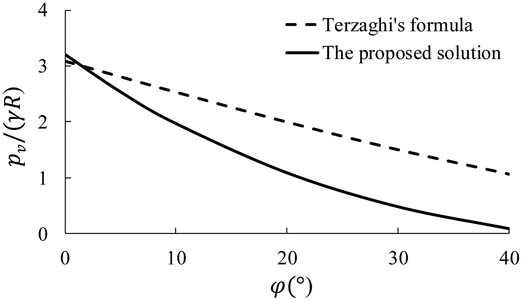
The proposed solution indicates the quantitative relationship between the vertical earth pressure on circular tunnels and that on trapdoors in the ultimate state. The vertical pressures from the proposed solution and Terzaghi’s formula decrease nonlinearly and linearly with the internal friction angle, respectively, as shown in Fig. 16 (Figs. 16, 18, and 19 for γ = 18 kN/m3, R = 3 m, t = 0.3 m, λ = 0.5, η = 0.8, E = 3.45 × 10⁷ kN/m3, k = 40 × 103 kN/m3, n = 1.92 × 10⁻²). Although the difference between them is small when the internal friction angle is low, the former is significantly less than the latter as the internal friction angle increases; for example, the proposed solution is 22%–91% lower than the design load from Terzaghi’s formula based on trapdoors when and c = 30 kPa in this case. This is due to the effect of a core ground arch near a circular tunnel in good ground conditions, as shown in Fig. 2(b), which is different from a trapdoor. Therefore, the proposed solution is very helpful for the economical and rational design of shield tunnels in good ground conditions.
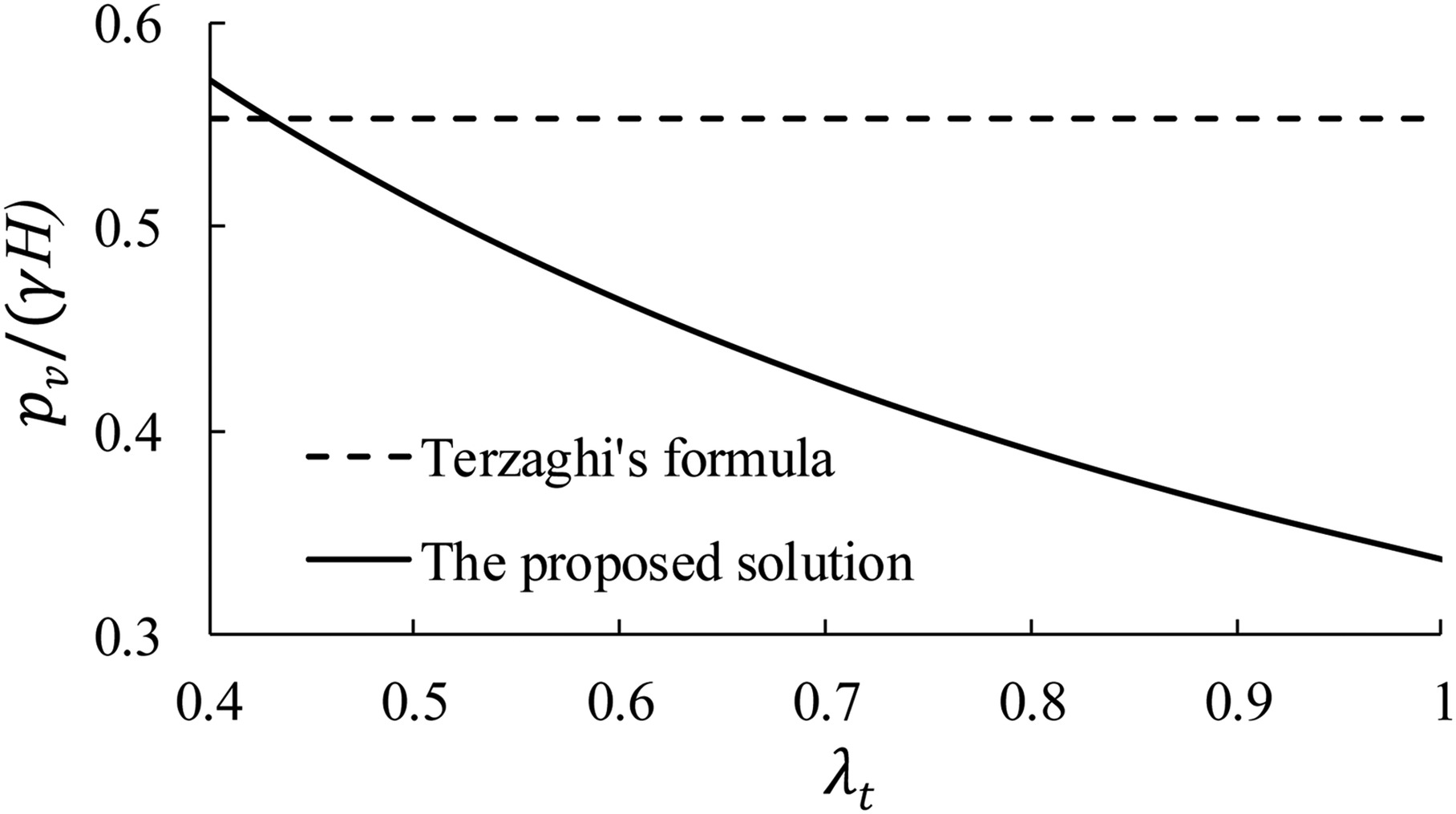
Eqs. (10a) and (12) reveal an interaction between the lateral and vertical earth pressures acting on circular tunnels in the ultimate state. According to Eq. (10a), the vertical earth pressure decreases with an increase in the coefficient of total lateral pressure (λt), and it reaches a minimum when λt = 1 (normally λt ≤ 1 in soils), as shown in Fig. 17 (Fig. 17 for , c = 0, γ = 18 kN/m3, R = 3 m). On the other hand, the lateral earth pressure increases linearly with a decrease in the vertical earth pressure, or there is a negative correlation between them, according to Eq. (12). This is because increasing the lateral pressure can enhance the bearing capacity of vertical stresses on Sections BE and B′E′ beside the tunnel [as shown in Fig. 2(a)], and the vertical stress above the tunnel roof decreases accordingly, and vice versa. This rule reveals the distribution mechanism of the lateral and vertical pressures acting on arched tunnels in the ultimate state. However, the vertical earth pressure from Terzaghi’s formula based on trapdoors is independent of the lateral earth pressure acting on circular tunnels.
Effect of Water Pressure on Earth Pressure Acting on Circular Tunnels in Sand and the Critical Condition for Tunnel Design
The safety of the critical sections should be checked during tunnel design, and ITA (2000) suggested that the section with the lowest groundwater table be taken as the critical condition for shield tunnel design.
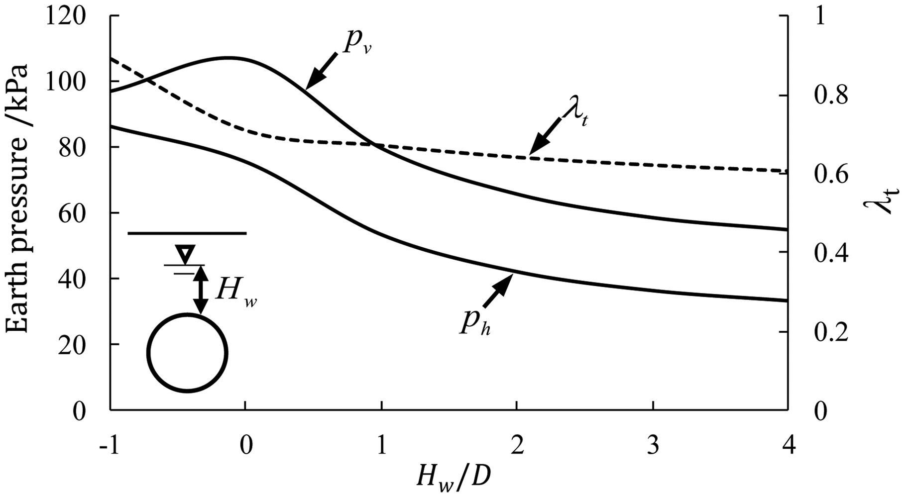
When the groundwater table Hw increases within the tunnel range (i.e., −1 ≤ Hw/D ≤ 0), the coefficient of total lateral pressure λt and the lateral earth pressure ph decrease, as seen in Fig. 18, because the subgrade reaction is restrained due to water pressure; however, the vertical earth pressure pv on the tunnel increases with increasing groundwater table because there is a negative correlation between the vertical and lateral earth pressures on circular tunnels in the ultimate state. When the groundwater table increases beyond the crown (i.e., Hw/D > 0), both the vertical and lateral earth pressures decrease nonlinearly, as shown in Fig. 18, because the effective stress below the groundwater table decreases. Therefore, when the groundwater table is located at the crown level, the vertical pressure reaches its maximum, and the case is a critical condition for the design of shield tunnels in the sand.
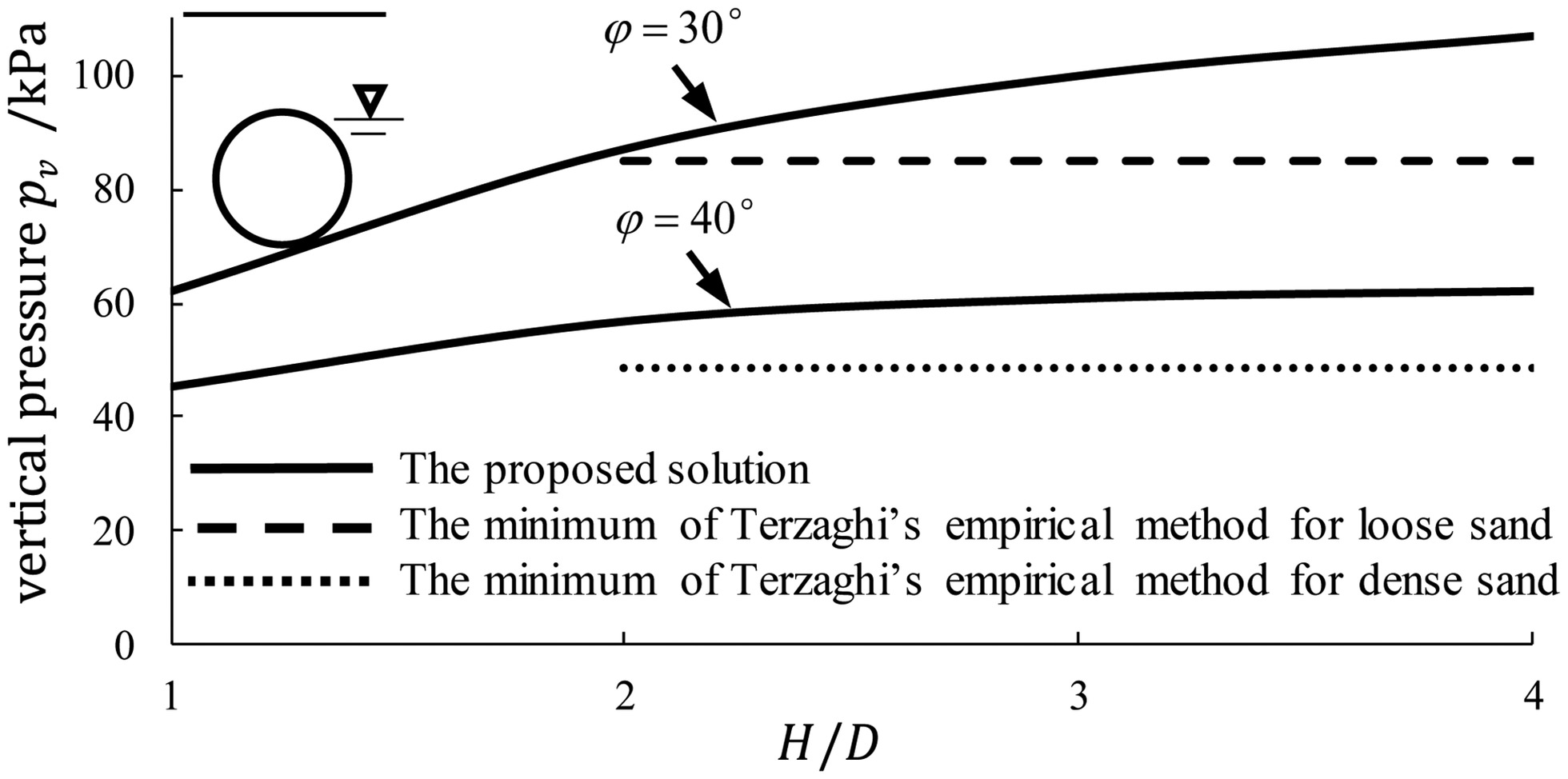
It is shown in Fig. 18 that water pressure has a significant effect on earth pressure acting on a circular tunnel in sand. Therefore, Terzaghi’s suggestion that the height Hp below the groundwater table should be roughly equal to twice that for dry sand is not reasonable. When the groundwater table is located at the crown level, Fig. 19 indicates that the minimum loads from Terzaghi’s empirical method for dense sand (about ) and loose sand (about ) are obviously less than the values from the proposed solution for and , respectively. This is because Terzaghi’s empirical method cannot express the variation in the load with some factors, including the groundwater table, the overburden depth, and the soil properties; thus, it is very limited.
Conclusions
The important problem of Terzaghi’s ground arch model (1946) is successfully solved for loads on circular tunnels in this study. Based on the explicit model of Terzaghi’s ground arch, a general analytical solution for earth pressure on circular tunnels is established according to the limit equilibrium method, considering the complete boundary conditions of the loosening zone. The expression of equivalent overburden height in sand is established, and a particular solution is also obtained for circular tunnels in saturated granular soil. Model tests and field measurements of circular tunnels in several soils are used to verify the proposed solution. The following conclusions are drawn:
1.
The proposed solution indicates the quantitative relationship between the vertical (or lateral) earth pressure on circular tunnels and that on trapdoors in the ultimate state. The solution also indicates the effects of water pressure and the stiffness of the lining and ground on earth pressure, which reflects ground–lining interaction.
2.
The proposed solution reveals that there is an interaction between the lateral and vertical earth pressures in the ultimate state, which presents a negative correlation. The vertical pressure reaches its minimum when λt = 1. The solution based on circular tunnels is significantly less than the design load from Terzaghi’s formula based on trapdoors in good ground conditions due to the effect of a core ground arch.
3.
Compared with the experiments of circular tunnels, the general and particular solutions agree well with the experimental results of circular tunnels in dense sand, loose sand, saturated sand, and saturated clay, but Terzaghi’s formula based on trapdoor tests fails to explain the test results of circular tunnels in sand. The proposed solution reasonably illustrated the field measurements of circular tunnels in gravel.
4.
The general solution demonstrates an interesting rule: the distribution of total loads on nonrigid circular tunnels is nearly uniform in saturated granular soil, and the difference between the vertical and lateral earth pressures is approximately an invariant constant for shield tunnels in saturated granular soil.
5.
It is revealed that the vertical pressure on a circular tunnel in sand increases and the lateral pressure decreases as the groundwater table increases within the tunnel range. The coefficient of total lateral pressure λt decreases with an increasing groundwater table. When the groundwater table is located at the crown, the vertical pressure reaches its maximum, and this is a critical condition for the design of circular tunnels in sand.
Data Availability Statement
All data, models, and codes that support the findings of this study are available from the corresponding author upon reasonable request.
References
Atkinson, J. H., E. T. Brown, and M. Potts. 1975. “Collapse of shallow unlined tunnels in dense sand.” Tunnels Tunnelling 3: 81–87.
Atkinson, J. H., and D. M. Potts. 1977. “Stability of a shallow circular tunnel in cohesionless soil.” Géotechnique 27 (2): 203–215. https://doi.org/10.1680/geot.1977.27.2.203.
CEN (European Committee for Standardization). 2007. Geotechnical design—Part 2: Ground investigation and testing. Eurocode 7. London: Standards Policy and Strategy Committee.
Chen, C. N., W.-Y. Huang, and C.-T. Tseng. 2011. “Stress redistribution and ground arch development during tunneling.” Tunnelling Underground Space Technol. 26 (1): 228–235. https://doi.org/10.1016/j.tust.2010.06.012.
Chen, K.-H., and F.-L. Peng. 2018. “An improved method to calculate the vertical earth pressure for deep shield tunnel in Shanghai soil layers.” Tunnelling Underground Space Technol. 75: 43–66. https://doi.org/10.1016/j.tust.2018.01.027.
Cheng, X. H. 2018. “An arching theory for arched tunnels based on interaction between the lateral and vertical pressure in good ground.” In Proc., of GeoShanghai 2018 Int. Conf., 164–180. Singapore: Springer.
Chevalier, B., G. Combe, and P. Villard. 2012. “Experimental and discrete element modeling studies of the trapdoor problem: Influence of the macro-mechanical frictional parameters.” Acta Geotech. 7 (1): 15–39. https://doi.org/10.1007/s11440-011-0152-5.
Evans, C. H. 1983. “An examination of arching in granular soils.” S.M. thesis, Dept. of Civil Engineering, Massachusetts Institute of Technology.
Fujii, K., H. Mashimo, and T. Ishimura. 2000. “Load acting on shield tunnel in gravel ground.” In Vol. 10 of Proc. Tunnel Engineering JSCE, 257–262. Tokyo, Japan: Japan Society of Civil Engineers (JSCE).
ITA (International Tunnelling Association). 2000. “Guidelines for the design of shield tunnel lining.” Tunnelling Underground Space Technol. 15: 303–331. ITA Working Group No. 2. https://doi.org/10.1016/S0886-7798(00)00058-4.
Ito, Y., S. Shinoguchi, S. Oka, A. Afshani, S. Kaneko, J. Saito, and H. Akagi. 2021. “Evaluation of vertical effective earth pressure for shield segment design in medium stiff clay.” J. Jpn. Soc. Civ. Eng., Ser. F1 (Tunnel Eng.) 77 (2): I_44–I_57. https://doi.org/10.2208/jscejte.77.2_I_44.
Jeong, S.-S., Y.-C. Han, Y.-M. Kim, and D.-H. Kim. 2014. “Evaluation of the NATM tunnel load on concrete lining using the ground lining interaction model.” KSCE J. Civ. Eng. 18: 672–682. https://doi.org/10.1007/s12205-014-0597-9.
JSCE (Japanese Society of Civil Engineering). 2006. Japanese standard and explanation of tunnel engineering (shield tunnelling). Tokyo: JSCE.
Kong, X. X., Q. S. Liu, Q. B. Zhang, Y. X. Wu, and J. Zhao. 2018. “A method to estimate the pressure arch formation above underground excavation in rock mass.” Tunnelling Underground Space Technol. 71: 382–390. https://doi.org/10.1016/j.tust.2017.09.004.
Koyama, Y. 2003. “Present status and technology of shield tunneling method in Japan.” Tunnelling Underground Space Technol. 18: 145–159. https://doi.org/10.1016/S0886-7798(03)00040-3.
Lee, C.-J., K.-H. Chiang, and C.-M. Kuo. 2004. “Ground movement and tunnel stability when tunneling in sandy ground.” J. Chin. Inst. Eng. 27 (7): 1021–1032. https://doi.org/10.1080/02533839.2004.9670957.
Lin, X.-T., R.-P. Chen, H.-N. Wu, F.-Y. Meng, D. Su, and K. Han. 2022. “Calculation of earth pressure distribution on the deep circular tunnel considering stress-transfer mechanisms in different zones.” Tunnelling Underground Space Technol. 119: 104211. https://doi.org/10.1016/j.tust.2021.104211.
Mashimo, H., and T. Ishimura. 2003. “Evaluation of the load on shield tunnel lining in gravel.” Tunnelling Underground Space Technol. 18: 233–241. https://doi.org/10.1016/S0886-7798(03)00032-4.
Moradi, G., and A. Abbasnejad. 2013. “The state of the art report on arching effect.” J. Civ. Eng. Res. 3 (5): 148–161.
Ono, K., and M. Yamada. 1993. “Analysis of the arching action in granular mass.” Géotechnique 43 (1): 105–120. https://doi.org/10.1680/geot.1993.43.1.105.
RTRI (Railway Technical Research Institute). 1997. Design standard for railway structures (shield-driven tunnel), 47–61. Maruzen, Japan: RTRI.
Shahin, H. M., T. Nakai, F. Zhang, M. Kikumoto, Y. Tabata, and E. Nakahara. 2007. “Model tests and numerical simulations on shallow circular tunneling.” In Proc., 19th Central Japan Geotechnical Symp., 131–138. Tokyo, Japan: Japan Society of Civil Engineers (JSCE).
Terzaghi, K. 1936. “Stress distribution in dry and saturated sand above a yielding trap-door.” In Proc., of Int. Conf. of Soil Mechanics and Foundation Engineering, 35–39. Cambridge, MA: Harvard University.
Terzaghi, K. 1943. Theoretical soil mechanics. New York: Wiley.
Terzaghi, K. 1946. “Rock defects and loads on tunnel supports.” In Rock tunneling with steel supports, edited by R. V. Proctor and T. L. White, 15–99. Youngstown, OH: Commercial Shearing and Stamping.
Tien, H. J. 1996. “A literature study of the arching effect.” M.S. thesis, Dept. of Civil and Environmental Engineering, Massachusetts Institute of Technology.
Wu, B. R., and C. J. Lee. 2003. “Ground movements and collapse mechanism induced by tunnelling in clayey soil.” Int. J. Phys. Modell. Geotech. 4: 15–29.
Wu, J., S.-M. Liao, and M.-B. Liu. 2019. “An analytical solution for the arching effect induced by ground loss of tunneling in sand.” Tunnelling Underground Space Technol. 83: 175–186. https://doi.org/10.1016/j.tust.2018.09.025.
Yang, J. H., S. R. Wang, Y. G. Wang, and C. L. Li. 2015. “Analysis of arching mechanism and evolution characteristics of tunnel pressure arch.” Jordan J. Civ. Eng. 9 (1): 125–132.
Zhou, X. W., J. L. Pu, and C. G. Bao. 1999. “A study of the movement and failure characteristics of sand mass above the crown of a tunnel.” Rock Soil Mech. 20 (2): 32–36.
Information & Authors
Information
Published In

International Journal of Geomechanics
Volume 24 • Issue 12 • December 2024
Copyright
This work is made available under the terms of the Creative Commons Attribution 4.0 International license, https://creativecommons.org/licenses/by/4.0/.
History
Received: Nov 21, 2023
Accepted: Jun 5, 2024
Published online: Sep 26, 2024
Published in print: Dec 1, 2024
Discussion open until: Feb 26, 2025
Authors
Metrics & Citations
Metrics
Citations
Download citation
If you have the appropriate software installed, you can download article citation data to the citation manager of your choice. Simply select your manager software from the list below and click Download.