A Test of Height Transfer Using Vertical Deflection Measurements by the Digital Zenith Camera VESTA
Publication: Journal of Surveying Engineering
Volume 149, Issue 4
Abstract
A test application of a height transfer method employing quasi-geoid undulation extrapolation using vertical deflection (VD) measurements obtained by the digital zenith camera VESTA (VErtical by STArs) is described. This method in combination with ellipsoidal height measurements by global navigation satellite system (GNSS) may provide a cheaper and more convenient alternative to classical geometrical leveling, particularly for long distances and/or when natural or administrative obstacles are present. VD measurements were taken along a 4.5-km traverse of the first-order leveling points located at both ends and in the middle, with GNSS measurements taken at the first-order leveling points. The height transfer results were then compared to the existing network data from the national database. The agreement between the height transfer results and the leveling network data was within the expected deviations. Possible error sources were evaluated, and requirements for VD measurement point selection were formulated.
Introduction
Geometrical leveling is traditionally used to transfer height differences above the sea-level surface (geoid) between leveling network points. However, this procedure consumes time and human resources, especially over long distances and when topographic or administrative obstacles are present. Alternative to geometrical leveling is the use of accurate data of geoid undulations in combination with ellipsoidal GNSS heights , providing normal (or orthometric) height . This can do the job much faster and more easily, but unfortunately the geoid surface properties are generally not known with the accuracy required for precise leveling. Instead, measurements of vertical deflection (i.e., the inclination of the geoid surface with respect to the reference ellipsoid surface) along a traverse between leveling points might provide the necessary data. Such measurements can be collected independently for intermediate points, old data can be used together with new measurements, and the distance between measurement points may be an order of magnitude greater than that for geometrical leveling.
Vertical deflection measurements by digital zenith cameras have been used to determine geoid undulation (Hirt and Flury 2008; Voigt and Denker 2014; Schack et al. 2018). Hirt and Flury described an astronomical-topographical leveling method using rather sparse VD measurements with an accuracy of . These measurements were densified by interpolating VDs between measured points using a digital terrain model (DTM). Hirt and Flury showed that an accuracy of 0.05–0.1 ppm with point spacing ranging from several hundred meters to two kilometers in mountainous areas can be achieved.
Hirt et al. (2011) used a combination of traditional and astronomical leveling, known as geometric-astronomic leveling, to validate GNSS-derived ellipsoidal heights. The accuracy of ellipsoidal height differences between adjacent benchmarks at a distance of 1–2 km obtained from geometric-astronomical leveling was found to be . Comparison of these results with GNSS-derived height differences obtained by sophisticated methodology showed an agreement at a level of a few millimeters for inter-station distances of approximately one to two kilometers.
Schack et al. (2018) used astronomical-topographical leveling for determining geoid undulation. In their study, VDs were measured using the QDaedalus (Guillaume et al. 2012) system with an accuracy of in the rough topography of the coast of Perth, Australia. The aim was to assess the accuracy of global and regional gravimetric quasi-geoid models, in several of which inconsistencies were revealed.
In the US, several geoid slope validation surveys have been conducted over the years to determine geoid undulations along the traverse using different techniques and technologies. In 2011, a survey was conducted in Texas over smooth terrain (Smith et al. 2013). Another survey was conducted in 2014 in Iowa, crossing the Midcontinent Rift (Wang et al. 2017). In 2017, a survey was conducted in mountainous terrain in Colorado using spirit leveling and VD measurements taken at a distance of 1.6 km between points and including absolute gravimeter measurements and a refined methodology for spirit leveling refraction correction (van Westrum et al. 2021). The precision of the VD measurements from this last survey was 0.04 arcsec. Two geoid profiles derived from GNSS/leveling and VD data agreed better than over the 360-km route.
In this study, a test application of height transfer employing quasi-geoid undulation extrapolation was undertaken. The method employed VD measurements obtained by the digital zenith camera (DZC) VESTA (VErtical by STArs) in combination with ellipsoidal height measurements by GNSS. To test this method, dense VD measurements were taken along a 4.5-km traverse of the first-order leveling points. GNSS height measurements were obtained at three first-order leveling points located at both ends of the traverse and in the middle. The height transfer results were then compared with existing network data from the national geodetic database.
Measurements
A test campaign was carried out in 2021–2022 to transfer height between three first-order leveling network points in West Latvia. The aim was to check the properties and establish the procedure for such measurements and data processing. The three network points were located on relatively flat terrain along a generally north–south road, with a distance slightly above 2 km between them (4.5 km between endpoints of the traverse as shown in Fig. 1).
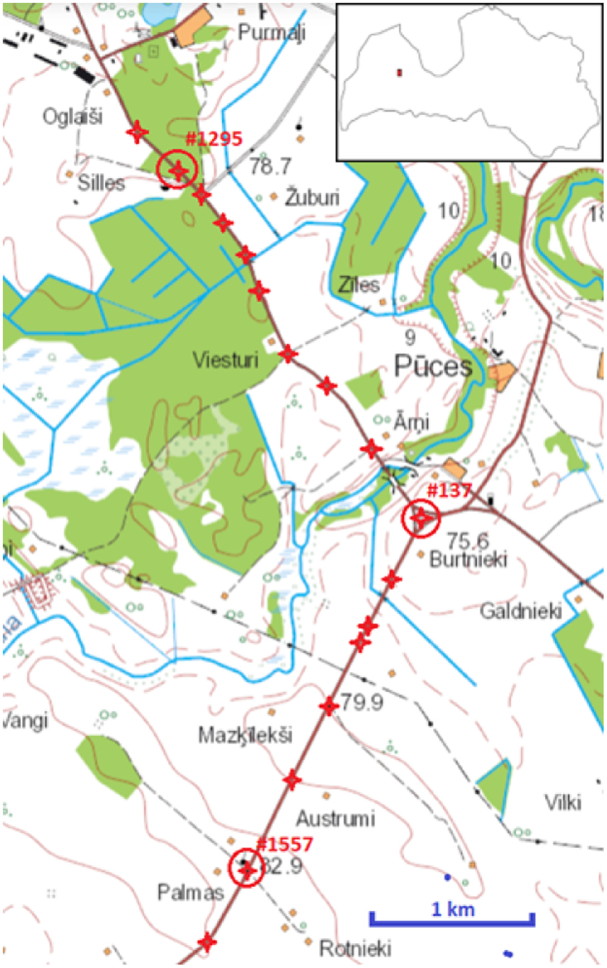
The DZC VESTA, designed at the Institute of Geodesy and Geoinformatics of the University of Latvia (Zariņš et al. 2016), was used to perform the VD measurements. Previously, VD data obtained by VESTA was used for determination of a quasi-geoid model of Latvia (Morozova et al. 2021). VD values were measured at 18 points along the north–south road (Fig. 1), with an average distance of about 250 m between measurement points. The measurement session at each point lasted between 50 min and 1 h including 24 to 30 rotation positions of the DZC and 3,000–4,000 National Marine Electronics Association (NMEA) coordinate messages of the GNSS receiver. This allowed determination of geocentric coordinates with accuracy [autonomous mode using satellite based augmentation system (SBAS)] and VDs with accuracy.
On April 15, 2021, ellipsoidal heights for the three selected leveling network points were obtained by simultaneous static GNSS measurements lasting approximately 6 to 7 h using available equipment. Topcon GR-5 receivers (Topcon Positioning Systems, Tokyo) were used directly on the Points 0137 and 1557, and a Stonex S700A receiver (STONEX® Srl, Milan, Italy) was used on Point 1295. Data was post-processed using Bernese GNSS Software v.5.2 in double-difference mode along with GPS and Globalnaya Navigatsionnaya Sputnikovaya Sistema (GLONASS) systems. Type mean phase center variation (PCV) corrections were applied to both types of antenna. Twenty-seven LatPos [Latvian continuously operating reference station (CORS) network] stations were used as references to ensure baseline lengths of a few tenths of a kilometer. Their known coordinates in LKS-92 (Legal Acts of the Republic of Latvia 2011) were used. The final coordinates were converted from geocentric to ellipsoidal.
The Latvian first-order leveling database provided by the Latvian Geospatial Information Agency (LGIA n.d.) was used to obtain normal heights in LAS-2000.5 (the Latvian height system) for Points 1295, 0137, and 1557, which had been determined by geometrical leveling in 2007. According to Republic of Latvia Cabinet Regulation No. 879, (Legal Acts of the Republic of Latvia 2011), first-order leveling has to achieve standard deviation. However, there are no publications on point height accuracy or point-to-point height variation estimates for this network.
For test purposes, the GGMplus geoid model (Hirt et al. 2013) was used as the source of alternative VD and geoid height data. GGMplus was selected because it possesses three properties that are rarely found in similar models: high spatial resolution (7.2 arcsec, approximately 200 m), topography gravity effects based on Shuttle Radar Topography Mission (SRTM) results (Farr et al. 2007), and VD values in the model data.
Data Processing
For each VD measurement point, geocentric radius-vector, , angular geocentric (ellipsoidal) equatorial coordinates , and VD components were obtained.
For each pair of sequential measurement points , the following were calculated:
•
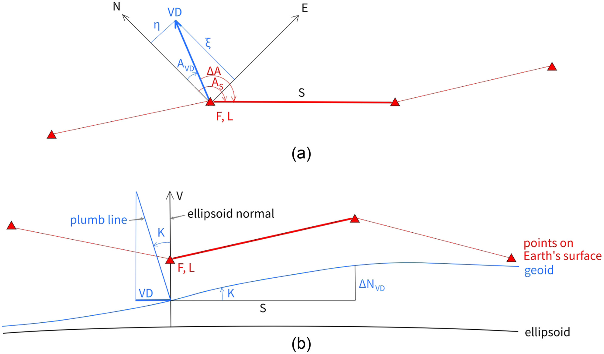
Vector between points distance between points (Fig. 2).
•
Averaged components of VD
(1)
(2)
•
Horizontal north-pointing and vertical unit vectors and in the topocentric ellipsoidal coordinate system (for a site with geocentric latitude and longitude )
(3)
(4)
•
Azimuth of :
(5)
•
Azimuth of VD projection to ellipsoidal tangent plane
(6)
•
Angle between and VD projection to tangent plane
(7)
•
Inclination of geoid’s surface to ellipsoid surface in the direction of
(8)
•
Extrapolated change in geoid undulation (distance between geoid and ellipsoid surfaces) along (assuming constant within )
(9)
The changes in geoid undulation between the geometric leveling points situated near the endpoints and the midpoint of the traverse (Fig. 1) were obtained by summing the values of along the route. To compare the results of geoid undulation extrapolation with existing leveling network data, the difference between the catalog value of normal height and measured ellipsoidal height (representing the sum of and geoid undulation value at that point) was calculated as . The change in this estimated value of between the network points was then compared with the change in extrapolated undulation from Eq. (9). This comparison is presented in Table 1.
| Point | Catalog normal height (m) | Ellipsoidal height (m) | Geoid undulation, (m) | relative to Point 1295 (mm) | relative to Point 1295 (mm) |
|---|---|---|---|---|---|
| 1295 | 81.009 | 0 | 0 | ||
| 137 | 75.750 | ||||
| 1557 | 82.106 |
Note: Leveling network point normal heights from catalog; ellipsoidal heights measured by GNSS; geoid undulation and geoid undulations relative to Point 1295 obtained from GNSS measured ellipsoidal heights and catalog normal heights; geoid undulations obtained from VD measurements; ; and assumed.
Error Estimation
The height transfer error estimate contains several components. The direct effect of VD error dVD according to Eq. (9) is given byassuming for the worst case when the trace is parallel to the VD gradient . The trace is the direction of the traverse between and (the direction of the vector ).
(10)
The impact of the trace direction and the VD direction errors can be evaluated using Eqs. (8) and (9). Differentiating Eq. (9) by , we obtain (ignoring the sign of the result)where = sum of trace direction error and VD direction error . The trace direction error can be estimated as the ratio of measurement point horizontal coordinate accuracy (typically a few tens of centimeters for VD points) to distance : .
(11)
Inserting this into Eq. (11), we obtain
(12)
Hence, the impact of trace direction does not depend on distance but only on VD and direction and the point coordinate error. For VD values within a few tens of arc seconds ( arcsec), the estimate of the worst-case error (VD gradient perpendicular to trace) for each pair of measurement points is of the coordinate error.
Assuming an average point-to point distance of 250 m and a coordinate accuracy of 0.5 m we obtain of trace.
The VD direction error can be estimated as the ratio of the VD error dVD (assumed to be ) to the VD module. It has an impact according to Eq. (11)
(13)
So, in the worst case (trace perpendicular to VD projection), the impact of the VD direction error can reach of trace. Note that the worst case here is the least affected case for direct VD impact.
For an average point-to point distance of 250 m (), the summary effect of Eqs. (10)–(13) for one measurement point can be estimated as
(14)
This estimate is comparable to what is expected from traditional first-order leveling.
As both point coordinate and VD measurement errors are generally random, the summary effect, accumulated over many measurement points, adding up variations in both directions, should grow with distance much more slowly than the distance (number of measurement points) itself. However, it would probably be too optimistic to expect growth rate for measurement points.
If the purpose of measurement is geoid height transfer, GNSS ellipsoidal coordinate determination errors for the starting and ending points of the trace must be added to the balance. Consequently, the proposed method would be most suitable for long distances, where the relative impact of GNSS errors is smaller. In our case, the accuracy of leveling network point ellipsoidal height was considered to be due to relatively short and nonrepeated GNSS measurements.
The error estimate for the leveling network point normal height is uncertain as the values are not provided by the catalog. There are available considerations, such as the official requirement for first-order leveling to have no more than error (Legal Acts of the Republic of Latvia 2011); also, for the accuracy of the first-order leveling that concludes the current leveling network standard deviation to be (Celms et al. 2013). However, uncertainties for normal heights of first-order network points are not given. Since the normal height uncertainty is unknown, it is not represented in Table 1. It is important that normal height uncertainties can affect geoid undulation and with an unknown value. This applies as well to the size of the error bars for in Fig. 4(a).
Results
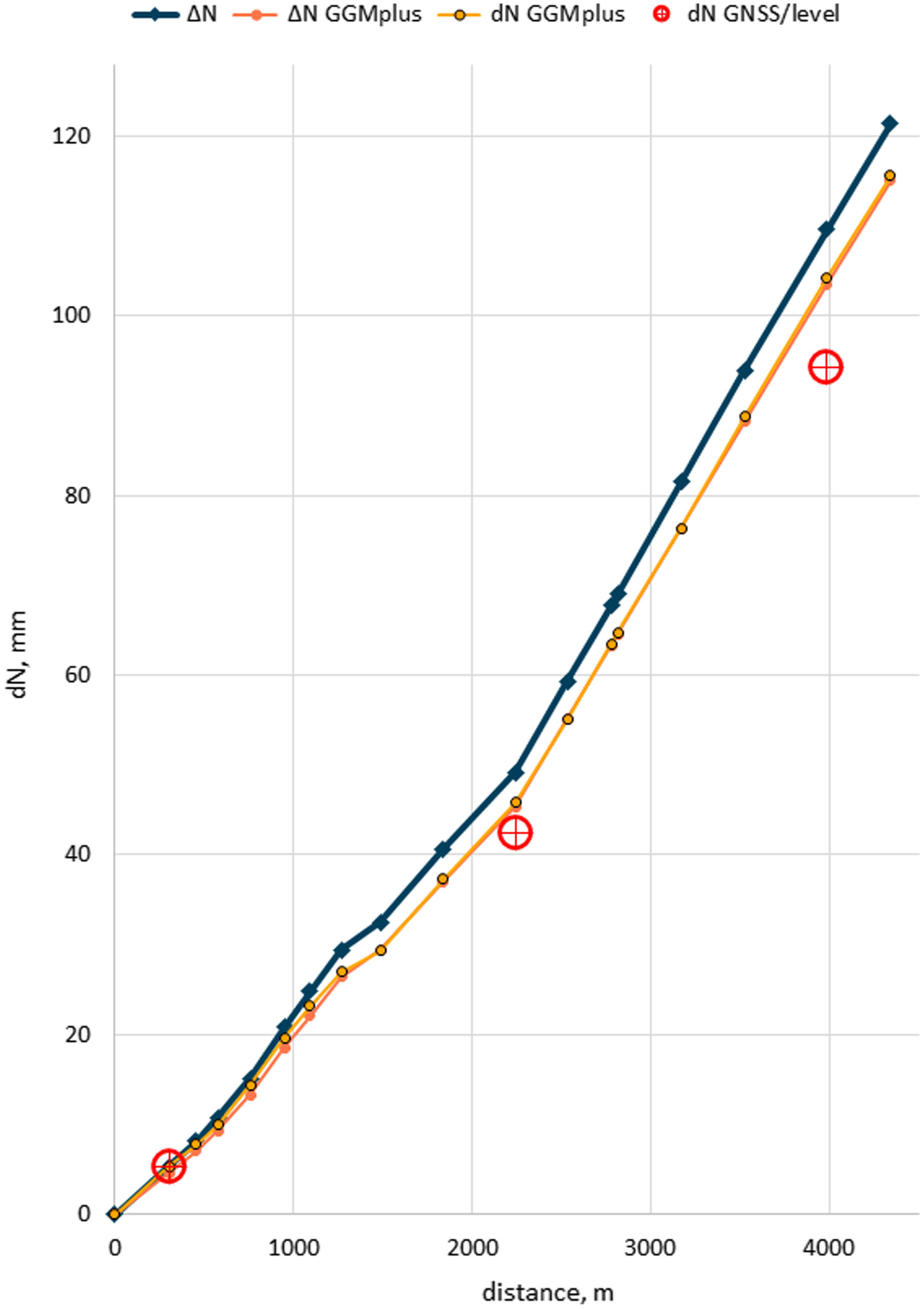
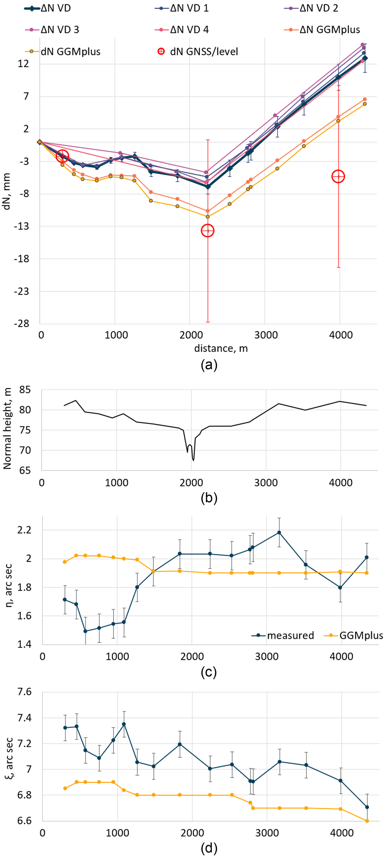
The results of the geoid undulations as a function of distance along the route are presented in Fig. 3. Fig. 4 shows the same dependency with an average trend of subtracted to highlight the details. To investigate the effect of increasing the distance between measurement points, the same calculations were performed by omitting every second (), two of three ( ), three of four (), and four of five () consecutive points. The results are shown in Fig. 4(a).
The same calculations were carried out for VD values from the GGMplus model (linear interpolation between model points was used to derive VD values for measurement points) and for geoid undulations directly from GGMplus (also interpolated). The difference for the northernmost leveling point (Point 1295 in the first-order leveling network) was assumed to be the same as that for the VD measurements at that point, so these points coincide on the graph. Figs. 4(c and d) also show the dependency of the VD component measurements and the interpolated GGMplus values on the distance along the traverse. Note that the GGMplus data have 1-mm granularity for geoid undulations and 0.1-arcsec granularity for VD values.
The data presented in Table 1 and Figs. 3 and 4 indicate the following:
•
Comparison of the extrapolated geoid undulation value obtained from VD measurements with the undulation value obtained as the difference between ellipsoidal height and the catalog value of normal height shows a difference of 15 mm over the 4.5-km traverse.
•
The curves for the GGMplus model closely resemble the curve for the extrapolated geoid undulation but gradually diverge from it by about . This divergence is most likely caused by the difference between the GGMplus model and the measured vertical deflection values [by 0.2–0.4 arcsec, as in Figs. 4(c and d)]. The slight difference between GGMplus curves is probably the result of not quite accurate interpolation and, possibly, some averaging of GGMplus values (VD data with 0.1-arcsec granularity).
•
Omitting measurement points leads to the loss of detail in the geoid undulation curve and to the curve’s progressive divergence from the initial curve.
•
The systematic differences between measured and GGMplus VD values for up to 0.5 arcsec [Figs. 4(c and d)] are possibly caused by under-representation of topography effects in the GGMplus data. There are two significant topographical features: a river valley up to 50 m deep located 5 km north of the traverse and a ravine up to 10 m deep crossing the trace slightly before the midpoint [Fig. 1 and the height profile of the trace in Fig. 4(b)]. The GGMplus topography component is based on SRTM data, which exhibit considerable error in places with steep terrain and dense vegetation (Farr et al. 2007; Hirt et al. 2013). Less than in reality, the SRTM model depth of these topographic features should produce the size and direction of the GGMplus VD model deviations from measurements [Figs. 4(c and d)].
Discussion
VD measurements inevitably contain errors directly influencing height transfer. As shown in Zariņš et al. (2018), the dispersion (RMS) of measured VD values is typically around 0.1 arcsec for a standard measurement session (up to one hour), and it may be reduced several times for longer or repeated measurements.
If the topography of the traverse is complicated and the distance between measurement points is too long, estimated VD values may not represent the entire extrapolation range and so serious extrapolation errors may occur. An example is shown in Fig. 4(a), where the curves represent height transfer with omitted measurement points. In such cases, either measurement points should be placed close enough or averaged values covering the entire topographical feature [e.g., the variant in Fig. 4(a)] should be used. This may cause serious problems in mountain regions.
Our research involved ellipsoidal height measurements by means of static GNSS measurement sessions lasting 6 to 7 hours and using a double-difference post-processing approach. The point height accuracy for such measurements might reach 5 mm for a 6-h session (Firuzabadì and King 2012). However, we considered the obtained ellipsoidal height accuracy of approximately 10 mm. Longer or repeated static GNSS sessions could have enhanced the accuracy of our measured ellipsoidal heights. However, limited time and financial resources prohibited longer measurements, such as 12- or 24-h static GNSS measurements or repeated 6-h static GNSS measurements. In our case, the ellipsoidal height accuracy of the initial point imposed a lower limit on the accuracy of the entire traverse extrapolation. This is generally a limiting factor for short traverses, where it dominates the accuracy of geoid extrapolation. Also, in our case it limited accurate comparison with the leveling network to a centimeter.
Finally, there are no reliable published estimates of the accuracy of Latvian first-order leveling network point heights. For the involved points, accuracy may vary from a few millimeters to a few centimeters. Given these circumstances, further work is needed, such as test leveling along the trace.
Conclusions
Extrapolation of geoid undulation along a traverse with measured or other known VD values can be used for accurate transfer of undulation changes and, in combination with GNSS ellipsoidal height measurements, for transfer of height above sea level.
The accuracy of geoid undulation transfer can be or better at a VD accuracy of about 0.1 arcsec and an average distance between measurement points of a few hundred meters. If the geoid surface is smooth, the distance between points can be greater, probably up to 1–2 km. In complicated topography (e.g., mountain regions), smaller distances between points may be needed and/or the choice of points should be based on topography feature impact analysis.
If lesser accuracy () suffices, a global geopotential model with high spatial resolution (e.g., GGMplus) can be used, possibly aided by some calibration of VD measurements. In any case, parallel calculations using geoid model data help to exclude gross data errors.
Combining VD measurements with GNSS measured ellipsoidal heights for normal height determination offers several advantages over geometrical leveling. Both VD and ellipsoidal height measurements can be obtained independently for intermediate points, allowing the use of old data in conjunction with new measurements. This method can be advantageous if long-distance profiles must be measured or if natural or administrative obstacles are encountered in a profile. GNSS measurements can be taken either simultaneously with VD measurements or sequentially, providing flexibility in measurement planning depending on weather conditions and equipment availability. Additionally, the distance between measurement points can be an order of magnitude greater than that obtained via geometrical leveling.
VD measurement process using DZC VESTA is fully automatic and requires only one operator, whereas geometrical leveling campaigns are highly demanding and require a team of qualified persons, increasing campaign costs. However, VD measurements can only be performed on clear nights, which can be challenging when planning measurements in areas with frequent cloud cover, although geometric leveling requires certain weather conditions as well. Therefore, the proposed method might offer a cheaper and more convenient alternative to classical geometrical leveling.
Data Availability Statement
All data, models, or code that support the findings of this study are available from the corresponding author upon reasonable request.
Acknowledgments
This research has been supported by European Regional Development Fund Post-Doctoral Research Aid, Project No. 1.1.1.2/VIAA/4/20/666: “Investigation on Accuracy Improvement of Automated Zenith Camera’s VESTA Deflection of Vertical Measurements.”
References
Celms, A., M. Kronbergs, V. Cintina, and V. Baumane. 2013. “Precision of Latvia leveling network nodal point height.” In Vol. 4 of Proc., 4th Int. Conf. Civil Engineering’13, Part I, Land Management and Geodesy, 310–317. Jelgava, Latvia: Latvia Univ. of Agriculture.
Farr, T. G., et al. 2007. “The shuttle radar topography mission.” Rev. Geophys. 45 (2): RG2004. https://doi.org/10.1029/2005RG000183.
Firuzabadì, D., and R. W. King. 2012. “GPS precision as a function of session duration and reference frame using multi-point software.” GPS Solutions 16 (2): 191–196. https://doi.org/10.1007/s10291-011-0218-8.
Guillaume, S., B. Bürki, S. Griffet, and H. M. Durand. 2012. “QDaedalus: Augmentation of total stations by CCD sensor for automated contactless high-precision metrology.” In Proc., FIG Working Week 2012. Rome: International Federation of Surveyors.
Hirt, C., S. Claessens, T. Fecher, M. Kuhn, R. Pail, and M. Rexer. 2013. “New ultrahigh-resolution picture of Earth’s gravity field.” Geophys. Res. Lett. 40 (16): 4279–4283. https://doi.org/10.1002/grl.50838.
Hirt, C., and J. Flury. 2008. “Astronomical-topographic levelling using high-precision astrogeodetic vertical deflections and digital terrain model data.” J. Geod. 82 (4–5): 231–248. https://doi.org/10.1007/s00190-007-0173-x.
Hirt, C., M. Schmitz, U. Feldmann-Westendorff, G. Wübbena, C. H. Jahn, and G. Seeber. 2011. “Mutual validation of GNSS height measurements and high-precision geometric-astronomical leveling.” GPS Solutions 15 (2): 149–159. https://doi.org/10.1007/s10291-010-0179-3.
Legal Acts of the Republic of Latvia. 2011. “Cabinet Regulation No. 879: Regulations regarding the geodetic reference system and the topographic map system.” Accessed December 8, 2022. https://likumi.lv/ta/en/en/id/239759.
LGIA (Latvian Geospatial Information Agency). n.d. “Latvian state geodetic network data base.” Accessed June 16, 2022. https://geodezija.lgia.gov.lv/VGT/index.php.
Morozova, K., R. Jäger, A. Zarins, J. Balodis, I. Varna, and G. Silabriedis. 2021. “Evaluation of quasi-geoid model based on astrogeodetic measurements: Case of Latvia.” J. Appl. Geod. 15 (4): 319–327. https://doi.org/10.1515/jag-2021-0030.
Schack, P., C. Hirt, M. Hauk, W. E. Featherstone, T. J. Lyon, and S. Guillaume. 2018. “A high-precision digital astrogeodetic traverse in an area of steep geoid gradients close to the coast of Perth, Western Australia.” J. Geod. 92 (10): 1143–1153. https://doi.org/10.1007/s00190-017-1107-x.
Smith, D. A., S. A. Holmes, X. Li, S. Guillaume, Y. M. Wang, B. Bürki, D. R. Roman, and T. M. Damiani. 2013. “Confirming regional 1 cm differential geoid accuracy from airborne gravimetry: The geoid slope validation survey of 2011.” J. Geod. 87 (10–12): 885–907. https://doi.org/10.1007/s00190-013-0653-0.
van Westrum, D., K. Ahlgren, C. Hirt, and S. Guillaume. 2021. “A geoid slope validation survey (2017) in the rugged terrain of Colorado, USA.” J. Geod. 95 (Jan): 1–9. https://doi.org/10.1007/s00190-020-01463-8.
Voigt, C., and H. Denker. 2014. “Validation of second-generation GOCE gravity field models by astrogeodetic vertical deflections in Germany.” In Proc., Earth on the Edge: Science for a Sustainable Planet: Proc., IAG General Assembly. Berlin: Springer.
Wang, Y. M., et al. 2017. “The geoid slope validation survey 2014 and GRAV-D airborne gravity enhanced geoid comparison results in Iowa.” J. Geod. 91 (10): 1261–1276. https://doi.org/10.1007/s00190-017-1022-1.
Zariņš, A., A. Rubans, and G. Silabriedis. 2018. “Performance analysis of Latvian zenith camera.” Geod. Cartogr. 44 (1): 1–5. https://doi.org/10.3846/gac.2018.876.
Zariņš, A., A. Rubans, and G. Silabriedis. 2016. “Digital zenith camera of the University of Latvia.” Geod. Cartogr. 42 (4): 129–135. https://doi.org/10.3846/20296991.2016.1268434.
Information & Authors
Information
Published In

Journal of Surveying Engineering
Volume 149 • Issue 4 • November 2023
Copyright
This work is made available under the terms of the Creative Commons Attribution 4.0 International license, https://creativecommons.org/licenses/by/4.0/.
History
Received: Dec 19, 2022
Accepted: Jul 4, 2023
Published online: Sep 8, 2023
Published in print: Nov 1, 2023
Discussion open until: Feb 8, 2024
Authors
Metrics & Citations
Metrics
Citations
Download citation
If you have the appropriate software installed, you can download article citation data to the citation manager of your choice. Simply select your manager software from the list below and click Download.