Shear Design of Strain-Hardening Fiber-Reinforced Concrete Beams
Publication: Journal of Structural Engineering
Volume 149, Issue 2
Abstract
Strain-hardening fiber-reinforced concrete (SH-FRC), such as ultrahigh-performance concrete (UHPC), offers sustained tensile capacities up to high values of postcracking strains and, consequently, delivers shear resistance through different mechanisms than conventional concrete. Existing shear design methods for conventional concrete beams include empirical approximations of the tensile resistance offered by the cracked concrete that do not apply to SH-FRC materials. This article presents a design formulation that predicts the shear capacity of SH-FRC beams in support of ongoing efforts to develop UHPC structural design guidance in the United States. The proposed model leverages foundational concepts from engineering mechanics, similar to the modified compression-field theory (MCFT) for conventional reinforced and prestressed concrete, while integrating relationships that address behaviors specific to SH-FRC. The model predicts shear stress versus shear strain behavior of a cracked SH-FRC membrane element, which is then used to model the web of a beam. Verified against experimental shear test results of I-shaped prestressed and non-prestressed beams with different material properties, beam geometries, axial strains, and transverse reinforcement ratios, the proposed shear design model is demonstrated to conservatively predict the shear capacity of SH-FRC beams. As such, this work constitutes a fundamental step in developing mechanics-based SH-FRC shear design guidance.
Introduction
The tensile ductility of strain-hardening fiber-reinforced concrete (SH-FRC), such as ultrahigh-performance concrete (UHPC), constitutes a key performance metric that distinguishes its behavior from that of conventional concrete. Reinforced with a high dosage of discontinuous steel fibers, typical UHPC-class materials exhibit tensile strength exceeding 7.0 MPa (1.0 ksi) sustained well into the postcracking stress–strain regime. This behavior is shown to contribute significantly to the shear capacity of beams because fibers transmit forces across diagonal cracks, thus supplementing or even replacing the transverse reinforcement in resisting shear forces (Voo et al. 2006; Voo and Foster 2008; Baby 2012; Kamal et al. 2014; Pourbaba et al. 2018; El-Helou and Graybeal 2019; Hemstapat et al. 2020). Recent experimental investigations on UHPC beams and panel elements showed that, given the high compressive strength of UHPC, the shear failure is often controlled by the tensile behavior rather than compressive failure (Voo et al. 2010; Baby et al. 2014; Ahmad et al. 2019; Yap 2020; El-Helou and Graybeal 2022b). Although the design provisions for the shear behavior of conventional concrete are well established (ACI 2019; AASHTO 2020), they are not suitable for UHPC because they do not account for the material’s improved mechanical performance, leading to inefficient designs and uneconomical structures. This lack of national design provisions and the relatively high cost of the material compared to conventional concrete have hindered UHPC’s large-scale application for structural members in the United States. However, when design principles suited for the distinctive material behavior of UHPC are used, reductions in traditional steel reinforcement, member dimensions, and self-weight of the structure can be realized. These features can provide financial benefits associated with the reduction in material usage, load demands, member depth, labor, construction time, equipment needs, and shipping and handling costs, along with potentially eliminating beam lines or intermediate supports.
This article presents an analytical model to describe the stress–strain behavior of a cracked SH-FRC membrane element subjected to shear and axial stresses. The model is based on the force equilibrium and strain compatibility equations established over a rectangular SH-FRC membrane element, similar to the modified compression-field theory (MCFT) developed for conventional concrete by Vecchio and Collins (1986), and integrates new constitutive relationships that address behaviors specific to SH-FRC. The analytical results of the shear model are compared to the experimental data obtained from tests on UHPC panels subjected to pure shear performed by Yap (2020). The model formulation for membrane elements is then used to predict the shear behavior of the web of beams and formulate a design method to predict the shear capacity of SH-FRC beams. The proposed design approach for SH-FRC beams parallels the derivations of the simplified MCFT (Bentz et al. 2006), which is currently implemented in the AASHTO Load and Resistance Factor Design Bridge Design Specifications (AASHTO LRFD BDS) (AASHTO 2020). The capability of the method to predict the shear capacity of prestressed and non-prestressed UHPC beams is validated against experimental test results obtained by El-Helou and Graybeal (2022b) and Baby et al. (2014).
UHPC-Class Materials
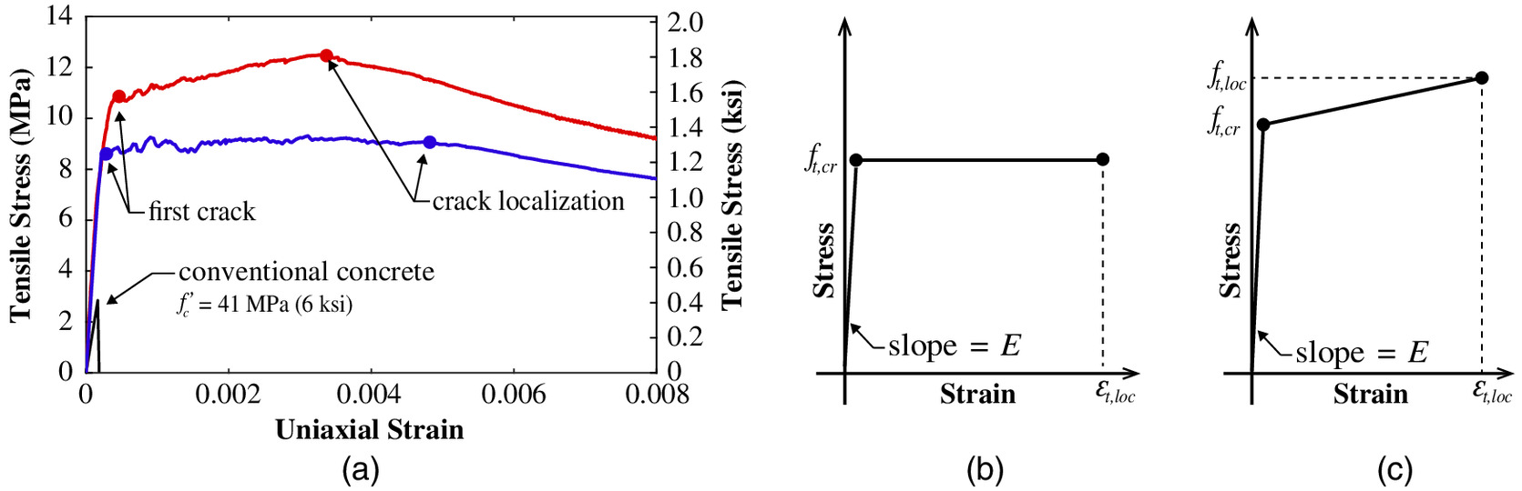
The shear model described in this study applies to SH-FRC materials, with an emphasis on UHPC materials exhibiting certain key performance characteristics. For the purpose of this work, UHPC is defined as a portland cement–based material composed of an optimized gradation of granular constituents, very low water-to-cementitious materials ratio, and high percentage of discontinuous internal steel fiber reinforcement. The mechanical properties include a minimum compressive strength of 124 MPa (18.0 ksi) and a minimum cracking strength of 5.0 MPa (0.73 ksi) that is sustained through a localization strain of at least 0.0025. The compressive properties are obtained from compression testing according to ASTM C1856 (ASTM 2017). The tensile characteristics are obtained from uniaxial tension testing according to AASHTO T397 (AASHTO 2022), which is based on the method developed by Graybeal and Baby (2013). In this test method, the stress–strain response of UHPC is obtained from a direct capture of the tensile load and associated strain applied over a known cross section and gage length during a fixed-end uniaxial displacement-controlled test. Fig. 1(a) shows examples of experimental stress–strain plots typical for the UHPC materials considered in this study. These trends can be separated into two classes of idealized tensile characteristic responses: (1) relatively constant postcracking stress with increasing strain, represented as an elastoplastic model shown in Fig. 1(b); and (2) strain hardening with continuous increase in postcracking stress, represented as a bilinear model shown in Fig. 1(c). In Figs. 1(b and c), is the modulus of elasticity, is the stress at the occurrence of the first crack, and and are the localization stress and corresponding strain at onset of softening, which is used as the endpoint of the idealized stress–strain curves. More information on determining these key tensile parameters from experimental direct tension results can be found in El-Helou et al. (2022) and Haber et al. (2018).
Existing Shear Design Models for UHPC
A few design recommendation documents using various design principles to predict the shear capacity of UHPC beams have been published in other countries. For instance, the French National Addition to the Eurocode 2 (AFNOR 2016), which provides rules for UHPC design, calculates the total shear capacity, , from the superposition of three resistance terms provided by the UHPC: , the transverse reinforcement, , and the fibers, , as shown in
(1)
Three empirical relationships for are recommended depending on whether the section is prestressed, non-prestressed with transverse reinforcement, or non-prestressed without transverse reinforcement. These formulae depend on the UHPC’s compressive strength, effective shear depth (defined as the lever arm of internal forces corresponding to the applied bending moment), axial force in the cross section, width of the web, and height of the section.
The fiber contribution to the shear strength, , is defined by Eq. (2), in which is the mean value of the postcracking strength perpendicular to the shear crack of inclination, ; is the width of the web; and is the effective shear depth. The value of is obtained from uniaxial tensile stress–strain results derived from a specified inverse analysis of the results of a flexural prism test, and includes a partial safety factor and an orientation factor. The inclination angle of the principal compression stress with respect to the longitudinal axis, , is determined from an elastic stress transformation evaluated at the center of gravity of the beam at the expected force demand at the ultimate limit state. The value of is required to be equal to or greater than 30°. The French shear design methodology for beams concludes by requiring that the stress in the compression field be lower than the compressive resistance limit and that the flexural reinforcement be able to accommodate the increase in tensile force due to the applied shear force
(2)
In Switzerland, the recommendations for UHPC structural design (SIA 2016) include one term to represent the UHPC’s contribution, , instead of a UHPC term and a fiber term, as recommended by the French specification document. The total capacity of the beam, , is calculated as
(3)
is calculated according to Eq. (4), in which and are the uniaxial elastic (cracking) tensile strength and ultimate tensile strength of the UHPC, respectively. The tensile parameters are determined according to a direct tension method or calculated from inverse analysis of the results of a flexural prism test. Here, is the shear force contribution of the transverse steel reinforcement, as follows:
(4)
The Swiss recommendation specifies a minimum inclination angle, , of 30° for most cases, 25° if the web is subjected to considerable compressive stresses, and 40° if the web is subjected to considerable tensile stresses or plastic deformations of the flanges. Similar to the French specifications, the Swiss recommendations include a limit on the stresses in the compression field and on the tensile stress in the longitudinal reinforcement.
The shear design recommendations in Canada are published in Annex A8.1 of the Canadian Highway Bridge Design Code (CSA 2019) and are applicable only for tension-softening fiber-reinforced concrete (TS-FRC). A model for SH-FRC, such as UHPC, referred to as tension-hardening fiber-reinforced concrete in CSA S6:19 (CSA 2019), is not provided. The recommendation for TS-FRC is based on the work of Foster and Agarwal (2018), who proposed a new equation to the existing MCFT model to account for the fiber contribution to the shear resistance. The factored shear resistance, , is defined in Eq. (5), in which is the concrete contribution (without fibers), is the transverse steel contribution (using the same equations as for conventional concrete), is the fiber contribution term defined in Eq. (6), and is the component of the prestress force in the direction of the shear force.
(5)
(6)
In Eq. (6), = fiber orientation factor; = material resistance factor applied to the postcracking tensile strength; = postcracking tensile strength derived as function of crack width; = web width; and = effective shear depth.
Although the existing models for SH-FRC can predict aspects of shear behavior, they rely on empirical approximations for the critical shear angle, do not correlate shear capacity as a function of the postcracking performance characteristics of SH-FRC, and assume that transverse steel reinforcement, when included, will always yield at shear failure. Based on these observations, there is a need to develop a mechanics-based shear design model that accounts for the postcracking strain capacity of SH-FRC and captures its influence on the critical shear angle and the transverse steel stress at failure. The model proposed in this article addresses this need.
Description of Shear Model
The proposed model predicts the relationship between the average axial and shear stresses as a function of the average axial and shear strains of a cracked SH-FRC rectangular membrane element. The membrane element is assumed to mimic a portion of a structure with uniform thickness, such as the web of a beam, shear walls, shell structures, and so forth. The model formulation is founded on the principles of strain compatibility, in which stresses over strained sections are calculated based on known mechanical stress–strain models and summed to establish equilibrium. The proposed derivations parallel the approach followed in the MCFT developed by Vecchio and Collins (1986) for conventional reinforced concrete while engaging new material constitutive relationships, including pre- and postcracking tensile response, to complete the model for SH-FRC.
Modified Compression-Field Theory
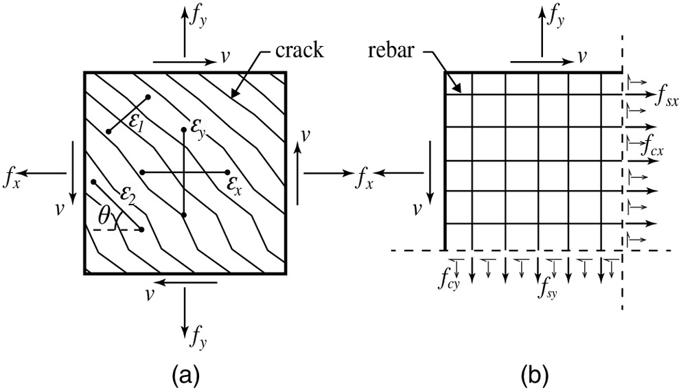
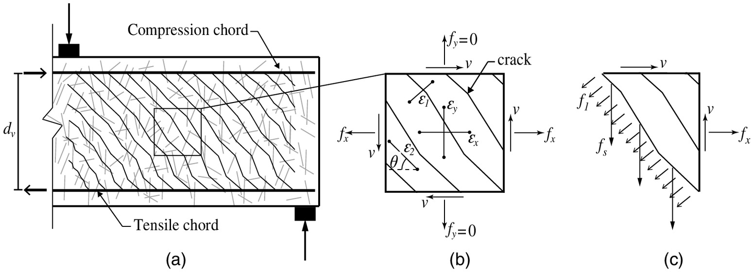
The MCFT was developed by observing the response of reinforced concrete panel tests loaded in pure shear or in shear combined with axial stresses. These tests provided insight into the shear behavior of conventional concrete, and supported efforts to develop a rational methodology for shear design. Consider a cracked concrete membrane element with uniform thickness and reinforced with an orthogonal grid of uniformly distributed steel bars, as shown in Fig. 2. The longitudinal and transverse axes of the element, denoted by the -axis and -axis, respectively, are selected to align with the reinforcement directions. The panel is subjected to three in-plane uniform axial and shear stresses—, , and —which can be related to their respective strains, , , and . The principal tensile and compressive stresses are denoted by and and are related to their corresponding principal strains, and . The angle between the principal compressive direction and the -axis is denoted by . In deriving the MCFT equations, it is assumed that (1) the principal stress and strain directions coincide, (2) the element stresses and strains can be considered in terms of their average values because they are taken over distances that include several cracks, (3) each strain state corresponds to only one stress state, and (4) the steel and concrete are perfectly bonded. Tensile stresses and strains are taken as positive values, whereas compressive stresses and strains are taken as negative values.
Compatibility Equations
By maintaining a perfect bond between the steel and concrete, Vecchio and Collins (1986) used Mohr’s circle of strains to derive the strain compatibility relationships shown in Eqs. (7)–(9) to link the applied average strains, , , and , to the principal average strains, and , and the inclination angle, , as follows:
(7)
(8)
(9)
Equilibrium Equations
To satisfy equilibrium, the MCFT resolves the forces applied on the membrane element into stress components resisted by the concrete and steel bars in the longitudinal and transverse directions. For instance, and , where and are the concrete stresses, and are the steel reinforcement ratios, and and are the stresses in the longitudinal and transverse directions, as shown in Fig. 2(b). Using Mohr’s circle for the concrete stresses, the equilibrium relationships described in Eqs. (10)–(12) are derived in terms of average stresses, as follows:
(10)
(11)
(12)
Material Constitutive Relationships for Conventional Concrete and Reinforcing Steel
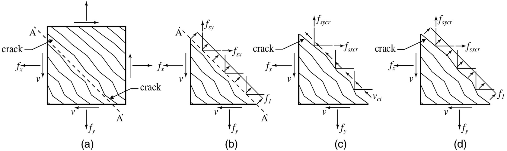
To calculate axial and shear stresses (, , and ) as a function of their respective strains (, , and ), it is necessary to know the biaxial relationships between the concrete principal stresses ( and ) and strains ( and ) and between the uniaxial stresses in the reinforcing steel ( and ) as a function of the axial strains ( and ). For reinforced concrete, the compressive and tensile constitutive relationships were experimentally established by Vecchio and Collins (1986) based on 30 reinforced concrete elements tested under biaxial stresses in a complex shell element testing frame. These tests revealed that, in a reinforced concrete element subjected to high principal tensile strains, the compressed concrete is weaker and softer than concrete in a standard cylinder compression test. They also showed that tensile stresses, , exist in the concrete between cracks even after extensive diagonal cracking, and the stresses decrease with increasing values of principal tensile strain, . The MCFT principal stress–strain relationships for conventional concrete can be found in Table 1. A free-body diagram of the principal and steel stresses in between the diagonal cracks of a membrane element is shown in Figs. 3(a and b).
| Description | Governing equations |
|---|---|
| Principal stress–strain | |
| Equilibrium for stresses at a crack | |
| Shear stress on a crack | |
| Crack width | |
Source: Data from Vecchio and Collins (1986).
Note: Tensile stresses and strains are taken as positive values, whereas compressive stresses and strains are taken as negative values.
The constitutive relationships for the reinforcing steel bars are assumed to follow the typical elastic-plastic uniaxial relationships shown in Eqs. (13) and (14), in which is the modulus of elasticity of reinforcing steel, and and are the yield stress of the rebars in the and directions, respectively.
(13)
(14)
Equilibrium Equation for Stresses at Cracks in Conventional Concrete
The MCFT equilibrium and compatibility equations shown in Eqs. (7)–(12) describe the shear behavior of a membrane element in terms of average values of stresses and strains. In conventional concrete, the transfer of loads across cracks is intrinsically linked to the variations that exist between the average and local stresses in the concrete and steel in the vicinity of cracks. Figs. 3(b and c) show the free-body diagrams of the average stresses for conventional concrete in between the diagonal cracks and the stresses at the crack surfaces of a membrane element. According to Vecchio and Collins (1986), these variations are attributed to (1) the principal tensile stresses in the concrete being higher than average midway between the diagonal cracks but equal to zero at the crack interface, (2) the tensile stresses in the reinforcement being higher than average at cracks and lower than average midway between cracks, and (3) the existence of an average shear stress at the crack interface, , attributed to the aggregate interlock of rough shear cracks.
To ensure that the average stresses between cracks in the concrete, , and reinforcing steel, and [Fig. 3(b)], are statically equivalent to the local stresses at cracks in the reinforcing steel, and , combined with the shear stress, [Fig. 3(c)], the equilibrium equations shown in Table 1 are derived and enforced in the MCFT formulation. The shear stress at cracks, , is calculated as a function of the opening of cracks, , and the maximum size of the aggregate in the concrete mix, , based on the experimental work of Walraven (1981), as shown in Table 1. The crack opening, , is estimated as a function of the crack angle, , and the spacing of cracks in the and directions, and , respectively.
Finally, the solution of the stresses , , and of a steel-reinforced conventional concrete cracked membrane element subjected to known values of strain (, , and ) can be found by iteratively solving a system of equations. The equations govern compatibility and equilibrium [Eqs. (7)–(12)], the mechanical behavior of reinforcing steel [Eqs. (13) and (14)], and the mechanical behavior and equilibrium at cracks pertaining to conventional concrete (Table 1).
Proposed Model for SH-FRC Membrane Element
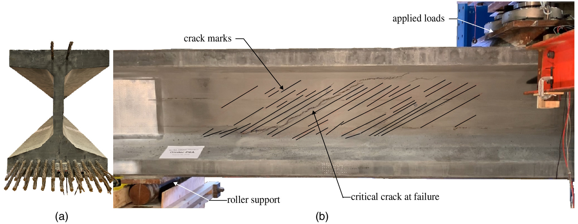
The proposed model for SH-FRC adopts the free-body diagram of Fig. 2, the compatibility and equilibrium equations [Eqs. (7)–(12)], and the uniaxial stress–strain relationships for the reinforcing steel [Eqs. (13) and (14)] for the analysis of a cracked membrane element. These compatibility and equilibrium derivations are considered applicable for SH-FRC because experimental observations of large-scale UHPC beam shear tests showed the material’s ability to develop multiple diagonal, parallel, and closely spaced cracks even when no transverse steel reinforcement is present in the web of the girder (Graybeal 2006a; Voo et al. 2010; Baby et al. 2014; El-Helou and Graybeal 2022b). Moreover, these tests showed that shear failure occurred when deformation began to localize into a single crack after the girder’s web had already become saturated with cracks. Fig. 4 shows the crack pattern after failure of a UHPC prestressed girder tested in shear without transverse steel reinforcement. The girder in Fig. 4 had web width of 76.2 mm (3 in.), height of 889 mm (35 in.), span of 9.75 m (32 ft), shear span-to-depth () ratio of 3.6, and shear capacity of 1,266 kN (285 kips). This level of resistance to shear forces is attributed to UHPC’s enhanced mechanical behavior, particularly its postcracking tensile capacity, compared to conventional concrete. Therefore, to develop a strain compatibility-based shear model predictive of SH-FRC behavior, it is necessary to rederive portions of the MCFT formulation that are calibrated to conventional concrete behaviors (i.e., the material constitutive relationships and equilibrium conditions at cracks) with constitutive relationships relevant to SH-FRC.
Material Constitutive Relationships for SH-FRC
The uniaxial stress–strain relationships in compression and tension for SH-FRC materials, such as UHPC, have been well established (Graybeal 2006b; Russel and Graybeal 2013; Haber et al. 2018; El-Helou et al. 2022). However, modifications should be incorporated to account for biaxial strain states, particularly in compression, because compression principal stress fields are often accompanied by high principal tensile strain fields during shear loading. In advance of anticipated future research on biaxial stress states on UHPC membrane elements, reduction factors, and , are applied on each of the modulus of elasticity, , and compressive strength, , to account for these effects. These reduction factor would ideally be a function of the applied principal tensile strain, , and would lead to a predictive value of the secant stiffness and compressive strength of a cracked SH-FRC membrane subjected to compression loading. El-Helou and Graybeal (2022b) found that a value of 0.5 for both and reasonably estimates the secant stiffness at peak shear stress in the web of UHPC beams and leads to conservative predictions of the compressive strength at shear failure. The proposed constitutive relationship of compressed SH-FRC is defined in Eq. (15), where is the uniaxial strain corresponding to the compressive strength, . Note that compressive stresses and strains are taken as negative quantities.
(15)
For SH-FRC subjected to uniaxial tensile stresses, the fibers embedded in the matrix enable SH-FRC to maintain the tensile stress at or above the cracking stress at high tensile strain capacities, typically up to strain values between 0.003 and 0.008 for UHPC-class materials (El-Helou et al. 2022). Similar to conventional concrete, when SH-FRC is subjected to shear stresses, the formation of diagonal cracks results in principal tensile strains that are generally greater than the principal compressive strains because the average tensile strains of the membrane element encompass several cracks. Experimental tests on large-scale UHPC girders performed at the Federal Highway Administration (FHWA) Turner-Fairbank Highway Research Center (TFHRC) (El-Helou and Graybeal 2022b) and pure shear tests on UHPC panel elements performed at the University of Toronto (Yap 2020) showed that the principal tensile strain at failure was more than 2.5 times greater than the principal compressive strain. Thus, it is assumed that implementing the uniaxial stress–strain relationship shown in Fig. 1 will not result in significant loss of accuracy. The proposed tensile constitutive relationship for UHPC can be written aswhere is taken as the cracking strain. Note that tensile stresses and strains are taken as positive quantities.
(16a)
(16b)
Equilibrium Equations for Stresses at Cracks in SH-FRC
Similar to the MCFT, the stress and strain compatibility equations in the proposed formulation for a cracked UHPC membrane element are written in terms of average stresses and strains. Therefore, the combined stresses in the transverse steel and SH-FRC in between diagonal cracks should be statically equivalent to the stresses in the same materials at the crack interfaces.
In this proposal, the local variation between the average and local stresses in SH-FRC before the localization of cracks () is assumed to be negligible for two reasons. First, the postcracking tensile stress is equal to or greater than the cracking stress; thus, the local principal tensile stress at a crack is equal to the average tensile stress in SH-FRC between cracks, as shown in the free-body diagrams of Figs. 3(b and d). Second, the shear stress along the crack planes, , is not thought to significantly contribute to the response of the membrane before crack localization () where noticeable slippage along the principal crack starts to occur, as shown in Fig. 4; is set equal to zero because the fibers transmit forces across cracks and maintain extremely tight crack width before crack localization. This interpretation is in line with the observation of Yamada and Krauthammer (1997), who concluded that the application of strain compatibility in MCFT is equivalent to the assumption that slip is not allowed at crack surfaces. Moreover, after crack localization, shear stresses due to aggregate interlock are expected to be minimal along the principal crack because SH-FRC materials usually do not contain coarse granular components in the mix.
The aforementioned assumptions presume that the local and average stresses in the steel bars are equal (i.e., and ) before crack localization (). In the experimental beam shear tests performed by the authors and reported in El-Helou and Graybeal (2022b), the average transverse strains measured at midheight of the web in the four instrumented bars [Bars 12, 14, 16, and 18 in Fig. 4 of El-Helou and Graybeal (2022b)] located within the middle third of the shear span were 932, 1,668, 1,960 microstrain, with standard deviations of 169, 256, and 256 microstrain, when the applied shear load was 60%, 75%, and 80% of the shear failure load, respectively. (Note that four out of the eight bars reinforcing the middle third of the shear span were instrumented). Given the relatively small standard deviation of individual strains in the bars along the shear span, and assuming that some of the diagonal cracks crossed the bars at midheight while others did not, this observation suggests that the local and average stresses in the steel bars can be reasonably assumed equal.
Solution Procedure
The proposed model aims to predict the applied axial and shear stresses (, , ) given the strains (, , ) in the SH-FRC membrane element by simultaneously solving the set of 10 equations listed in Eqs. (7)–(16). The uniaxial material parameters of the SH-FRC and reinforcing steel are used as input parameters. These include the modulus of elasticity, , compressive strength, , strain at compressive strength, , reduction factor accounting for biaxial effects, , tensile cracking stress, , and localization stress and strain, and , of the SH-FRC, as well as the modulus of elasticity and yield strength of the reinforcing steel, , , and .
Two possible shear failure modes can be identified. The first mode occurs when the principal tensile strains localize into a single crack (). After localization, the fibers bridging the critical crack start to pull out of the matrix, causing the tensile resistance in the SH-FRC to decrease and prompting a rapid increase in the width of a single crack. The model does not account for any postlocalization capacity of the SH-FRC element. This failure mode can occur before yielding of transverse steel reinforcement (when the element average axial strain is less than the yielding strain of reinforcing steel in or directions), depending on the SH-FRC tensile strain capacity and on the yield stress, yield strain, and amount of steel reinforcement. A second failure mode occurs at the crushing of the SH-FRC in the compression field when the principal compressive stress reaches the biaxial stress limit, . This failure mode might be expected to occur when the SH-FRC element is reinforced with a proportionally large amount of transverse steel.
Analysis of UHPC Panels Tested in Pure Shear
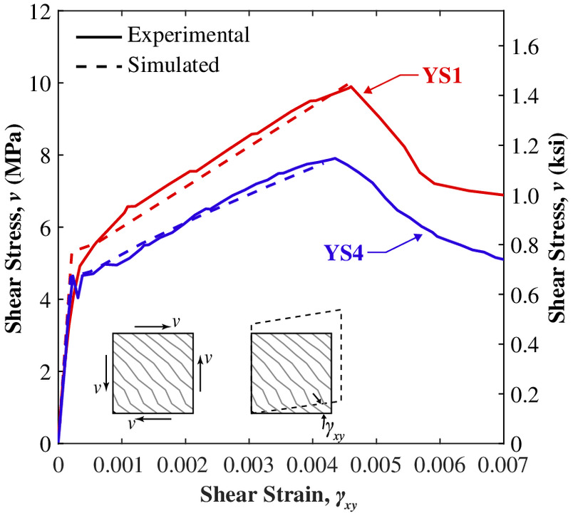
The capability of the membrane element model to simulate shear behavior was demonstrated herein by comparing the analytical results to the experimental data of four UHPC panels tested in pure shear in a shell element tester at the University of Toronto (Yap 2020). The UHPC panels contained the same 2% volume fraction of steel hooked-end and straight fibers. They had a nominal width and length of 1,626 mm (64.0 in.) and a thickness of 200 mm (7.9 in.), and were reinforced with conventional steel bars with different reinforcement ratios in the longitudinal and transverse directions.
Because the membrane element was subjected to pure shear (), the model equations can be simultaneously solved to predict the applied shear stress, , and strains, , , and , by selecting a range of possible values for . In analytically modeling the panel tests of Yap (2020), the input parameters for the steel bars ( and ) and compressed UHPC ( and ) were taken as equal to the reported average values obtained from material characterization tests performed on companion specimens. The reduction factors accounting for biaxial effects, and , were set equal to 0.5 during the portion of the behavior after cracking of the UHPC () for all panels. In the absence of uniaxial tensile parameters reported from appropriate direct tension test methods on companion specimens, the reported principal tensile stress and strain values measured during the tests at the occurrence of the first shear crack and peak load were used as input parameters for the tensile constitutive relationships (, , and ). By using these parameters, the analysis presented herein serves to demonstrate the appropriateness of the proposed modeling framework, not the individual tensile parameters used as inputs. It should be noted that Yap (2020) reported the tensile parameters obtained from an inverse analysis on the results of flexural prism tests companion to each panel except one panel (i.e., YS5), in which direct tension tests were carried out on dog-bone–shaped specimens in lieu of flexural prisms. The reported tensile parameters from prism tests were not used in the shear simulations because these values depend on the assumptions used in the inverse analysis technique, which has been shown to result in stress and strain values greater than those obtained from a direct tension test (Baby et al. 2012; Yap 2020). Also, results from the direct tension tests were not used because the tensile strains were not measured over a gauge length with a uniform strain field. The input parameters used in each panel simulation can be found in Yap (2020).
The trends of the simulated prepeak shear stress, , versus shear strain, , of two of the four panels are plotted atop their corresponding experimental data in Fig. 5 (with the unloading and reloading cycles omitted for clarity) to demonstrate the capability of the model to capture the overall shear behavior of UHPC panels. The simulated-to-experimental peak shear stress ratio for all four simulated panels ranged between 0.98 and 1.01, providing yet another verification that the proposed model can capture UHPC shear stress capacity when appropriate values of the uniaxial tensile properties are used as input parameters. Of note, the shear failures of all the panels corresponded to the first mode in which the peak shear stress occurred at the peak principal tensile stress. In addition, for the membrane element reinforced in both directions (i.e., YS1), the reported average strains along the -direction, , were lower than the yield strain of the steel bars in the same direction.
The experimental program of Yap (2020) included an additional panel not containing any conventional steel reinforcement. This panel was not incorporated in the simulation work in the current study because it failed at the onset of cracking and did not exhibit any postcracking strain capacity. This result may indicate that the material tested did not exhibit a strain-hardening behavior under direct tension (which is outside the scope of the proposed model). Additional experimental tests on unreinforced UHPC panels are required to assess the behavior. However, the current formulation is recommended for use only in structures in which at least one of the axial directions contains discrete steel reinforcement. In beam design, the proposed formulation is applicable for beams with unreinforced or reinforced webs only when steel flexural reinforcements are included along the longitudinal direction to resist flexural tensile loads, as recommended by El-Helou and Graybeal (2022a).
Design Approach for Beam Shear
Similar to the MCFT for conventional concrete, the most accurate approach for SH-FRC beam shear analysis would be to incorporate the proposed material model to represent elements of the beam discretized into cross-sectional layers (Vecchio and Collins 1988) or into an array of biaxial membrane elements (Vecchio 1989). However, design formulations commonly use simplifications that enable the predictive model to be codified. This study derived a UHPC model for beams using a simplified approach, similar to the one adopted for the simplified MCFT (SMCFT) derived by Bentz et al. (2006) and incorporated into the AASHTO LRFD BDS (AASHTO 2020). The approach predicts the shear capacity of the beam section using one membrane element located within the web of the beam, as shown in Figs. 6(a and b), assuming that shear stress is constant along the effective shear depth of the beam, , as defined in AASHTO LRFD BDS (AASHTO 2020). To simplify the presentation of the derivations, the beam’s shear reinforcement bars are positioned to align with the vertical direction (-direction) and the prestressing force is assumed to align with the longitudinal direction (-direction), as is the case, for example, with a straight tendon profile.
Following the assumptions adopted in the SMCFT (Bentz et al. 2006) and because the membrane element is used to model an area away from regions of the beam directly under concentrated loads, as shown in Figs. 6(a and b), the clamping stresses are assumed to be negligibly small (). If the beam is reinforced with only vertical steel bars (i.e., , , and ), Eq. (11) can be rearranged to obtain the shear stress in the beam aswhere is the transverse steel reinforcement ratio; = axial stress in the transverse steel; = area of transverse steel reinforcement within a distance in the longitudinal direction; and = minimum thickness of the beam’s web. Eq. (11) can also be derived from the free-body diagram of Fig. 6(c) by summing forces in the -direction. The nominal shear capacity of the beam, , can be calculated by multiplying the terms of Eq. (17) by the cross-sectional area contributing to the shear resistance, , and by setting equal to the UHPC localization stress, , which can be written asin whichand
(17)
(18)
(19)
(20)
Determination of Crack Inclination Angle
Refined Method
The next step in the design process is to determine the inclination angle of the critical diagonal crack, , as a function of the applied axial strain on the element, . Such a relationship can be derived by first combining the compatibility relationships of Eqs. (7) and (8) to give
(21)
Similarly, by combining and rearranging the equilibrium relationships of Eqs. (12) and (17), the following relationship between the SH-FRC principal tensile (positive quantity) and compressive stresses (negative quantity) can be derived as
(22)
Assuming that the compression behavior in the SH-FRC remains elastic at shear failure, Eq. (15) can be written as
(23)
Combining Eqs. (21)–(23) and taking and , the inclination angle, , at shear failure can be obtained as a function of the axial strain, , by solving the following equation:
(24)
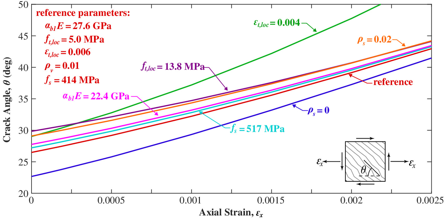
Given the material parameters of UHPC (, , , and ) and the steel reinforcement ratio in the web, , the crack inclination angle can be obtained by numerically solving Eq. (24) at a specified value of and an assumed value of . The average stress in the steel bars, , is usually equal to the yield stress, , at shear failure. In general, in a beam composed of a UHPC product exhibiting low values of localization strain (i.e., ) and reinforced with high-strength steel bars (e.g., or 75 ksi) at high values of (i.e., ), shear failure may occur before the yielding of the bars. In this case, Eq. (24) can be solved by an iterative procedure to determine the inclination angle, , and the average stress, , in steel at a specific value of . Fig. 7 illustrates the relationship between the crack angle, , and axial strain, , for a reference UHPC element with (4,000 ksi), (0.73 ksi), , (60 ksi), (29,000 ksi) and , as well as with varying values of , , , , and . As shown in Fig. 7, the critical shear crack angle, , increases with increasing values of , , , and , and with decreasing values of and .
Simplified Approach
Although Eq. (24) can be solved through an iterative procedure, it cannot be easily used for preliminary calculations of the shear capacity of UHPC beams, and the user cannot easily intuit the influence of each material and design parameter on the crack angle. Such considerations may be important for owners and designers in the early stages of a project because this preliminary design can help assess the project’s viability and provide an indication of the required material performance characteristics. Therefore, a simplified approach is discussed in this section to assist designers in determining the crack angle at a known value of as a function of the UHPC material parameters that have a significant effect on the shear capacity.
Considering the shear angle equation [Eq. (24)] and the parametric study results shown in Fig. 7, it can be inferred that the localization strain, , has the highest overall effect on the value of , followed by the steel reinforcement ratio, . Variations in the localization stress, , the secant compression stiffness of cracked UHPC, , and the stress in the steel, , have much less effect on the shear angle. Given that increases in and decreases in would increase , resolving Eq. (24) with an upper limit for of 12.4 MPa (1.80 ksi) and a lower limit for of 22.5 GPa (3,250 ksi), where (6,500 ksi) and , would result in conservative estimates of the shear angle. These limits are selected based on material characterization studies on commercially available UHPC products (El-Helou et al. 2022) and are in line with international recommendations (AFNOR 2016; SIA 2016). Therefore, in lieu of Eq. (24), Table 2 can be used to obtain estimates of the critical crack angle, , for UHPC beams without transverse reinforcement. In Table 2, angle values for are not included because the UHPC in the tensile flange of the beam would likely have localized, prompting a flexural failure.
| 27.9 | 27.3 | 26.5 | 25.7 | 25.1 | 24.5 | 24.0 | |
| 30.8 | 30.0 | 28.7 | 27.7 | 26.8 | 26.1 | 25.5 | |
| 34.5 | 33.2 | 31.4 | 30.0 | 28.9 | 27.9 | 27.2 | |
| 39.2 | 37.3 | 34.6 | 32.7 | 31.2 | 30.0 | 29.0 | |
| 45.4 | 42.4 | 38.4 | 35.7 | 33.8 | 32.3 | 31.0 | |
| — | 48.6 | 42.8 | 39.2 | 36.7 | 34.8 | 33.2 | |
| — | — | 47.9 | 43.1 | 39.9 | 37.5 | 35.6 | |
| — | — | — | 47.5 | 43.4 | 40.4 | 38.2 | |
| — | — | — | — | 47.1 | 43.5 | 40.9 | |
| — | — | — | — | — | 46.9 | 43.7 | |
| — | — | — | — | — | — | 46.7 | |
For UHPC beams reinforced with conventional steel in the transverse direction, an increase in the steel stress at failure, , would increase the value of , according to Eq. (24). Therefore, a conservative estimate of the values of can be obtained by solving Eq. (24) with an upper limit for possible values of , set at a stress of 517 MPa (75 ksi), as shown in Table 3 for a beam with a steel reinforcement ratio = 0.01. As previously discussed, the shear failure can occur before the average yielding of the transverse bars, and these cases are identified in Table 3 by providing an upper limit of the usable stress in the steel. Nevertheless, the steel stress used to calculate [Eq. (20)] should not be greater than the yielding stress, , of the transverse reinforcing bars in the beam. Moreover, Table 3 can be used to provide a conservative estimate of for a beam with transverse steel reinforcement ratio, , lower than 0.01. Similar tables can be developed for higher values of .
| Parameter | ||||||||
|---|---|---|---|---|---|---|---|---|
| (deg) | 29.9 | 29.8 | 29.5 | 28.8 | 28.1 | 27.4 | 26.8 | |
| (MPa) | ||||||||
| (deg) | 32.7 | 32.3 | 31.6 | 30.8 | 29.8 | 28.9 | 28.2 | |
| (MPa) | ||||||||
| (deg) | 36.2 | 35.3 | 34.1 | 32.9 | 31.7 | 30.7 | 29.8 | |
| (MPa) | ||||||||
| (deg) | 40.6 | 39.1 | 36.9 | 35.4 | 33.9 | 32.6 | 31.5 | |
| (MPa) | ||||||||
| (deg) | 46.4 | 43.7 | 40.3 | 38.2 | 36.3 | 34.7 | 33.4 | |
| (MPa) | ||||||||
| (deg) | — | 49.5 | 44.3 | 41.3 | 38.9 | 37.0 | 35.4 | |
| (MPa) | — | |||||||
| (deg) | — | — | 48.9 | 44.7 | 41.8 | 39.5 | 37.6 | |
| (MPa) | — | — | ||||||
| (deg) | — | — | — | 48.6 | 45.1 | 42.2 | 39.9 | |
| (MPa) | — | — | — | |||||
| (deg) | — | — | — | — | 48.3 | 45.0 | 42.4 | |
| (MPa) | — | — | — | — | ||||
| (deg) | — | — | — | — | — | 48.1 | 45.0 | |
| (MPa) | — | — | — | — | — | |||
| (deg) | — | — | — | — | — | — | 47.8 | |
| (MPa) | — | — | — | — | — | — | ||
Note: .
Crushing of Compression Strut and Maximum Shear Strength
The shear strength derived according to Eqs. (18)–(20) assumes that the compressed UHPC follows a linearly elastic relationship with the principal strain, , and that the principal compression stress, , is less than . This assumption can be verified after the determination of and (if applicable) by using Eq. (22) with to obtain the principal compressive stress at failure, , as follows:
(25)
In reinforced concrete design, it is customary to perform a check on the crushing of the compression strut by comparing the calculated shear value to the maximum shear stress, , at which crushing occurs. Such a calculation can also be derived for UHPC by following a similar derivation procedure as that implemented in the SMCFT (Bentz et al. 2006). However, it will be necessary to make a number of assumptions about the expected strain states of the membrane element at crushing. For the compressed UHPC to crush, the principal compressive strain, , must be equal to , generally taken as . According to the compatibility relationship of Eq. (8) with , this compression failure is unlikely to occur for low values of localization strain () in which the failure is dominated by the tensile behavior of UHPC. For high values of , the value of is likely greater than the yielding strain of steel and can be taken as 0.002. If were also equal to 0.002 at failure, it can be deduced from Eqs. (7) and (12) that the maximum shear stress, , for UHPC will be approximately , which is identical to the value estimated for conventional concrete (Bentz et al. 2006; AASHTO 2020). In calculating , and were taken equal to 0.5 and was conservatively taken as equal to zero.
Determination of Axial Strain in Beam Web
The inclination angle of the critical crack [Eq. (24)] depends on the axial strain in the web of the beam, , which can be taken as half of the strain in the section at the centroid of the tension reinforcement, , as in AASHTO LRFD BDS (AASHTO 2020). In lieu of more detailed procedures, the approximate equation for , originally proposed by Collins et al. (1996), was adopted herein with a proposed modification to account for the tensile stresses of UHPC contributing to the resistance of flexural loads, as shown in Eq. (26). This equation accounts for the effects of factored flexural moment, , shear force, , axial force, , the prestress force , and the UHPC tensile force contributing to the flexural resistance, (ignoring the postcracking increases in stress when applicable), in which is the area of prestressing steel on the flexural tension side of the beam; is the stress in the strands calculated by multiplying the modulus of elasticity of the prestressing strands by the locked-in difference in strain between the concrete and strands [typically taken as for normal levels of prestressing, where is the specified ultimate stress of the prestressing steel (AASHTO 2020)]; is the area of UHPC subjected to flexural tensile stresses not to exceed the area within half of the section’s height on the flexural tensile side of the beam; is the area of non-prestressed steel in the flexural tension side of the beam; and and are Young’s moduli of conventional steel and prestressing strands on the flexural tensile side of the beam.
(26)
If the value resulting from Eq. (26) is less than , then the UHPC around the longitudinal reinforcement can be either in tension with a tensile stress less than , or in compression. In this case, should be conservatively taken as or calculated according to Eq. (27), where is the UHPC modulus of elasticity, as follows:
(27)
Requirement for Longitudinal Reinforcement
The longitudinal flexural reinforcement must be able to resist the additional tensile force due to the shear force generated in the beam at each section. To meet this need, the requirement for longitudinal reinforcing steel included in AASHTO LRFD BDS (AASHTO 2020) is adopted with a proposed modification to account for the tensile stresses of UHPC, similar to the modification introduced in the axial stress equation, Eq. (26). The proposed longitudinal tensile requirement at each section of a UHPC member should satisfywhere = average resistance in prestressing steel at nominal flexural resistance; and , , and = resistance factors for moment, axial, and shear resistance, respectively, as defined in AASHTO LRFD BDS (AASHTO 2020). The tensile stress contribution term, , in Eq. (28) is added to account for the flexural resistance attributed to the postcracking capacity of SH-FRC.
(28)
Factored Shear Resistance
At present, data are insufficient to allow for a statistical calibration of the resistance factor for SH-FRC beams. However, the LRFD framework requires that a factor be applied to the resistance calculation. Thus, it is proposed that the factored shear resistance, , of a UHPC beam be taken in accordance with AASHTO LRFD BDS (AASHTO 2020), as in
(29)
Validation of Ultimate Strength Predictions for UHPC Beams
The capability of the proposed model to predict the shear capacity of prestressed and non-prestressed UHPC beams is evaluated by comparing the model predictions to experimental data from a total of 13 beam shear tests performed at FHWA-TFHRC (El-Helou and Graybeal 2022b) and at the French Institute of Science and Technology for Transport, Development and Networks (IFSTTAR) (Baby 2012; Baby et al. 2014). The investigated parameters include the type of UHPC product, the number of prestressing strands or flexural reinforcing bars, and the presence and amount of transverse steel reinforcement in the beams. Relevant details of the experimental investigations at TFHRC and IFSTTAR can be found in the Appendix. The model simulations presented herein are considered validation analyses because they only relied on input mechanical property parameters obtained from material testing of specimens that accompanied each beam.
The predicted shear capacity for each girder was calculated by using the strength relationships of Eqs. (18)–(20) and the crack angle relationship of Eq. (24). The axial strain in the web, , shown in Table 4, was taken as , where is the strain in the tensile flexural reinforcement, determined according to Eq. (26) or Eq. (27). In determining and : (1) the effective shear depth, , was estimated by a strain compatibility analysis but not less than or (Tables 5 and 6), where is the depth of the centroid of tensile steel reinforcement [AASHTO LRFD BDS (AASHTO 2020)]; (2) the reduction factor for biaxial effects, , was taken equal to 0.5; (3) was set equal to the strand jacking force [i.e., or 189 ksi for girders tested at TFHRC, as recommended by AASHTO LRFD BDS (AASHTO 2020) for normal level of prestressing, and 1,133 MPa or 164 ksi for girders tested at IFSTTAR]; (4) was taken equal to the area of UHPC within half of the section’s height on the flexural tensile side of the beam; (5) was set at zero because the girders did not contain any auxiliary steel reinforcement; (6) was taken equal to the reported values in each set of tests (i.e., 196.5 GPa or 28,500 ksi for girders tested at TFHRC and 195 GPa or 28,280 ksi for the prestressed girders tested at IFSTTAR); and (7) was taken as equal to zero.
| Lab | Girder ID | a | a | b | ||||||
|---|---|---|---|---|---|---|---|---|---|---|
| GPa (ksi) | MPa (ksi) | MPa (ksi) | (deg) | (deg) | kN (kip) | |||||
| Beams tested at TFHRC | H-P1 | 48.5 (7,033) | 11.3 (1.64) | 0.00369 | c | — | 30.1 | 33.2d | 1,039 (234) | 1.20 |
| J-P1 | 43.8 (6,354) | 8.6 (1.25) | 0.00524 | c | — | 26.8 | 30.0d | 922 (207) | 1.37 | |
| J-P1S | 43.6 (6,325) | 9.3 (1.34) | 0.00439 | c | — | 28.8 | 31.4d | 901 (203) | 1.37 | |
| H-P2 | 47.7 (6,912) | 10.7 (1.56) | 0.00324 | c | — | 31.0 | 33.2d | 1,266 (285) | 1.18 | |
| H-P3 | 48.7 (7,065) | 11.5 (1.66) | 0.00275 | c | — | 32.2 | 34.5d | 1,236 (278) | 1.14 | |
| H-P3R | 48.9 (7,087) | 10.9 (1.58) | 0.00332 | c | 355e (51.5) | 34.5 | 36.1f | 1,548 (348) | 1.66 | |
| Beams tested at IFSTTAR | B-PC-NS | 60.7 (8,804) | 9.4 (1.36) | 0.00648 | c | 0 | 25.0 | 28.9d | 358 (80) | 1.20 |
| B2-PC-NC | 60.8 (8,818) | 9.4 (1.36) | 0.00648 | c | 0 | 25.0 | 28.9d | 358 (80) | 1.20 | |
| F-PC-NS | 56.0 (8,122) | 8.5 (1.23) | 0.00341 | c | 0 | 28.2 | 33.2d | 281 (63) | 1.80 | |
| B2-PC-WS | 60.8 (8,818) | 9.4 (1.36) | 0.00648 | 0.00004c | 566 (82.1) | 27.3 | 33.9g | 438 (98) | 1.24 | |
| F-PC-WS | 56.0 (8,122) | 8.5 (1.23) | 0.00341 | c | 396e (57.4) | 30.3 | 35.3h | 328 (74) | 1.92 | |
| B-RC-NS | 60.7 (8,804) | 9.4 (1.36) | 0.00648 | 0.00062i | 0 | 28.2 | 33.8d | 311 (70) | 1.46 | |
| F-RC-NS | 56.0 (8,122) | 8.5 (1.23) | 0.00341 | 0.00042i | 0 | 32.2 | 37.3d | 240 (54) | 1.87 |
a
Determined according to Eq. (24).
b
Calculated using the values of and determined according to Eq. (24).
c
The value for was determined according to Eq. (27).
d
Determined based on Table 2.
e
Stress value lower than the yielding stress of the reinforcement ( or 70.1 ksi for beams tested at TFHRC or or 82.1 ksi for beams tested at IFSTTAR).
f
Determined by developing a design table with the same parameters as the one used to develop Table 3 but with ; value of should be used with (40.9 ksi).
g
Determined based on Table 3 and should be used with (75.0 ksi).
h
Determined based on Table 3 and should be used with (43.4 ksi).
i
Value for was determined according to Eq. (26).
| Girder ID | UHPC | a | |||||||
|---|---|---|---|---|---|---|---|---|---|
| ID | mm (in.) | mm (in.) | (%) | mm (in.) | () | () | (deg) | kN (kip) | |
| H-P1 | U-H | 889 (35.0) | 76.2 (3.0) | 0 | 700 (27.6) | 4,552 (7.06) | 153,226 (238) | 27.0 | 1,242 (279) |
| J-P1 | U-J | 898 (35.3) | 76.2 (3.0) | 0 | 711 (28.0) | 4,552 (7.06) | 153,226 (238) | 25.0 | 1,266 (285) |
| J-P1S | U-J | 891 (35.1) | 76.2 (3.0) | 0 | 702 (27.6) | 3,414 (5.29) | 153,226 (238) | 27.0 | 1,236 (278) |
| H-P2 | U-H | 896 (35.3) | 101.6 (4.0) | 0 | 698 (27.5) | 4,552 (7.06) | 164,516 (255) | 28.0 | 1,491 (335) |
| H-P3 | U-H | 1,100 (43.3) | 76.2 (3.0) | 0 | 889 (35.0) | 4,552 (7.06) | 160,967 (250) | 27.0 | 1,410 (317) |
| H-P3R | U-H | 1,100 (43.3) | 76.2 (3.0) | 1.29 | 895 (35.2) | 4,552 (7.06) | 160,967 (1,250) | 27.0, 37.0b | 2,568 (577) |
Source: Data from El-Helou and Graybeal (2022b).
a
All the girders had a bottom flange width of 711.2 mm (28 in.) except for girder H-P2, which had a flange width of 736.6 mm (29 in.). The height of the rectangular section of the bottom flange was 127.0 mm (5.0 in.) for all girders.
b
The crack pattern of girder H-P3R consisted of parallel diagonal cracks, each with an inclination angle of 27.0°. However, the critical crack appeared to connect the existing cracks, forming a global angle of 37.0°.
| Girder ID | UHPC ID | Beam type | or | a | |||
|---|---|---|---|---|---|---|---|
| (%) | mm (in.) | () | () | kN (kip) | |||
| B-PC-NS | B | prestressed | 0 | 274.5 (10.8) | 900 (1.40) | 38,488 (59.66) | 430 (97) |
| B2-PC-NC | B | prestressed | 0 | 274.5 (10.8) | 900 (1.40) | 38,488 (59.66) | 431 (97) |
| F-PC-NS | F | prestressed | 0 | 274.5 (10.8) | 900 (1.40) | 38,488 (59.66) | 507 (114) |
| B2-PC-WS | B | prestressed | 0.57 | 274.5 (10.8) | 900 (1.40) | 38,488 (59.66) | 544 (122) |
| F-PC-WS | F | prestressed | 0.57 | 274.5 (10.8) | 900 (1.40) | 38,488 (59.66) | 630 (142) |
| B-RC-NS | B | non-prestressed | 0 | 274.5 (10.8) | 2,061 (3.19) | 38,488 (59.66) | 455 (102) |
| F-RC-NS | F | non-prestressed | 0 | 274.5 (10.8) | 2,061 (3.19) | 38,488 (59.66) | 448 (101) |
The UHPC material parameters used in the shear model equations, namely , , and , are shown in Table 4; they were obtained from uniaxial tests performed on cylindrical (for ) and prismatic (for , and ,) specimens. The uniaxial tension specimens for the girders made at TFHRC were made from the same UHPC used to cast each of the girders, while the specimens for the girders tested at IFSTTAR were part of a parallel study on tensile behavior of UHPC that used the same UHPC type (Baby 2012; Graybeal and Baby 2013).
In determining the shear capacity of the tested girders, the shear demand, , was set equal to the calculated capacity, , obtained from Eq. (18), because the model is used to predict the shear failure of the beam. However, the demand moment at critical shear location, , was calculated at a distance from the applied point load within the constant shear region. Because the value of depends on , which also depends on , iterations were performed to find the solution for . The predicted results for , , , and for each of the girders are presented in Table 4. The values of critical shear angle, , determined based on the simplified method, are also shown in Table 4 for comparison.
Discussion of Experimental Results and Model Predictions
The proposed model for UHPC beams resulted in conservative predictions for all 13 of the beams considered in this study, as shown in Table 4 (). For these tests, the model resulted in reasonable estimations of the shear strengths using the proposed relationships for shown in Eqs. (26) and (27). By relating the axial strain in the web, , to the strain in the flexural reinforcement, , the aforementioned equations allow for consideration of the effects of the flexural parameters (i.e., amount of prestressing strands or reinforcing bars and the flexural moment) on the shear strength. However, more experimental tests are needed to validate the approach for members with tension strains in the concrete around the flexural tensile reinforcement (i.e., negative values of ).
In addition to , the model’s predictions depend on the condition that cracking stress, , and localization strain, , values, obtained from a uniaxial tension test, correspond to the principal tensile stress and strain at shear failure of the beam. Factors affecting this condition should be carefully investigated to produce safe and conservative predictions of the shear capacity of large-scale UHPC beams. A higher value of localization strain will result in a shallower inclination angle of the critical crack and thus an increase in the predicted shear capacity. This effect is consistent with the results of the experimental investigations performed at TFHRC. For instance, consider the shear capacities of girder H-P1, made with UHPC “H” and having (1.64 ksi) and , and girder J-P1, made with UHPC “J” and having (1.25 ksi) and (Table 4). Even though the cracking strength, , of UHPC “H” was about 31% higher than that of UHPC “J,” the shear strengths of both girders were similar, as shown in Table 5. Because the only remaining tensile parameter variable that differs between the girders is the localization strain (about 42% higher for girder J-P1), the results suggest a favorable effect of higher localization strain values on the shear capacity. This effect is captured in the proposed framework by predicting a decrease in the inclination angle when the localization strain increases (Table 4).
The predictions of the model appear to be overly conservative when the UHPC beam is reinforced with transverse steel reinforcement (e.g., beams H-P3R and F-PC-WS) and when short webs are attached to relatively large bottom and top flanges (e.g., beams J-P1, J-P1S, B-RC-NS, and F-RC-NS). For these beams, the UHPC exhibited an increase in crack control performance (higher localization strain capacities) compared to uniaxial tests, likely attributable to the additional constraints on the deformation of the web membrane imposed by the wide flanges (the flange width to web width ratio was 9.3 and 3.5 for girders tested at TFHRC and IFSTTAR, respectively) and/or the addition of transverse steel reinforcement. The effect of the top and bottom flanges on the localization strain in the beams is not captured in the model, but can observed by comparing the shear capacities of beams B-PC-NS and F-PC-NS having the same geometry (Table 6). Beam F-PC-NS had a shear capacity about 18% higher than that of beam B-PC-NS, which was made of UHPC “B” and had a localization strain twice as large as that of UHPC “F.” The principal tensile strain at failure for beam F-PC-NS was higher than the localization strain observed from a direct tension test, possibly because of the effect of the large top and bottom flanges in increasing the strain capacity of UHPC in the structure, as demonstrated by Baby et al. (2014). Given that UHPC “F” was reinforced with a larger number of shorter fibers than UHPC “B,” the constraints on the web membrane appear to induce a greater crack control effect in UHPC “F,” suggesting a dependence on the crack spacing and the length and number of fibers crossing a crack. More studies on the effects of beam flange constraints on the strain capacity of UHPC in the web are needed before such effects can be utilized in design.
The effect of the addition of transverse steel on the strain capacity of UHPC can be shown by comparing the results of girder H-P3 and H-P3R (Table 5). Girder H-P3R with had a shear capacity about 82% higher than that of girder H-P3 with no transverse reinforcement, an increase that surpasses the steel force contribution to the shear capacity. El-Helou and Graybeal (2022b) reported a principal tensile strain for girder H-P3R approximately 38% larger than the localization strain obtained from a uniaxial tension test based on strain rosette measurements of the beam area close to the critical crack. It was concluded that this increase in the localization strain decreased the critical shear angle value and engaged more bars in resisting the opening of the critical crack. Given that the model predictions rely on the localization strain obtained from a direct tension test, the model does not account for the effect of the cross-section shape or the amount of steel reinforcement on the increase in the localization strain in the structure; thus, these favorable conditions generally lead to conservative results. More experimental work is needed to establish a reliable prediction of the increase in strain localization capacity of UHPC reinforced with discrete steel bars.
On the other hand, the favorable conditions provided by the section geometry may diminish when the depth of the girder web is increased. This is suggested by the fact that experimental over predicted capacity for girder H-P3 () is smaller than that for girder H-P1 (), with the only differing geometrical variable being the height of the girder (Table 4). This observation indicates that deep girders containing no reinforcement in the transverse direction can exhibit a localization strain capacity closer in value to the capacity obtained in a uniaxial tension test. In addition, factors affecting the crack control characteristics of the beam, such as the orientation of the fibers in the web, become more critical when the geometry of the beam does not offer additional constraint. Unfavorable fiber orientations with respect to the crack direction can reduce the expected cracking stress and localization strain capacities of the UHPC in the structure. In these cases, a reduction factor is suggested to reduce the stress and strain capacities obtained from uniaxial material tests, unless a favorable fiber distribution in the web is proven to exist. A possible alternative would be to reinforce the web with a required number of transverse reinforcements to supplement the UHPC in resisting crack initiation and propagation.
Summary and Conclusions
This article presents an analytical model for the analysis of an SH-FRC cracked membrane element subjected to shear and axial stresses. The capability of the model to capture the full shear stress–strain behavior is demonstrated by comparing the analytical results to experimental tests performed by Yap (2020) on UHPC panels subjected to pure shear. The membrane element is then used to develop a design method for the shear capacity of beams made with SH-FRC. The beam shear capacity is calculated from the contribution of the SH-FRC and the reinforcing steel as a function of the inclination angle of the critical crack with the longitudinal axis. The model accounts for the various parameters influencing the capacity, including the ultimate tensile stress, crack localization strain, axial strain in the web, section geometry, and transverse steel reinforcement ratio. The results of the design method for beams are in good agreement with the experimental data from 13 prestressed and non-prestressed beam shear tests performed by two different testing labs on four UHPC products. These results also show that the failure of UHPC components reinforced with conventional steel can occur before the yielding of the reinforcing bars.
The shear design formulation presented herein was developed to extend provisions of the AASHTO LRFD BDS (AASHTO 2020) to allow for design of UHPC components. The model was derived by combining engineering mechanics and concepts underlying the MCFT with constitutive relationships for UHPC, the most common type of SH-FRC, derived directly from material testing. As such, this work constitutes a fundamental step in ongoing efforts to develop UHPC structural design guidance.
Notation
The following symbols are used in this paper:
- area of UHPC within the half of the section’s height on the flexural tensile side of the beam, as defined in AASHTO (2020);
- total area of prestressing steel on the flexural tension side of the section;
- total area of non-prestressed steel on the flexural tension side of the section;
- area of transverse reinforcement within a distance ;
- shear span of UHPC beams tested in shear;
- longitudinal distance at midheight of the beam between the support and the location of the critical shear crack;
- maximum size of aggregate in conventional concrete mix;
- minimum thickness of the web of beams, as defined in CSA (2019);
- minimum thickness of the web of beams;
- depth of the centroid of tensile steel reinforcement, as defined in AASHTO (2020);
- modulus of elasticity of UHPC;
- secant compression stiffness peak shear stress in the UHPC panels tested by Yap (2020);
- compression stiffness before cracking in the UHPC panels tested by Yap (2020);
- modulus of elasticity of prestressing steel;
- modulus of elasticity of steel reinforcement in the transverse or longitudinal directions of reinforced UHPC beams;
- compressive strength of UHPC or conventional concrete;
- stress in concrete in -direction;
- stress in concrete in -direction;
- a parameter taken as modulus of elasticity of prestressing tendons multiplied by the locked-in difference in strain between the prestressing tendons and the surrounding concrete, as defined in AASHTO (2020);
- specified ultimate tensile stress of prestressing steel;
- stress in vertical steel reinforcement of UHPC beams (-direction);
- stress in steel reinforcement in -direction;
- local stress in steel reinforcement in -direction at diagonal shear cracks;
- stress in steel reinforcement in -direction;
- local stress in steel reinforcement in -direction at diagonal shear cracks;
- effective cracking strength, taken as the stress at the intercept between the uniaxial stress–strain curve and a line with a slope equal to the elastic modulus and a strain offset of 0.02%;
- localization stress when the uniaxial tensile stress is continuously decreasing with increasing strain;
- design value of cracking strength of UHPC, as defined in SIA (2016);
- design value of the ultimate tensile strength, as defined in SIA (2016);
- postcracking tensile strength derived as function of crack width, as defined in CSA (2019);
- stress in the -direction;
- stress in the -direction;
- yield stress of steel in the -direction;
- yield stress of steel in the -direction;
- principal tensile stress;
- principal compressive stress;
- principal compressive stress in the webs of UHPC beams at shear failure;
- overall height of beam;
- factored moment in the section;
- factored axial force, taken as positive if tensile and negative if compression;
- longitudinal spacing of transverse reinforcement;
- spacing of diagonal shear cracks along the -direction in conventional concrete;
- spacing of diagonal shear cracks along the -direction in conventional concrete;
- crack spacing used to determine the crack opening in conventional concrete subjected to shear cracks;
- shear capacity of concrete contribution without fibers, as defined in CSA (2019);
- experimental value of the shear capacity of UHPC beams tested in shear;
- shear capacity provided by the fibers, as defined in CSA (2019);
- nominal shear resistance of UHPC beams at failure, calculated according to the proposed shear methodology;
- component of prestress force in the direction of the shear force;
- total shear capacity of UHPC beams, as defined in AFNOR (2016);
- total shear capacity of UHPC beams, as defined in SIA (2016);
- shear capacity provided by UHPC, as defined in AFNOR (2016);
- shear capacity provided by the fibers, as defined in AFNOR (2016);
- shear capacity provided by the UHPC, as defined in SIA (2016);
- shear resistance provided by the UHPC at failure;
- factored shear resistance of UHPC beams;
- shear resistance provided by the transverse reinforcement at failure;
- factored shear force demand at the section of the beam under consideration;
- shear stress in -plane;
- shear stress at diagonal cracks of conventional concrete;
- peak shear stress in -plane, as obtained from UHPC panels tested by Yap (2020);
- maximum shear stress at which crushing of the compression strut occurs;
- simulated peak shear stress in -plane using the proposed formulation of cracked UHPC membrane elements;
- shear crack width of conventional concrete;
- reduction factor to account for biaxial effects on the secant stiffness of compressed UHPC;
- reduction factor to account for biaxial effects on the compressive strength of UHPC;
- uniaxial strain value corresponding to the compressive strength of UHPC;
- strain in longitudinal steel reinforcement of UHPC beams;
- strain at effective cracking stress taken as ;
- localization strain when the uniaxial tensile stress is continuously decreasing with increasing strain;
- strain in the -direction;
- strain in the -direction;
- principal tensile strain;
- principal compressive strain;
- fiber orientation factor, as defined in CSA (2019);
- shear strain in -plane;
- resistance factor for axial resistance;
- shear resistance factor applied to the postcracking tensile strength of TS-FRC, as defined in CSA (2019);
- resistance factor for flexural resistance;
- resistance factor for shear resistance;
- steel reinforcement ratio in -direction;
- steel reinforcement ratio in -direction;
- vertical steel reinforcement ratio in UHPC beams (-direction);
- mean value of the postcracking strength of UHPC, as defined in AFNOR (2016);
- inclination of principal compressive stress with respect to longitudinal axis; inclination angle of critical shear crack in UHPC beams;
- experimental value of the inclination of the critical shear crack with respect to the longitudinal axis of UHPC beams tested in shear; and
- predicted value of the inclination of the critical crack using simplified method.
Appendix. Summary of Test Results Used to Validate Shear Model
Beams Tested at TFHRC
El-Helou and Graybeal (2022b) investigated the behavior of six large-scale prestressed, pretensioned UHPC girders tested in shear. The girders had an I-shaped cross section and were tested in a four-point bending configuration with a shear span-to-height ratio of 3.07 (shear span-to-depth ratio of about 3.6). The experimental program had the following five variables. (1) The type of UHPC product—Two types of UHPC products, “H” and “J,” were used to make the girders. Both products were reinforced with 2% steel fibers by volume, with each having a length of 13 mm (0.51 in.) and a diameter of 0.2 mm (0.0079 in.). (2) Girder height, —Four girders had a nominal height of 889 mm (35 in.) and two had a nominal height of 1,092 mm (43 in.). (3) Web width, —Five girders had a web width of 76.2 mm (3 in.) and one had a web width of 101.6 mm (4 in.). (4) Number of prestressing strands—Five girders were reinforced with 24 17.8-mm (0.7-in.) diameter seven-wire low-relaxation strands in the bottom flange and one girder was reinforced with 18 strands in the bottom flange. All girders had two similar strands in the top flange. The strands were pretensioned to 75% of their specified minimum ultimate capacity [i.e., (270 ksi)] and conformed to the material threshold parameters specified by ASTM A416 (ASTM 2018) for Grade 1,860 MPa (270 ksi) strands. (5) The presence of transverse steel reinforcement—Only one girder had transverse steel reinforcement in the web, which consisted of one No. 5 bar at 203.2-mm (8-in.) spacing. The bars had an average yield strength, , of 483 MPa (70.1 ksi) based on coupon tests performed according to ASTM A370 (ASTM 2020); their modulus of elasticity, , was assumed to be 199.9 GPa (29,000 ksi).
Table 5 shows an overview of the investigated test parameters, the inclination angle of the critical shear crack measured using a protractor, , and the shear capacity, , observed during the testing of each beam. Fig. 4 shows the cross-sectional shape and the critical shear crack pattern at failure for girder J-P1. More information of the testing of these girders can be found in El-Helou and Graybeal (2022b).
Beams Tested at IFSTTAR
The model predictions of seven UHPC beams tested by Baby et al. (2014) and Baby (2012) are explored in this section and compared to the experimental results. All the beams had an I-shaped cross section with a height, , of 380 mm (15.0 in.), a web width, , of 65 mm (2.6 in.), and a shear span-to-height ratio, , of 2.0 (shear span-to-depth ratio of 2.5). The experimental program had the following three variables. (1) Type of UHPC product—Two types of UHPC products, UHPC “B” and “F,” were used to make the beams. UHPC “B” was dosed with 2.5% steel fibers by volume, each having a length of 20 mm (0.79 in.) and a diameter of 0.3 mm (0.012 in.), and UHPC “F” was dosed with 2% steel fibers by volume, each having a length of 13 mm (0.51 in.) and a diameter of 0.2 mm (0.0079 in.). (2) The use of prestressing strands or reinforcing bars—Five girders were reinforced with six straight T15S tendons in the bottom flange pretensioned to 1,133 MPa (164.4 ksi), and two girders were non-prestressed and reinforced with six ribbed reinforcing bars (five bars with a nominal diameter of 20 mm and one bar with a nominal diameter of 25 mm). (3) Presence of transverse steel reinforcement—Two beams were reinforced with steel bars having a nominal diameter of 6 mm (0.24 in.) at 75-mm (2.95-in.) spacing. The transverse bars had a reported average modulus of elasticity, , of 177.4 GPa (25,730 ksi) and an average yield strength, , of 566 MPa (82.1 ksi) based on coupon tests. Table 6 shows an overview of the investigated test parameters.
Data Availability Statement
Some data, models, or code that support the findings of this study are available from the corresponding author upon reasonable request. Some data, models, or code generated or used during the study are proprietary or confidential in nature and may only be provided with restrictions.
Acknowledgments
The research presented in this paper was funded by FHWA. The publication of this paper does not necessarily indicate approval or endorsement of the findings, opinions, conclusions, or recommendations either inferred or specifically expressed herein by FHWA or the United States Government. This research could not have been completed without the dedicated support of the technical professionals associated with the FHWA Structural Concrete Research Program.
References
AASHTO. 2020. LRFD bridge design specifications. 9th ed. Washington, DC: AASHTO.
AASHTO. 2022. Standard method of test for uniaxial response of ultra-high performance concrete. AASHTO T 397. Washington, DC: AASHTO.
ACI (American Concrete Institute). 2019. Building code requirements for structural concrete and commentary. ACI 318-19. Farmington Hills, MI: ACI.
AFNOR (Association Française de Normalisation). 2016. National addition to the Eurocode 2—Design of concrete structures: Specific rules for ultra-high performance fibre-reinforced concrete (UHPFRC). NF P18-710. Paris: AFNOR.
Ahmad, S., S. Bahij, M. A. Al-Osta, S. K. Adekunle, and S. U. Al-Dulaijan. 2019. “Shear behavior of ultra-high-performance concrete beams reinforced with high-strength steel bars.” ACI Struct. J. 116 (4): 3–14. https://doi.org/10.14359/51714484.
ASTM. 2017. Standard practice for fabricating and testing specimens of ultra-high performance concrete. ASTM C1856/C1856M. West Conshohocken, PA: ASTM.
ASTM. 2018. Standard specification for low-relaxation, seven-wire steel strand for prestressed concrete. ASTM A416/A416M. West Conshohocken, PA: ASTM.
ASTM. 2020. Standard test method and definitions for mechanical testing of steel products. ASTM A370. West Conshohocken, PA: ASTM.
Baby, F. 2012. “Contribution à l’identification et la prise en compte du comportement en traction des BFUP à l’échelle de la structure.” [In French.] Doctoral dissertation, Département Structures et Ouvrages d'Art, Université Paris-Est.
Baby, F., B. Graybeal, P. Marchand, and F. F. Toutlemonde. 2012. “Proposed flexural test method and associated inverse analysis for ultra-high-performance fiber-reinforced concrete.” ACI Mater. J. 109 (5): 545–556.
Baby, F., P. Marchand, and F. Toutlemonde. 2014. “Shear behavior of ultrahigh performance fiber-reinforced concrete beams. I: Experimental investigation.” J. Struct. Eng. 140 (5): 04013111. https://doi.org/10.1061/(ASCE)ST.1943-541X.0000907.
Bentz, E. C., F. J. Vecchio, and M. P. Collins. 2006. “Simplified modified compression field theory for calculating shear strength of reinforced concrete elements.” ACI Struct. J. 103 (4): 614–624.
Collins, M. P., D. Mitchell, P. Adebar, and F. J. Vecchio. 1996. “A general shear design method.” ACI Struct. J. 93 (1): 36–45.
CSA (Canadian Standards Association). 2019. Canadian highway bridge design code. CSA S6:19. Torontoa: CSA.
El-Helou, R., and B. Graybeal. 2019. “The ultra girder: A design concept for a 300-foot single span prestressed ultra high-performance concrete bridge girder.” In Proc., 2nd Int. Interactive Symp. on Ultra-High Performance Concrete. Ames, IA: Iowa State Univ.
El-Helou, R. G., and B. A. Graybeal. 2022a. “Flexural behavior and design of ultrahigh-performance concrete beams.” J. Struct. Eng. 148 (4): 04022013. https://doi.org/10.1061/(ASCE)ST.1943-541X.0003246.
El-Helou, R. G., and B. A. Graybeal. 2022b. “Shear behavior of ultrahigh-performance concrete pretensioned bridge girders.” J. Struct. Eng. 148 (4): 04022017. https://doi.org/10.1061/(ASCE)ST.1943-541X.0003279.
El-Helou, R. G., Z. B. Haber, and B. A. Graybeal. 2022. “Mechanical behavior and design properties of ultra-high performance concrete.” ACI Mater. J. 119 (1): 181–194.
Foster, S. J., and A. Agarwal. 2018. “Towards a unified approach for shear design of SFRC and UHPFRC girders.” In fib Bulletin 85: Towards a rational understanding of shear in beams and slabs, 268–282. Lausanne, Switzerland: International Federation for Structural Concrete.
Graybeal, B. 2006a. Structural behavior of ultra-high performance concrete prestressed I-girders. Washington, DC: Federal Highway Administration.
Graybeal, B. A. 2006b. Material property characterization of ultra-high performance concrete. Washington, DC: Federal Highway Administration.
Graybeal, B. A., and F. Baby. 2013. “Development of direct tension test method for ultra-high- performance fiber-reinforced concrete.” ACI Mater. J. 110 (2): 177–186.
Haber, Z., I. De La Varga, B. Graybeal, B. Nakashoji, and R. El-Helou. 2018. Properties and behavior of UHPC-class materials. Washington, DC: Federal Highway Administration.
Hemstapat, N., K. Okubo, and J. Niwa. 2020. “Prediction of shear capacity of slender reinforced concrete beams with steel fiber.” J. Adv. Concr. Technol. 18 (4): 179–191. https://doi.org/10.3151/jact.18.179.
Kamal, M. M., M. A. Safan, Z. A. Etman, and R. A. Salama. 2014. “Behavior and strength of beams cast with ultra high strength concrete containing different types of fibers.” HBRC J. 10 (1): 55–63. https://doi.org/10.1016/j.hbrcj.2013.09.008.
Pourbaba, M., A. Joghataie, and A. Mirmiran. 2018. “Shear behavior of ultra-high performance concrete.” Constr. Build. Mater. 183 (Sep): 554–564. https://doi.org/10.1016/j.conbuildmat.2018.06.117.
Russel, H., and B. A. Graybeal. 2013. Ultra-high performance concrete: A state-of-the-art report for the bridge community. Washington, DC: Federal Highway Administration.
SIA (Swiss Society of Engineers an Architects). 2016. Recommendation: Ultra-high performance fibre-reinforced cement-based composites (UHPFRC) construction material, dimensioning, and application. SIA 2052. Lausanne, Switzerland: SIA.
Vecchio, F. J. 1989. “Nonlinear finite element analysis of reinforced concrete membranes.” ACI Mater. J. 86 (1): 26–35.
Vecchio, F. J., and M. P. Collins. 1986. “Modified compression-field theory for reinforced concrete elements subjected to shear.” ACI J. 83 (2): 219–231.
Vecchio, F. J., and M. P. Collins. 1988. “Predicting the response of reinforced concrete beams subjected to shear using modified compression field theory.” ACI Mater. J. 85 (3): 258–268.
Voo, Y. L., and S. J. Foster. 2008. “Shear strength of steel fiber reinforced ultra-high performance concrete beams without stirrups.” In Proc., 5th Int. Specialty Conf. on Fibre Reinforced Materials, 177–184. Singapore: CI-Premiere.
Voo, Y. L., S. J. Foster, and R. I. Gilbert. 2006. “Shear strength of fiber reinforced reactive powder concrete prestressed girders without stirrups.” J. Adv. Concr. Technol. 4 (1): 123–132. https://doi.org/10.3151/jact.4.123.
Voo, Y. L., W. K. Poon, and S. J. Foster. 2010. “Shear strength of steel fiber-reinforced ultrahigh-performance concrete beams without stirrups.” J. Struct. Eng. 136 (11): 1393–1400. https://doi.org/10.1061/(ASCE)ST.1943-541X.0000234.
Walraven, J. C. 1981. “Fundamental analysis of aggregate interlock.” J. Struct. Div. 107 (11): 2245–2270. https://doi.org/10.1061/JSDEAG.0005820.
Yamada, T., and T. Krauthammer. 1997. “Crack angle and strain compatibility for shear resistance in reinforced concrete panel structures.” ACI Struct. J. 94 (3): 239–247.
Yap, B. 2020. “Behaviour of ultra high performance fibre reinforced concrete subjected to pure shear.” Master’s thesis, Dept. of Civil and Mineral Engineering, Univ. of Toronto.
Information & Authors
Information
Published In

Journal of Structural Engineering
Volume 149 • Issue 2 • February 2023
Copyright
This work is made available under the terms of the Creative Commons Attribution 4.0 International license, https://creativecommons.org/licenses/by/4.0/.
History
Received: Oct 29, 2021
Accepted: Sep 2, 2022
Published online: Nov 24, 2022
Published in print: Feb 1, 2023
Discussion open until: Apr 24, 2023
Authors
Metrics & Citations
Metrics
Citations
Download citation
If you have the appropriate software installed, you can download article citation data to the citation manager of your choice. Simply select your manager software from the list below and click Download.