Finding the Mudline: Automatization of Seabed Impact Selection for a Portable Free-Fall Penetrometer
Publication: Journal of Geotechnical and Geoenvironmental Engineering
Volume 149, Issue 12
Abstract
Identifying the precise elevation of the seabed is important for many applications, including navigation and the investigation of seabed surface processes such as erosion and scour. Certain sediment conditions, such as fluid mud or very soft soils with high water content, can challenge the accuracy and consistency of seabed or mudline identification. Portable free-fall penetrometers (PFFPs) can assist with determining the mudline; however, this is typically done during processing by an expert user, leading to possible uncertainties and bias. The determined mudline location also affects PFFP processing such as zero-offsetting to account for water column effects as well as the determined penetration depth. In this work, an automated methodology is proposed to reliably predict the impact point. The method’s performance is compared with human processors. The proposed method shows good agreement with human processors for soil with fines content less than 50% and undrained strengths greater than 1.5 kPa. At higher fines content and lower undrained strength, the automation identified the mudline generally later and at a greater depth, representing a more conservative but less ambiguous choice.
Introduction
Surficial soils control scour, erosion, and geomorphodynamics of the seabed (USACE 2002), the behavior of underwater pipelines (Sumer and Fredsøe 1992), and the navigable depth for vessels, to name just a few (McAnally et al. 2007). Determining the precise location of the seabed can be a difficult task in certain depositional environments. Instrumentation used to identify the seabed, such as acoustic echo sounders, may not always be reliable, especially in conditions such as fluid mud and soft fine-grained sediments (McAnally et al. 2016). Cone penetration testing (CPT) rigs can disturb the upper seabed sediments and may not have the required sensitivity (Randolph et al. 2005). The definition of the seabed also varies significantly depending on the type and characteristics of the sediment and on the intended application. For example, from a hydrodynamic standpoint, the seabed may be defined as the plane of zero flow. Conversely, from the perspective of navigation and channel maintenance, the seabed may be defined as the elevation at which sediment begins to have adverse effects on navigation (McAnally et al. 2007). From a geotechnical perspective, the mudline may be defined as being the depth where the mechanical behavior of the sediments corresponds to those of a soil solid (White et al. 2010; Bilici et al. 2019), which would occur when the soil’s water content is low enough that typical soil strength parameters, such as undrained shear strength, are applicable.
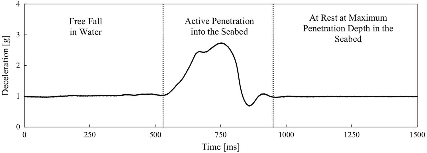
This technical note proposes an algorithm-based methodology for determining the location of the mudline based on portable free-fall penetrometer (PFFP) deployments, that is, where the seabed exhibits a measurable resistance against an object leading to deceleration free-fall in the water column. PFFPs record deceleration at a rate of typically 1–2 kHz, which can be single- and double-integrated to obtain velocity and penetration depth, respectively. The point at which the penetrometer impacts the seabed must be selected to perform this integration and to develop a strength–depth profile (Stark et al. 2022). When carried out manually, the selection of the impact point based on the deceleration-time data is to some degree subjective and can vary from person to person when processing the data (Stark et al. 2022). Fig. 1 illustrates a typical deceleration-time signal of a PFFP deployment centered around the time corresponding to impact and penetration into the seabed. The shown example displays the free-fall through the water columns near terminal velocity. While such a stable free-fall is not always achieved, changes in acceleration beyond the first meter of free-fall are typically small and gradual (typically related to rope drag or a final phase of acceleration), and thus, such changes are not expected to compromise the proposed method. Impacts after shorter distances may require further attention when impact occurs in the initial phase of acceleration. The point of impact is the boundary between free-fall in water and active penetration into the seabed, and should be the point at which a measurable change in deceleration indicates an increase in resistance against the PFFP from the mudline (Fig. 1). Manually selecting the impact point for each impact can be arduous and time consuming when many deployments need to be processed. The method proposed seeks to eliminate the subjectivity in PFFP processing and reduce data processing time as well as the need for an expert data analyst.
Methods
It is hypothesized that the point of impact can be defined as a point where the second-order stationarity of the signal is changing. This is implemented via a search for a change in the standard deviation of the signal using penalized contrasts to reduce the computed residual error, , as detailed in Lavielle (2004), aswhere dec = deceleration-time signal window near the time of active penetration into the seabed; = total number of readings in the deceleration signal; and = point used to divide the deceleration signal into two sections. In the case of the PFFP BlueDrop, each data file contains the data of a full minute. The time window near active penetration into the seabed can typically be considered the time around the maximum deceleration. The point of impact is here defined as the value of which produces the minimum residual error, . This method is preprogrammed in MATLAB using the function findchangepts(dec,“Statistic”,“std”) (Mathworks.com 2022).
(1)
For validation and evaluation, the calculated penetration depth was compared with two different experienced human processors (Researcher 1 and Researcher 2). As a reminder, the calculated penetration depth of the PFFP into the seabed is directly related to the impact selection, as it represents the penetration depth of 0 cm. An impact point later in the deceleration-time signal would result in a smaller calculated penetration depth, and vice versa. Fines content and undrained strength were also compared so that the performance of the proposed automation can be evaluated for different soil types and strengths. Fines content was determined in accordance with ASTM D1140 (ASTM 2017) on samples taken with a ponar grab sampler at the same location as PFFP deployments. In general, higher fines contents result in greater penetration depths of the PFFP (Rahman et al. 2023). Undrained strength was estimated from the PFFP deployments at a depth of 30 cm based on the procedure outlined in Stark et al. (2017) and Stark and Ziotopoulou (2017), using a strain rate factor and a cone tip factor . The most accurate undrained strength profile would require those factors to be calibrated based on soil type. However, such calibration requires availability of quality samples, which is often absent in applications for PFFPs. Thus, the factors proposed in Jaber and Stark (2023) were used for this analysis. The 30-cm depth was arbitrarily chosen so that deployments could directly be compared, regardless of the total penetration depth. In total, 397 deployments were measured in Sequim Bay, Washington, and Mobile Bay, Alabama, covering a range of different soil types and strengths. All deployments utilized a 60° conical tip on the PFFP BlueDrop. The PFFP used offers a hemi-elliptic tip option that simplifies mudline detection in very soft sediments, but it also results in a reduction of penetration depth. Since mudline detection is more challenging for the conical tip, this study is focused on the conical tip only, but it is expected that the proposed method is directly applicable to the hemi-elliptic or any blunter tip geometry as well.
Results and Discussion
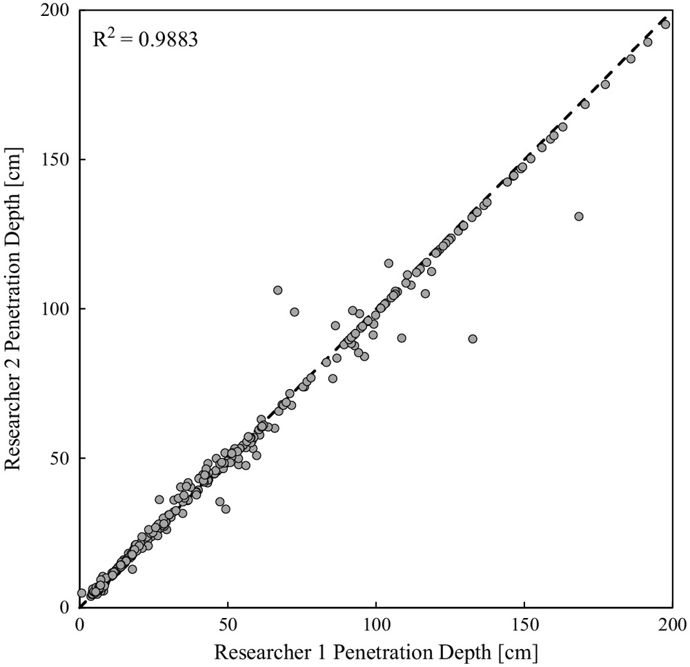
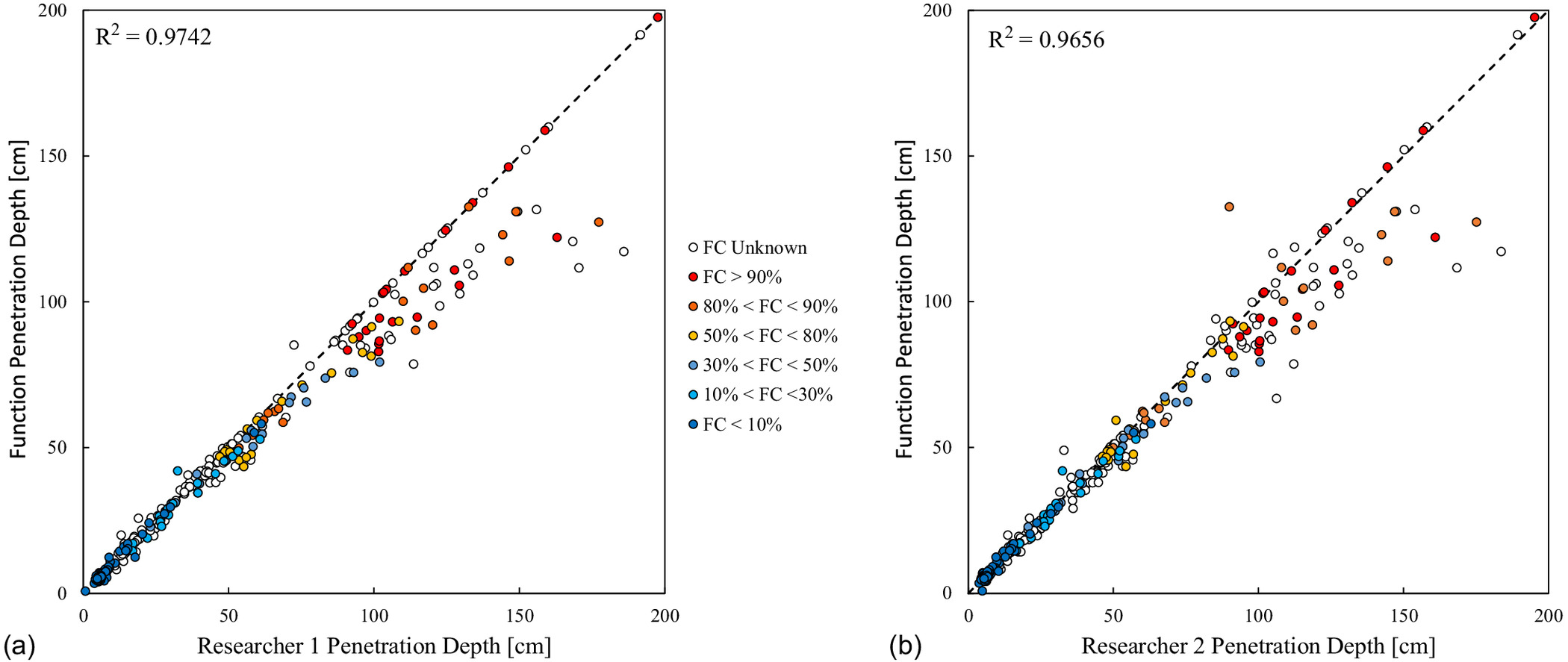
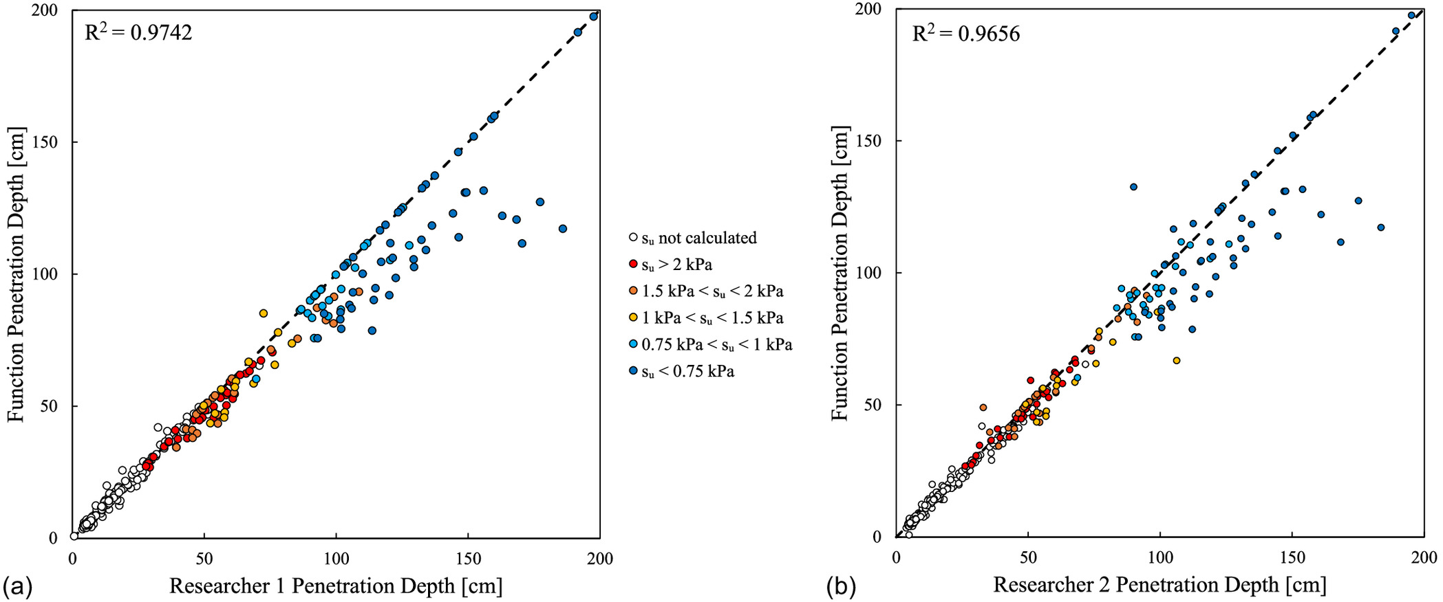
Some subjectivity of the PFFP impact with the seabed is apparent when comparing the penetration depths from two human processors (Fig. 2). Generally, the two human processors selected approximately the same impact point, resulting in similar penetration depths for 85% of the penetration profiles. The difference in the vertical location of the mudline can be determined by multiplying the impact velocity by the time difference between the two selected impact points. In general, the difference of the mudline location between two human processors is less than the resulting difference between the processed penetration depths. Thus, rather than reporting differences in the interpretation of mudline location, we report deviations are reported in terms of penetration depth. For only 15% of the deployments, the penetration depths derived by the two human processors deviated by more than 10% of the total penetration depth. Most deviations between processors occurred for penetration depths of , being representative of soft sediments. When comparing human processors to the proposed automation (Figs. 3 and 4), variability in computed penetration depths is noticeable for penetration depths deeper than about 80 cm (softer soils). Nevertheless, the automation appears to produce reliable results for deployments with penetration depths . An increase in uncertainty can be associated with fines contents exceeding 50% and the undrained shear strength being near or less than 1 kPa. Such low strengths would be difficult to measure by traditional methods, and it may be arguable whether the seabed still exhibits soil-solid behavior or behaves more like a fluid with high suspended sediment concentration. For these cases the automation suggested a later point of impact, that is, a lower penetration depth, representing possibly a more conservative estimate of mudline location by assigning a slightly higher and less ambiguous resistance to the mudline.
Conclusion
Detecting the precise location of the seabed can often be a difficult task, especially in locations where very soft sediment or fluid mud is present. This technical note presents a method to automatically detect the point of impact with the seabed for deployments of a portable free-fall penetrometer (PFFP) by determining the largest change in standard deviation of the signal. The proposed method predicts seabed impact similarly to expert human processors, and the variability in impact selection between the proposed method and a human processor is similar to that of two human processors. However, the observed deviation from two human processors resulted in variability of up to 50 cm of total penetration depth for soils with fines content greater than 50% and an undrained shear strength less than 1.5 kPa. This translates to a difference in vertical mudline location of up to approximately 40 cm, which is less than the deviance in penetration depth. In these cases, the automation identified the mudline generally later and at a greater depth, representing a more conservative but less ambiguous choice; that is, the seabed is associated with a sediment resistance clearly distinguishable from the water column. Using this method can reduce PFFP processing time, eliminate subjectivity in PFFP processing, and possibly eliminate ambiguity in soft seabed surface detection.
Supplemental Materials
File (supplemental_materials_jggefk.gteng-11550_hunstein.zip)
- Download
- 162.93 KB
Data Availability Statement
Some or all data, models, or code that support the findings of this study are available from the corresponding author upon reasonable request.
Acknowledgments
This research is supported by the Strategic Environmental Research and Development Program (SERDP) project MR21-1265 and NRL Grant N00173-19-1-G018. The authors thank Grace Massey for assistance in data collection and Nick Brilli for assistance in data processing. The authors also thank Dana Woodruff and Joseph Haxel from the Pacific Northwest National Laboratory (PNNL) and Joseph Calantoni, Ed Braithwaite III, and Samuel Griffith from the Naval Research Laboratory (NRL).
References
ASTM. 2017. Standard test methods for determining the amount of material finer than 75-μm (no. 200) sieve in soils by washing. ASTM D1140–17. West Conshohocken, PA: ASTM.
Bilici, C., N. Stark, C. T. Friedrichs, and G. M. Massey. 2019. “Coupled sedimentological and geotechnical data analysis of surficial sediment layer characteristics in a tidal estuary.” Geo-Mar. Lett. 39 (3): 175–189. https://doi.org/10.1007/s00367-019-00565-3.
Jaber, R., and N. Stark. 2023. “Geotechnical properties from portable free fall penetrometer in coastal environments.” J. Geotech. Geoenviron. Eng.
Lavielle, M. 2004. “Using penalized contrasts for the change-point problem.” Signal Process. 85 (8): 1501–1510. https://doi.org/10.1016/j.sigpro.2005.01.012.
MathWorks.com. 2022. “Find abrupt changes in a signal–MATLAB findchangepts.” Accessed November 14, 2022. https://www.mathworks.com/help/signal/ref/findchangepts.html#mw_748d5529-e05a-4b55-a3fe-2a12a5772d22.
McAnally, W. H., R. Kirby, S. H. Hodge, T. L. Welp, N. Gresier, P. Shrestha, D. McGowan, and P. Turnipseed. 2016. “Nautical depth for U.S. navigable waterways: A review.” J. Waterway, Port, Coastal, Ocean Eng. 142 (2): 04015014. https://doi.org/10.1061/(ASCE)WW.1943-5460.0000301.
McAnally, W. H., A. Teeter, D. Schoellhamer, C. Friedrichs, D. Hamilton, E. Hayter, P. Shrestha, H. Rodriguez, A. Sheremet, and R. Kirby. 2007. “Management of fluid mud in estuaries, bays, and lakes. II: Measurement, modeling, and management.” J. Hydraul. Eng. 133 (1): 23–38. https://doi.org/10.1061/(ASCE)0733-9429(2007)133:1(23).
Rahman, M. R., E. Hunstein, A. Rodriguez-Marek, N. Stark, G. Massey, K. Dorgan, and C. Cox. 2023. “Probabilistic soil characterization based on portable free fall penetrometer measurements.” In Proc., Coastal Sediments Conf. 2023. Singapore: World Scientific.
Randolph, M., M. Cassidy, and C. Erbich. 2005. “Challenges of offshore geotechnical engineering.” In Proc., 16th Int. Conf. on Soil Mechanics and Geotechnical Engineering, 123–176. London: International Society for Soil Mechanics and Geotechnical Engineering.
Stark, N., N. Parasie, and J. Peuchen. 2022. “Free fall penetrometer deployment strategies and the impact on data analysis: Free fall versus winch-deployed.” In Proc., 4th Int. Symp. in Offshore Geotechnics. Reston, VA: ASCE.
Stark, N., B. Radosavljevic, B. Quinn, and H. Lantuit. 2017. “Application of portable free-fall penetrometer for geotechnical investigation of Arctic nearshore zone.” Can. Geotech. J. 54 (1): 31–46. https://doi.org/10.1139/cgj-2016-0087.
Stark, N., and K. Ziotopoulou. 2017. “Undrained shear strength of offshore sediments from portable free fall penetrometers: Theory, field observations and numerical simulations.” In Proc., of Offshore Site Investigation Geotechnics 8th Int. Conf., 391–399. South Kensington, UK: Society for Underwater Technology.
Sumer, B. M., and J. Fredsøe. 1992. “A review of wave/current-induced scour around pipelines.” Coastal Eng. Proc. 1 (23): 2839–2852. https://doi.org/10.1061/9780872629332.216.
USACE. 2002. CEM: Coastal engineering manual 1110-2-1100. Washington, DC: USACE.
White, D. J., C. Gaudin, N. Boylan, and H. Zhou. 2010. “Interpretation of T-bar penetrometer tests at shallow embedment in very soft soils.” Can. Geotech. J. 47 (2): 218–229. https://doi.org/10.1139/T09-096.
Information & Authors
Information
Published In

Journal of Geotechnical and Geoenvironmental Engineering
Volume 149 • Issue 12 • December 2023
Copyright
This work is made available under the terms of the Creative Commons Attribution 4.0 International license, https://creativecommons.org/licenses/by/4.0/.
History
Received: Dec 12, 2022
Accepted: Jul 19, 2023
Published online: Oct 9, 2023
Published in print: Dec 1, 2023
Discussion open until: Mar 9, 2024
Authors
Metrics & Citations
Metrics
Citations
Download citation
If you have the appropriate software installed, you can download article citation data to the citation manager of your choice. Simply select your manager software from the list below and click Download.