Deployable Tool to Facilitate Cross-Frame Installation in Highly Skewed and Curved Steel Girder Bridges
Publication: Journal of Bridge Engineering
Volume 29, Issue 5
Abstract
This paper introduces a novel, cost-effective deployable tool for the construction of highly skewed and curved steel girder bridges that will provide the necessary geometrical adjustments to the adjacent girders for the fit-up and installation of cross-frames. This tool consists of two cables and one hydraulic jack and would be deployed near the location where a cross-frame needs to be installed. The jack would be extended or contracted to rotate the girders such that they are approximately parallel to one another to achieve the desired geometry for the installation of the cross-frame without requiring force-fitting. After the cross-frame is installed, the deployable tool would be released and reused elsewhere. This paper presents a numerical investigation of the efficacy of this deployable tool in facilitating the installation of cross-frames for two prototype bridges: a highly skewed and a curved steel girder prototype bridge. Three-dimensional (3D) finite-element (FE) analyses of the prototype bridges under steel dead load at the construction increment just before the cross-frames would be installed were performed to first understand the challenges in cross-frame fit-up. The deployable tool was then incorporated into the developed FE model to determine the forces in the system throughout its deployment and the installation of the cross-frames. A control sequence for the deployment was developed and evaluated. For the prototype bridges considered in this research, the peak force in the hydraulic jack was 26.6 kN (5.97 k), meaning that off-the-shelf technologies could be used. The peak von Mises stress in the installed cross-frame was 22.4 MPa (3.25 ksi), indicating that the procedure is not overstressing the system. Overall, this research demonstrates the promise of a new tool to facilitate cross-frame installation in highly skewed and curved steel girder bridges and culminates in recommendations on the use of this technology in the field.
Introduction
The design, fabrication, and installation of cross-frames for curved and highly skewed steel girder bridges can be difficult and time-consuming. In these bridges, the girders twist and deflect such that there is only one fit condition for which the girders are plumb and cross-frames can be installed without force-fitting. The three fit conditions that are typically used in practice are as follows: (1) no-load fit (NLF); (2) steel dead load fit (SDLF); or (3) total dead load fit (TDLF) (Table 1) (NSBA 2016). In a skewed girder bridge, each consecutive girder with identical span length, stiffness, and cross section has a different displacement along a line perpendicular to the structure. If, for example, the cross-frames are detailed for TDLF but are installed under only the displacement of the steel dead load, the erector will be required to apply additional external forces to the girder and cross-frame system to force-fit the connections, causing some temporary torsional and vertical distortion in each of the girders. In a curved girder system, the effects are exaggerated since the girder center of gravity falls outside the line of action between the supports. Steel girders in this system, whether skewed or normal, have both vertical bending and torsion that amplifies the relative displacements between girders and dramatically complicates fit-up (Coletti et al. 2017; NSBA 2016; White et al. 2015; AASHTO/NSBA 2019a; White et al. 2012; Howell and Earls 2007; Domalik et al. 2005). This interaction between interim girder geometry and cross-frame fit can result in the following challenges: (1) unplanned force-fitting and hole reaming may be required in the field; (2) girder webs do not meet plumbness requirements, potentially resulting in higher locked-in stresses, both in the cross-frames and girders; (3) excessive bearing rotations; and (4) poor joint alignment (Coletti et al. 2017; NSBA 2016; White et al. 2015; AASHTO/NSBA 2019a; White et al. 2012). Since the designer or owner chooses one condition for the fabricator/erector, this implies that both girders and cross-frames are designed for the interim conditions and that any locked-in forces in the final composite condition do not compromise the overall load-carrying ability of the system (NSBA 2016).
| Fit condition (corresponding to when girders are plumb) | Description of cross-frame detailing |
|---|---|
| No-load fit | Fit when girders are under no load (i.e., fully supported) |
| Steel dead load fit | Fit when girders are under steel dead load only |
| Total dead load fit | Fit when the girders are under total dead load (including deck) |
Source: Adapted from NSBA (2016).
The more curved and skewed a bridge is, the greater the tendency toward SDLF, given that this enhances constructability in the field. However, even this can present challenges as there are often circumstances where curved girders are picked in pairs with cross-frames already installed (i.e., in the NLF condition) or the use of intermediate props or hold cranes introduces another unforeseen set of assumptions. Any changes impact cross-frame forces, camber, and therefore final girder forces, leaving the potential for new bridges to have overstressed components (Chavel and Earls 2006a, b).
For SDLF or TDLF, the detailer would typically determine the girder geometry by taking the fully cambered no-load girder geometry and subtracting the deflections under the steel dead load or total dead load, respectively. The fully cambered no-load girder geometry would have been determined based on the profile of the road and the total dead load deflections. This calculation would determine the drop as shown in Fig. 1(a) (NSBA 2016). Any transverse slope would also be accounted for in this drop. The cross-frames would typically be detailed to be identical to save fabrication costs and would often be preassembled as rigid, welded units that would be flown in for attachment to the girders. The cross-frames would be attached to one girder first [as shown in Fig. 1(b)] and then attached to the adjacent girder [as shown in Fig. 1(c)]. If SDLF was used and the girders are supported as expected in the aforementioned calculations to determine the drop, then the cross-frames could be installed easily with no force-fitting. However, if TDLF was used or SDLF was used but the girders were supported or loaded differently than how the drop was calculated (e.g., temporarily supported using cranes, partially erected before splices were made), then differential vertical displacements and/or rotations would result and there would be challenges in installing the cross-frames. Fig. 1(d) shows the case of a skewed girder bridge for which the cross-frame was initially bolted onto Girder A and a bolt hole misalignment resulted in Girder B due to a differential vertical displacement. In the case of a curved girder bridge, the girders would also rotate relative to one another, further complicating the cross-frame installation.
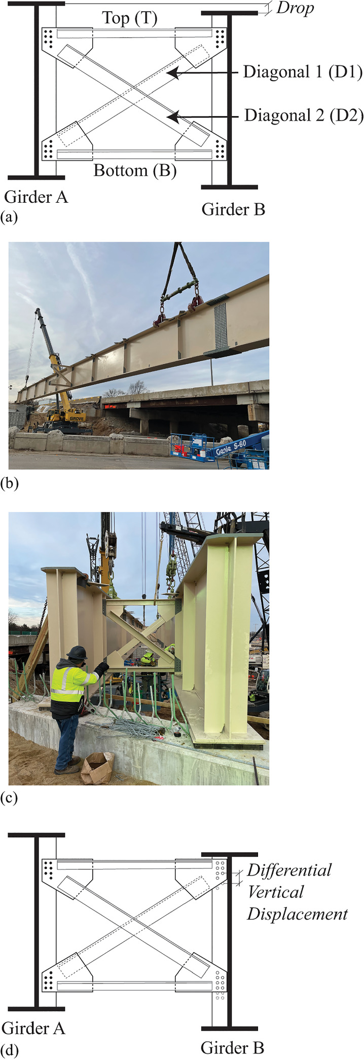
Fig. 1. (a) Drop of adjacent girders; (b) cross-frame installed on a single girder; (c) installation of cross-frame on the adjacent girder; and (d) differential vertical displacement showing misalignment of bolt holes for cross-frame installation.
(Images courtesy of Genesis Structures.)
As discussed previously, even if the cross-frames are detailed for SDLF considering the fully cambered no-load girder geometry and the deflections under the steel dead load, misalignment can still result if the cross-frames are installed at an erection stage for which the girder geometry differs from that which was assumed in design. This is an aspect of the current state of the practice, in which the designer does not presume nor explicitly design for a detailed erection strategy, which might include the following: (1) the use and position of hold cranes and/or temporary supports; (2) the order of girder erection and installation of cross-frames; and (3) which girders to erect in pairs, i.e., cross-frames preinstalled. Perhaps just as importantly, there are inherent shop fabrication tolerances and shop floor limitations associated with the progressive laydown of curved and skewed girder bridges. What is clear is both practices will influence fit-up during erection, and some degree of force-fitting is required. This combination of fit assumptions as part of the design (DLF, SDLF, NDLF), the specific piece-by-piece erection sequence, together with shop fabrication tolerances and progressive assembly limitations, will require a degree of force-fitting. Force-fitting can induce forces/geometry that the designer did not anticipate, potentially invalidating the design. To limit force-fitting during erection, the erection engineer must develop piece-by-piece lifting, handling, and cross-frame connection plans, which adds cost and complexity to the project and may involve re-evaluation of the design by the designer. A significant portion of the fabricator’s cost is to detail and fabricate to a specific fit condition in the shop, with the goal of making field erection easier. Yet, piece-by-piece erection invariably introduces intermediate geometry that must be accommodated by cross-frames, necessitating some amount of force-fitting. In the end, the designer’s prescription of a fit condition and the fabricator’s efforts to achieve this fit geometry can inadvertently make erection more difficult by constraining the erection engineer’s sequence and lifting equipment requirements to a strategy that minimizes cross-frame installation difficulty.
The current practice for misaligned cross-frame installation involves conventional steel erection equipment such as drift pins, come-along tools, chain winches, timber blocking, and crane load manipulation. Such methods are not precise and often involve no definite plan other than installing all required bolts. For example, if the top of the two girder field segments being erected are 2.67 m (8 ft and 9 in.) apart and should be 2.59 m (8 ft and 6 in.) apart, come-along tools might be attached to the opposing top flanges and used to pull the tops together. Likewise, timber blocking might be used between bottom flanges to maintain a particular spacing. To install the bolts in the prefabricated cross-frame, drift pins, additional hand-pulling, and crane load manipulation may all need to be employed. These techniques are performed in an ad hoc manner and may induce unknown stresses in the cross-frames and/or girders, as well as pose safety hazards to the iron workers conducting the tasks.
To address these challenges in fit-up, this paper introduces a novel, cost-effective deployable tool (Fig. 2) that can provide geometrical adjustments in adjacent girders for the installation of cross-frames without force-fitting. Fig. 2(a) shows two girders that are at a target geometry for which cross-frames can be installed without force-fitting. This would be, for example, if the designer and fabricator had detailed the girders for SDLF and the erector had supported the girders in the same way as assumed by the designer and fabricator. This target geometry is defined by the lengths of the diagonals in this configuration, labeled here as L1T and L2T, with the T subscript indicating the lengths are the target lengths. Fig. 2(b) (exaggerated view) shows the challenge of cross-frame installation where differential vertical displacements can occur in highly skewed bridges and both rotations and differential vertical displacements can occur in curved bridges when the geometry at the time the cross-frames would be installed differs from the target geometry (i.e., L1 ≠ L1T and L2 ≠ L2T). This could occur, for example, if the girders were detailed for NLF or TDLF, but the cross-frames are being installed under a different loading condition. It could also occur if the girders were detailed for SDLF, but the cross-frames are installed under different support conditions or loading than anticipated by the designer/fabricator. The deployable tool [Fig. 2(c)]—made up of two cables (which remain nearly constant in length) and a jack—can be installed near the location where a cross-frame should be installed. The jack (e.g., a double-acting hydraulic jack) can then be extended or contracted to rotate the girders to a small angle, α, such that the girders are approximately parallel to one another, and the target geometry is achieved. This rotation changes the dimensions of the diagonals to become L1T and L2T. The cross-frame is then installed without the need for force-fitting and the deployable tool is released. The deployable tool can then be used again at another location. In this study, the geometrical adjustment is considered adequate (i.e., minimal to no force-fitting is required for the installation of a rigid cross-frame) if the diagonal lengths L1 and L2 match their respective target lengths (L1T and L2T) within a threshold of 3.18 mm (1/8 in.) [such that |δL| < 3.18 mm (1/8 in.), where δL = LT − L]. This threshold of 3.18 mm (1/8 in.) is chosen as a reasonable tolerance expectation in steel bridge fabrication and erection, considering that standard size bolt holes are 1.59 mm (1/16 in.) larger than the bolt for 22.2 mm (7/8 in.) diameter bolts or less and 3.18 mm (1/8 in.) larger than the bolt for bolts exceeding 25.4 mm (1 in.) in diameter (AASHTO 2020), indicating that there is play in the bolt holes and a drift pin could be used for alignment.
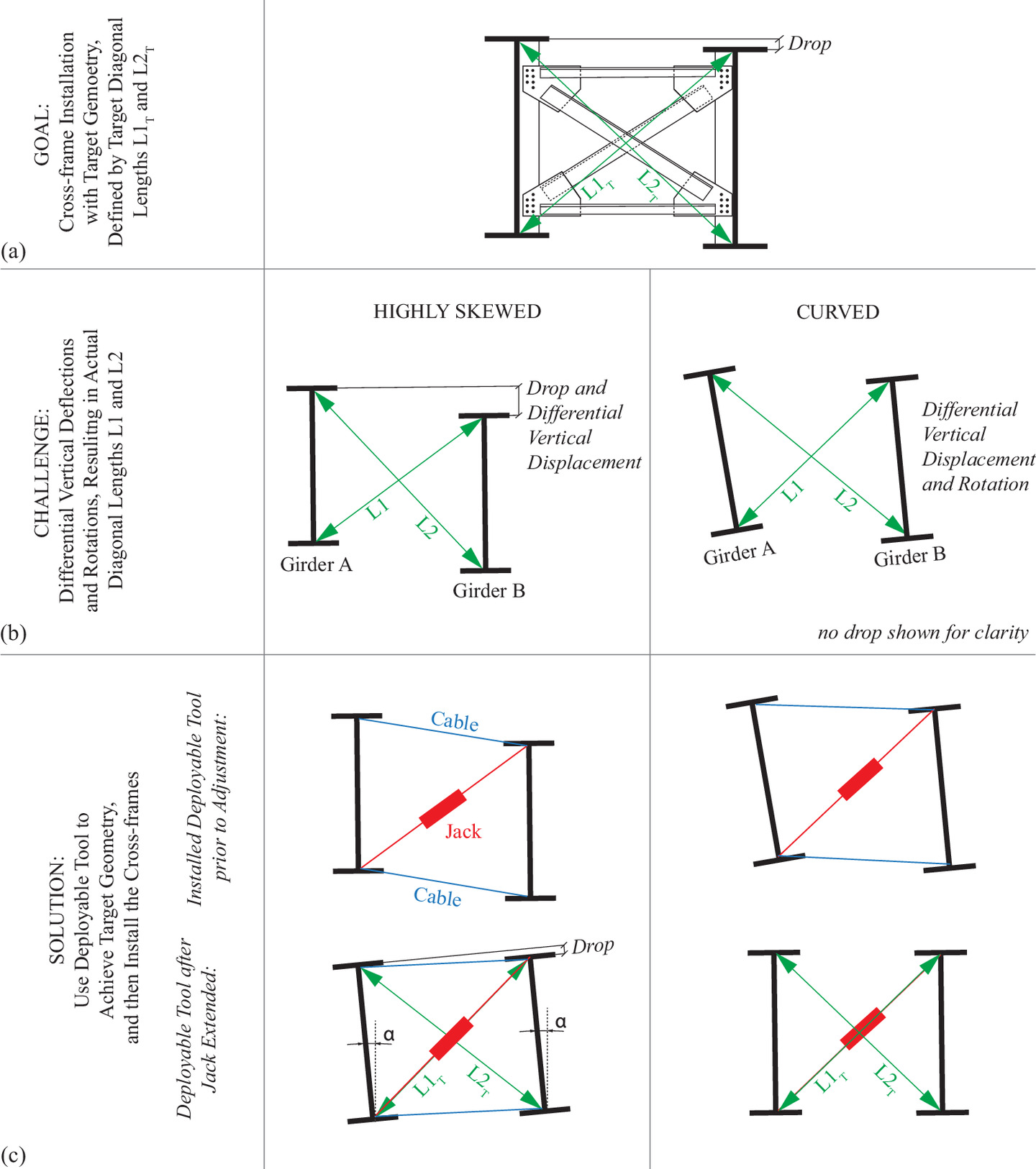
As opposed to the conventional design, fabrication, and construction practices discussed previously, the deployable tool increases flexibility in fabrication and erection while reducing the potential for overstress in the system. It would enable fabrication using one set of fit assumptions and field adjustment to accommodate another set of assumptions, whether that be from different erection assumptions, fabrication tolerances, camber variations, or other unanticipated geometrical variations. The deployable tool has the potential to lead to savings in erection time and cost, as well as increased safety as compared with the current state of the practice. The novelty of the tool is that cross-frames can be installed in a controlled manner and the forces that are imparted into the system are known (as the forces in the jack can be measured). This is a fundamental difference as compared with the state of the practice where force-fitting is performed in an ad hoc manner and the imported forces are unknown and uncontrolled.
Objectives and Scope
The objective of this paper is to demonstrate the efficacy of a novel deployable tool—made up of a double-acting hydraulic jack and two cables—to facilitate the installation of cross-frames in highly skewed and curved steel girder bridges. This tool addresses a major challenge in the design, fabrication, and erection of highly skewed and curved steel girder bridges: that girders twist and deflect such that there is only one fit condition for which the girder is plumb. As a result, the installation of cross-frames in the field can be a difficult task and may require unplanned force-fitting and hole reaming. This paper demonstrates that the deployable tool provides the necessary geometrical adjustments to the adjacent girders to facilitate the installation of cross-frames without force-fitting. Specifically, this paper first numerically investigates the behavior of the highly skewed and curved steel girder bridges under dead loads at a construction increment when cross-frames are installed to understand the challenges in cross-frame fit-up. Then the behavior of the tool during deployment is studied, as well as the behavior of the cross-frames during installation. A low-cost design for the deployable tool is presented, which uses off-the-shelf technologies. Ultimately, this paper demonstrates the promise of a new tool for the safe and cost-effective installation of cross-frames.
Prototype Bridges
To demonstrate the deployable tool in a realistic construction scenario, the behavior of two bridges: a highly skewed and a curved steel girder bridge, that have recently been constructed has been investigated.
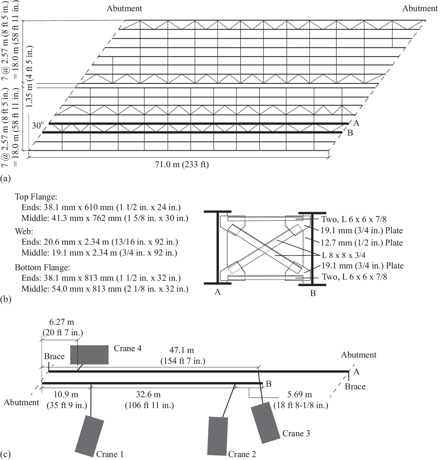
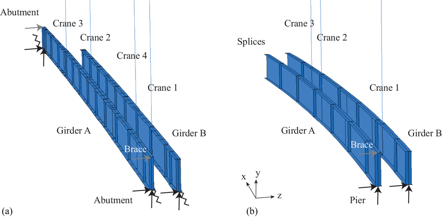
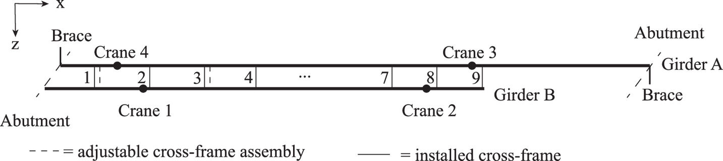
The highly skewed prototype bridge is a simply supported, 71.0-m-long (233-ft) bridge with a skew angle of 30° [Fig. 3(a)]. Fig. 3(b) shows the girder cross sections with the intended cross-frame installed. This research focuses on the behavior of Girders A and B under steel dead load at the construction increment when cross-frames are installed [Fig. 3(c)]. At this construction increment, Girder A has been erected and spans between the two abutments while also being supported by Cranes 3 and 4. Temporary braces are also used to provide lateral stability at the top of the cross section at each abutment for Girder A. Part of Girder B (up to the field splice location) is supported by one abutment and Cranes 1 and 2. Based on the erection engineering documentation, the crane forces at this increment are as follows: Crane 1: 165 kN (37 k), Crane 2: 236 kN (53 k), Crane 3: 369 kN (83 k), and Crane 4: 111 kN (25 k). No cross-frames have been installed at this construction increment. The highly skewed prototype was detailed for TDLF. As the skew angle of this bridge exceeds 20° and the skew index (Is = wg sinθ/Ls, where wg is the bridge width, θ is the skew angle, and Ls is the span length between bearings) is <0.3, guidelines recommend that it be detailed as either TDLF or SDLF (NSBA 2016).
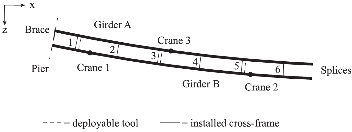
The curved prototype bridge is one span of a curved ramp, with a length of 60.4 m (198 ft) and an inner radius of 295 m (968 ft) [Fig. 4(a)]. Fig. 4(b) shows the girder cross section with the intended cross-frame installed. Note that Fig. 4(b) neglects the cross-slope between the girders and shows a rectangular cross-frame, as opposed to the parallelogram-shaped cross-frame in the actual bridge. This is to reflect the dimensions and shapes used in this paper as the cross-slope between the girders is neglected. The focus of this study is the behavior of Girders A and B under steel dead load at the construction increment when cross-frames are installed [Fig. 4(c)]. Both Girders A and B are supported at one pier and segments extend past the field splice (shown) and onto temporary falsework (not shown). At the pier, the top of the cross section of Girder A is laterally braced with a temporary support. Girder A is also supported by Crane 3 and Girder B is supported by Cranes 1 and 2. Based on the erection engineering documentation, the crane forces at this increment are as follows: Crane 1: 142 kN (32 k), Crane 2: 4.45 kN (1 k), and Crane 3: 142 kN (32 k). No cross-frames have been installed at this construction increment. The curved prototype bridge was detailed for TDLF. As the maximum ratio of the span length, Ls, to the radius, R, is 0.205, current guidelines recommend NLF, with SDLF being acceptable and TDLF to be avoided (NSBA 2016).
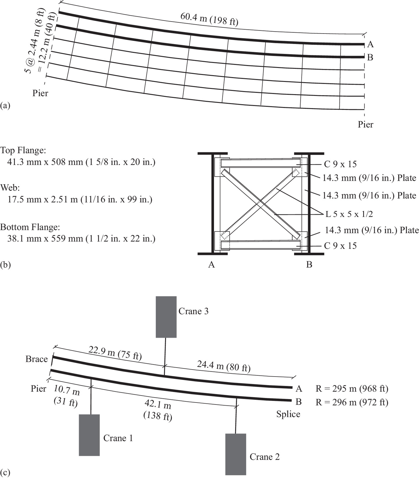
Fig. 5 shows the cross-frame installation for each prototype bridge using conventional methods of erection.
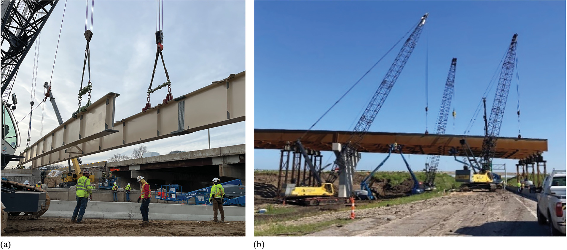
Fig. 5. Photos of the cross-frame installation for the (a) highly skewed prototype bridge; and (b) curved prototype bridge.
(Images courtesy of Genesis Structures.)
Finite-Element Numerical Modeling
Three-dimensional finite-element (FE) analyses of the prototype bridges were performed to (1) understand the differential vertical displacement and/or rotation at the construction increment before cross-frame installation; and (2) investigate the efficacy of the deployable tool.
For both types of analyses, the FE models were built in the software package ABAQUS (2022), using S4R or S3R general-purpose shell elements. Static analyses of the increment of construction when cross-frames would be installed were performed under the steel dead load. Nonlinear geometry was assumed. A linear material model for the steel girders was assumed, with Young’s modulus of 200 GPa (29,000 ksi) and density of 7,850 kg/m3 (0.490 kcf). A mesh refinement study considering only self-weight was conducted on Girder A from the highly skewed prototype, with three mesh sizes: 76.2 mm (3 in.), 152 mm (6 in.), and 304 mm (12 in.). The focus was on investigating the impact of the mesh on the displacements at the bottom of the girder. Table 2 presents the displacements at specific locations and the percent difference compared with the mesh size of 152 mm (6 in.). Based on the results, the displacement values converged and the mesh size of 152 mm (6 in.) was selected.
| Length (m) | Displacement [mm (in.)] | Difference (%) | |||
|---|---|---|---|---|---|
| Mesh A: 76.2 mm (3 in.) | Mesh B: 152 mm (6 in.) | Mesh C: 304 mm (12 in.) | Mesh B−A | Mesh B−C | |
| 10.5 | −12.1 (−0.477) | −12.1 (−0.478) | −12.2 (−0.480) | 0.137 | −0.420 |
| 20.6 | −18.8 (−0.740) | −18.8 (−0.741) | −18.9 (−0.744) | 0.130 | −0.341 |
| 32.2 | −17.3 (−0.680) | −17.3 (−0.680) | −17.3 (−0.683) | 0.0741 | −0.321 |
| 41.7 | −10.8 (−0.424) | −10.8 (−0.424) | −10.8 (−0.426) | 0.0356 | −0.372 |
| 50.1 | −5.69 (−0.224) | −5.69 (−0.224) | −5.71 (−0.225) | −0.0147 | −0.450 |
| 60.4 | −1.68 (−0.0661) | −1.68 (−0.0661) | −1.69 (−0.0666) | −0.0437 | −0.783 |
| 64.2 | −0.134 (−0.00527) | −0.133 (−0.00524) | −0.154 (−0.00606) | −0.692 | −15.7 |
Note: Difference compares displacement of one mesh as compared with another.
Fig. 6 shows the FE models for each of the prototype bridges, including the boundary conditions. Boundary conditions that restrain translation in a direction are indicated by arrows. More specifically, at the abutment for the highly skewed bridge and the pier for the curved bridge, a single node at the intersection of the bottom flange to the web is restrained in the transverse (z-direction) and vertical (y-direction), simulating elastomeric bearings. For the highly skewed bridge, additional longitudinal restraint from the bearings is modeled as springs with a stiffness of 6.13 kN/mm (35 k/in.). This spring stiffness, k, is based on the shear modulus of the reinforced elastomeric bearing, G [1.38 MPa (200 psi)], the area of the bearing pad, A [0.268 m2 (416 in.2)], and the thickness of the elastomer, h [60.3 mm (2.375 in.)], using the following equation:
(1)
Also, for the highly skewed bridge, a single node at the intersection of the top flange to the web is restrained in the transverse direction to simulate temporary erection braces at each end of Girder A. For the curved girder bridge, this restraint representing a temporary erection brace is applied only at the abutment of Girder A. The cranes were modeled as truss elements with Young’s modulus of 103 GPa (15,000 ksi) and cross-sectional area of 1,770 mm2 (2.75 in.2) to represent realistic crane ropes. Displacements were prescribed at the top of the crane truss element to match the displacement of the girders at crane support locations in the model with those in the available construction engineering documents. For the highly skewed bridge, the weight of the splice is included as an additional 8.90 kN (2 k) load on both girder lines. For the curved bridge, Fig. 4(c) shows only a partial view of the construction stage, from the pier to the splices. In fact, the girders extend to temporary falsework. The effect of this additional restraint is modeled numerically through prescribed displacements.
For the highly skewed bridge, the geometry of the web was modeled based on the fully cambered no-load girder geometry, taken from the web blocking diagram of the fabrication drawings for the bridge. The flanges follow the geometry of the web. For the curved bridge, the geometry of the web was assumed to be flat, as there was little difference in camber between the two girder lines in the design, and avoiding doubly curved surfaces reduced the model complexity. For both bridges, no transverse slope was modeled (i.e., both girder lines were assumed to be at the same vertical position), for simplicity. As noted previously, any transverse slope would be accounted for in the calculation for the drop and therefore would not impact the analyses performed in this paper.
No cross-frames were modeled when investigating the behavior under steel dead loads.
When investigating behavior using the deployable tool, a staged FE model was developed to understand behavior at each step of the sequence of installing and using the deployable tool. In the first stage of the FE model, both girders, all cross-frames, and the deployable tool (at each location where it will be used) are in the assembly. Then the boundary conditions are applied and all cross-frames are deactivated (such that the effect of their dead load is not incorporated in the model). In the next stage, the dead load is applied to all active components. This corresponds to Step 1 of the sequence to be discussed subsequently. Then, in individual stages and according to the desired sequence, the deployable tool is utilized or cross-frames are activated.
For the deployable tool, the cables were modeled as tension-only truss elements with Young’s modulus of 103 GPa (15,000 ksi) and cross-sectional area of 269 mm2 (0.417 in.2). The cables are assumed to be wire rope with a diameter of 22.2 mm (0.875 in.), corresponding to this cross-sectional area. Assuming independent wire rope core (IWRC) extra extra improved plow steel (XXIP) with clipped cable termination and a desired safety factor of 4, this diameter of wire rope provides a working tensile load of 44.5 kN (10 k), which conservatively exceeds the tensile load in the cables for either case study shown in the paper (as will be shown subsequently). A double-acting hydraulic jack is modeled as a truss element with Young’s modulus of 200 GPa (29,000 ksi) and cross-sectional area of 2,030 mm2 (3.14 in.2), allowing both tension and compression. Coupling constraints were used to represent pin connections (i.e., translation is coupled in all directions, but rotation is not), joining the cables and the hydraulic jack to the girders.
At a stage when the deployable tool is not in use, the Young’s modulus is reduced to a negligibly small value such that it has an insignificant impact on behavior. At a stage when the deployable tool is in use, the Young’s modulus is changed to the desired 103 GPa (15,000 ksi) value, and a thermal load is applied to the truss element that represents the hydraulic jack, thereby simulating the elongation and/or contraction of the jack. The magnitude of the thermal load (which relates to the magnitude of the increase or decrease in length of the hydraulic jack) was determined based on the difference between the current length of the diagonals, L1 and L2, at the cross-frame location at the current step as compared with the target length of the diagonals, L1T and L2T, at the cross-frame location. When the tool is removed, the Young’s modulus is reduced again to a negligibly small value.
At a stage where a cross-frame would be installed, that part is then activated. The cross-frames are modeled as shell elements with the form and section sizes as shown in Fig. 3(b) for the highly skewed bridge and Fig. 4(b) for the curved bridge. The cross-frames are connected to the girder’s stiffeners using surface-to-surface tie constraints.
Results
Behavior under Steel Dead Load
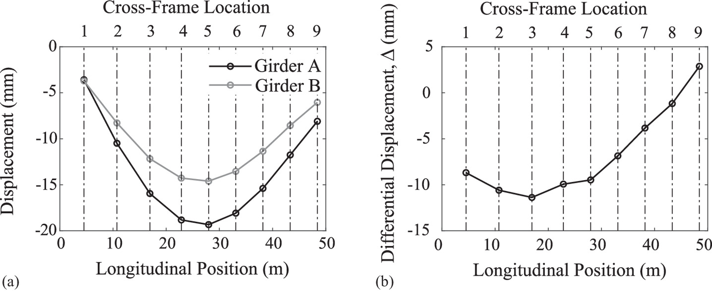
Fig. 7(a) shows the vertical displacement (i.e., y-displacement using the coordinate system of Fig. 6) of Girders A and B under steel dead load at each cross-frame location (vertical dashed line) when no cross-fames have been installed for the skewed girder bridge. To better understand the fit-up problem, Fig. 7(b) shows the differential vertical displacement, Δ, at each cross-frame location calculated as follows:where yDL = vertical coordinate of each girder under steel dead load (with subscripts GA and GB referring to Girder A and Girder B, respectively) at the construction increment when cross-frames would be installed [i.e., the increment shown in Fig. 3(c)]. The drop, d, is calculated by subtracting the deflections under the steel dead load that were calculated in the design documents (which assumed a certain set of boundary conditions) from the fully cambered no-load girder geometry (which corresponds to the web blocking diagram from the fabrication documents). In this paper, it is assumed that SDLF was chosen as the fit condition. The differential vertical displacement, Δ, results because the designer assumed a different set of boundary conditions when calculating the deformed shape of the girders under steel dead load than the actual boundary conditions when the cross-frames are installed at the construction increment shown in Fig. 3(c) (e.g., in this case, the girders are supported by cranes, temporary braces are used, and Girder B is not erected at its full length). In reality, this structure was detailed for TDLF, but the cross-frames are installed under steel dead load. Similar types of differential vertical displacements would result but are not studied in this paper. The peak differential vertical displacement occurs at the location for Cross-frame 3 with a magnitude of 11.4 mm (0.448 in.). In comparison, the differential vertical displacements at the locations of Cross-frames 8 and 9 are <3.18 mm (1/8 in.), such that these two cross-frames could be installed with limited to no force-fitting based on the previously mentioned bolt hole sizes and potential to use a drift pin for alignment. Along the entire girder length, there is negligible rotation, as expected for a straight, skewed bridge.
(2)
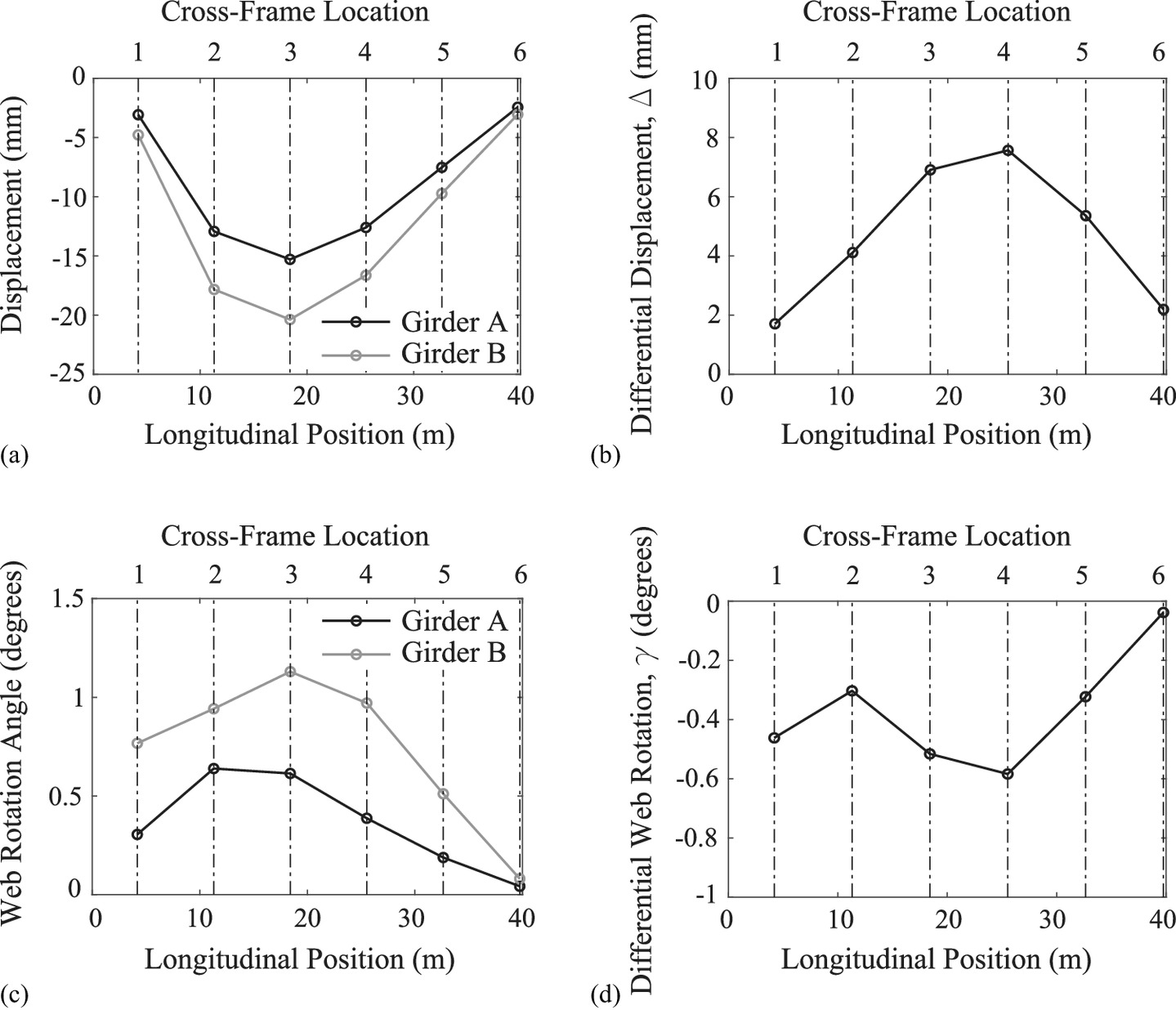
Figs. 8(a and b) show the vertical displacements of each girder and the differential vertical displacement, Δ, between girders under steel dead load only when no cross-frames have been installed for the curved girder bridge. As the drop, d, is assumed to be zero for the case of the curved girder bridge (as camber and transverse cross-slope are ignored), the differential vertical displacement, Δ, between girders is simply the difference in displacements between the two girders. The peak differential vertical displacement is at the Cross-frame 4 location with a magnitude of 7.57 mm (0.298 in.). As expected for a curved girder bridge, each girder rotates under the steel dead load [Fig. 8(c)], with Girder B featuring the peak web rotation at 1.13° at the Cross-frame 3 location. Fig. 8(d) shows the differential web rotations, γ, defined as follows:where βDL = rotation of the web of each girder under steel dead load only, measured relative to the vertical. The peak differential web rotation, γ, occurs at the location of Cross-frame 4 with a magnitude of 0.585°.
(3)
These differential vertical displacements and rotations are unique to the prototype bridges investigated here. Many different variables can impact the differential vertical displacements and rotations, including the overall bridge geometry, girder cross-sectional properties, and erection plan, among others.
Behavior Using Deployable Tool
Given the differential vertical displacements and/or girder rotations found for the prototype bridges, a control sequence of when and where the deployable tool should be used, including the installation of the cross-frames, was developed.
The overall philosophy for determining the sequence is based on the aim of (1) simplifying the necessary analyses to be performed by the engineer to use the deployable tool; and (2) minimizing the number of times the deployable tool would need to be used to install the cross-frames as rapidly as possible. More specifically related to the former, it is assumed that the engineer responsible for the erection plan first performs an analysis of the construction stage when cross-frames would be installed to determine the differential vertical displacements and rotations under steel dead load (with no cross-frames included in the analysis). If based on this analysis, the magnitude of the differential vertical displacement, Δ, is <3.18 mm (1/8 in.) and the differential rotation, γ, is <0.596° at a cross-frame location, then a cross-frame could be installed with limited or no force-fitting and the deployable tool is not needed. The 3.18 mm (1/8 in.) limit for the differential vertical displacement, Δ, relates to the aforementioned threshold that would enable bolt-hole alignment via drift pin. The 0.596° limit on the differential rotation, γ, relates to the accepted tolerance for web plumbness of 3.18 mm (1/8 in.) of layover per 305 mm (1 ft) of web depth (AASHTO/NSBA 2019b). For all other cross-frame locations, the deployable tool could be used to facilitate cross-frame installation. This section will describe the determined sequence for both of the prototype bridges, including evaluating the forces in the deployable tool during adjustment and the stresses in the installed cross-frames. More general recommendations for using the deployable tool are provided in the next section.
Table 3 shows the control sequence for deploying the tool and installing the cross-frames for the highly skewed bridge, with the locations indicated in Fig. 9. Each step indicates a phase in the erection sequence. These also correspond to independent stages in the FE model, as described previously. Only one deployable tool is used in the sequence, but it is moved to different locations at different points in the sequence. Recalling the differential vertical displacements in Fig. 7(b), Cross-frames 8 and 9 could be installed with no or minimal force-fitting, as the differential vertical displacement, Δ, is <3.18 mm (1/8 in.) and the differential rotations, γ, are negligible. These are therefore selected to be installed first (i.e., in Step 2) without the need for the deployable tool. Then the deployable tool would be deployed near the cross-frame location with the largest magnitude of δL. However, if the differential vertical displacements, Δ, and/or differential rotations, γ, near a boundary condition exceed the aforementioned thresholds, the deployable tool should be used for the cross-frame nearest the boundary condition, as the boundary conditions can make the geometrical adjustments of the girders more challenging. As the differential vertical displacements, Δ, at the Cross-frame 1 location exceed the threshold and Cross-frame 1 is near the boundary condition, the deployable tool is used to install Cross-frame 1 first. In Step 3, the deployable tool is installed 152 mm (6 in.) away from the Cross-frame 1 location. The jack is extended (using the thermal load discussed previously) until |δL| < 3.18 mm (1/8 in.) for both diagonals L1 and L2, with forces in the deployable tool as given in Table 3. Cross-frame 1 is installed in Step 4 and the deployable tool is removed in Step 5. This release results in stresses being imparted into Cross-frame 1 (Fig. 10, Table 4).
| Step | Task | Location | Forces in deployable tool components [kN (k)] | ||
|---|---|---|---|---|---|
| Jack | Top cable | Bottom cable | |||
| 1 | Initial | — | — | — | — |
| 2 | Install cross-frame | 8,9 | — | — | — |
| 3 | Install deployable tool | 1 | −16.8 (−3.79) | 0.343 (0.0771) | 7.79 (1.75) |
| 4 | Install cross-frame | 1 | −16.8 (−3.78) | 0.276 (0.0620) | 7.90 (1.78) |
| 5 | Remove deployable tool | 1 | — | — | — |
| 6 | Install cross-frame | 7 | — | — | — |
| 7 | Install deployable tool | 3 | 1.02 (0.229) | 2.86 (0.643) | 0.267 (0.298) |
| 8 | Install cross-frame | 3 | 1.17 (0.262) | 2.81 (0.633) | 0.354 (0.0795) |
| 9 | Remove deployable tool | 3 | — | — | — |
| 10 | Install cross-frame | 2,4 | — | — | — |
| Step | Cross-frame 1 stresses [MPa (ksi)] | Cross-frame 7 stresses [MPa (ksi)] | ||||||
|---|---|---|---|---|---|---|---|---|
| D1 | D2 | T | B | D1 | D2 | T | B | |
| 4 | 5.78 (0.838) | 4.64 (0.672) | 3.38 (0.490) | 3.03 (0.439) | — | — | — | — |
| 5 | 8.85 (1.28) | 9.03 (1.31) | 8.12 (1.18) | 4.41 (0.639) | — | — | — | — |
| 6 | 9.07 (1.32) | 8.84 (1.28) | 8.13 (1.18) | 4.62 (0.670) | 5.98 (0.867) | 5.36 (0.778) | 3.10 (0.450) | 4.03 (0.585) |
| 7 | 8.44 (1.22) | 9.7 (1.40) | 18.9 (2.74) | 8.39 (1.22) | 5.99 (0.869) | 5.18 (0.751) | 2.94 (0.426) | 7.67 (1.11) |
| 8 | 8.49 (1.23) | 9.4 (1.37) | 19.0 (2.76) | 8.51 (1.23) | 5.87 (0.851) | 5.22 (0.757) | 3.05 (0.442) | 8.01 (1.16) |
| 9 | 8.50 (1.23) | 9.4 (1.37) | 19.1 (2.77) | 8.52 (1.24) | 5.85 (0.848) | 5.23 (0.758) | 3.05 (0.442) | 7.97 (1.16) |
| 10 | 8.50 (1.23) | 8.8 (1.28) | 19.1 (2.77) | 8.83 (1.28) | 5.56 (0.806) | 5.31 (0.770) | 3.39 (0.492) | 8.89 (1.29) |
Note: D1 = Diagonal 1; D2 = Diagonal 2; T = top; and B = bottom of cross-frame [Fig. 1(a)].
After installing Cross-frame 1, it was observed numerically (and could be observed physically by the contractor), that location Cross-frame 7 now meets the |δL| < 3.18 mm (1/8 in.) for both diagonals L1 and L2. Cross-frame 7 is then installed in Step 6. Note that Cross-frame 7 met this criterion in Step 1 and could have been installed in Step 2. However, this was not done in this paper because the initial decisions on which cross-frame to install at Step 2 were made based solely on the differential vertical displacements, Δ. Then, the deployable tool is used to install the cross-frame that has the largest magnitude of δL, i.e., Cross-frame 3. The deployable tool would again be installed 152 mm (6 in.) away longitudinally from the location of Cross-frame 3. In this case, the deployable tool is extended based on the current lengths L1 and L2 as compared with the target lengths L1T and L2T. Then, Cross-frame 3 would be installed, using a similar procedure. It was then observed that the locations for Cross-frames 2 and 4 now meet the |δL| < 3.18 mm (1/8 in.) threshold for both diagonals L1 and L2. Cross-frames 2 and 4 were then installed. And the procedure could continue until all cross-frames were installed.
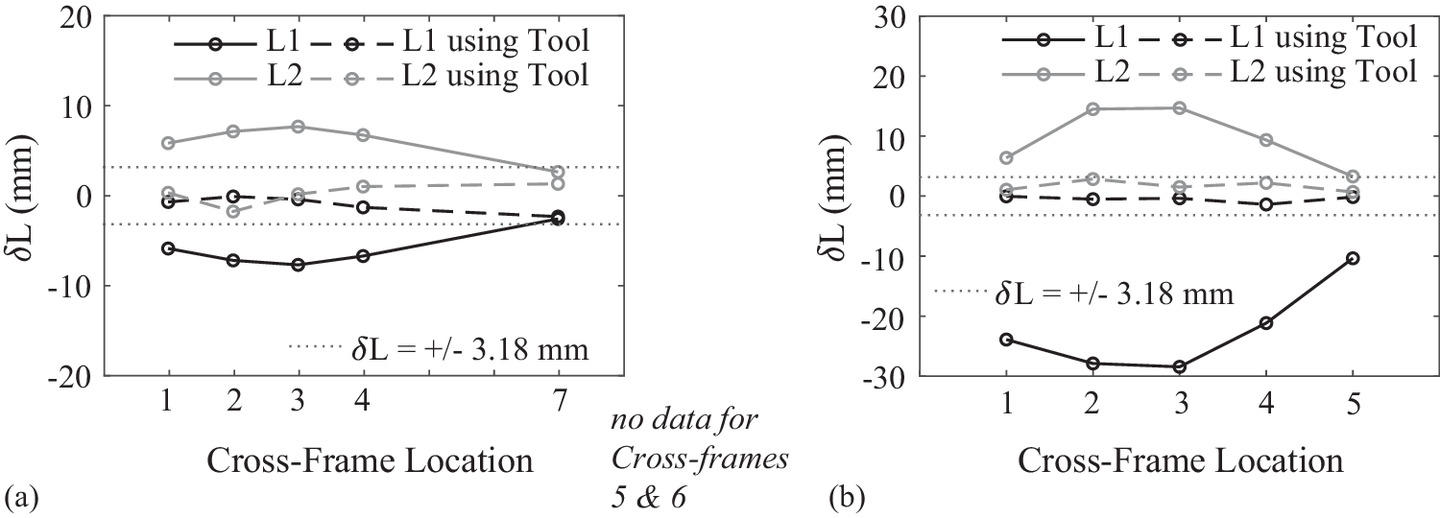
Importantly, throughout the sequence, the force in the jack never exceeded 16.8 kN (3.79 k), which could be readily achieved with off-the-shelf technologies, as will be discussed subsequently (Table 3). Further, the stresses in the permanent cross-frames remain low [peak von Mises stress is 19.1 MPa (2.77 ksi); Tables 4 and 5], indicating that the procedure is not overstressing components. Additionally, the crane forces remained almost constant throughout the implementation of the deployable tool, indicating that the process was not inducing undesirable additional forces on the cranes. Comparing when only the dead load of the steel girders was acting with all other stages of the study, the peak change in force in a crane was 6.87% [i.e., 237 kN (53.4 k) in Crane 2 in Step 1 compared with 254 kN (57.1 k) in Step 10]. Fig. 11(a) provides a fit-up comparison if the deployable tool is not used (solid) compared with if it is used (dashed). The vertical axis indicates the difference, δL for lengths L1 and L2. The threshold of |δL| < 3.18 mm (1/8 in.) (dotted lines) taken as an acceptable length difference for which force-fitting would not be required was readily achieved using the deployable tool.
| Step | Cross-frame 3 stresses [MPa (ksi)] | Cross-frame 2 stresses [MPa (ksi)] | Cross-frame 4 stresses [MPa (ksi)] | |||||||||
|---|---|---|---|---|---|---|---|---|---|---|---|---|
| D1 | D2 | T | B | D1 | D2 | T | B | D1 | D2 | T | B | |
| 8 | 5.61 (0.814) | 6.84 (0.992) | 3.37 (0.489) | 3.42 (0.496) | — | — | — | — | — | — | — | — |
| 9 | 6.27 (0.909) | 7.08 (1.027) | 3.53 (0.513) | 3.90 (0.565) | — | — | — | — | — | — | — | — |
| 10 | 6.06 (0.880) | 7.28 (1.056) | 3.91 (0.568) | 3.95 (0.573) | 6.29 (0.912) | 5.57 (0.808) | 15.3 (2.22) | 4.01 (0.582) | 5.46 (0.793) | 7.17 (1.04) | 3.44 (0.498) | 2.46 (0.357) |
Note: D1 = Diagonal 1; D2 = Diagonal 2; T = top; and B = bottom of cross-frame [Fig. 1(a)].
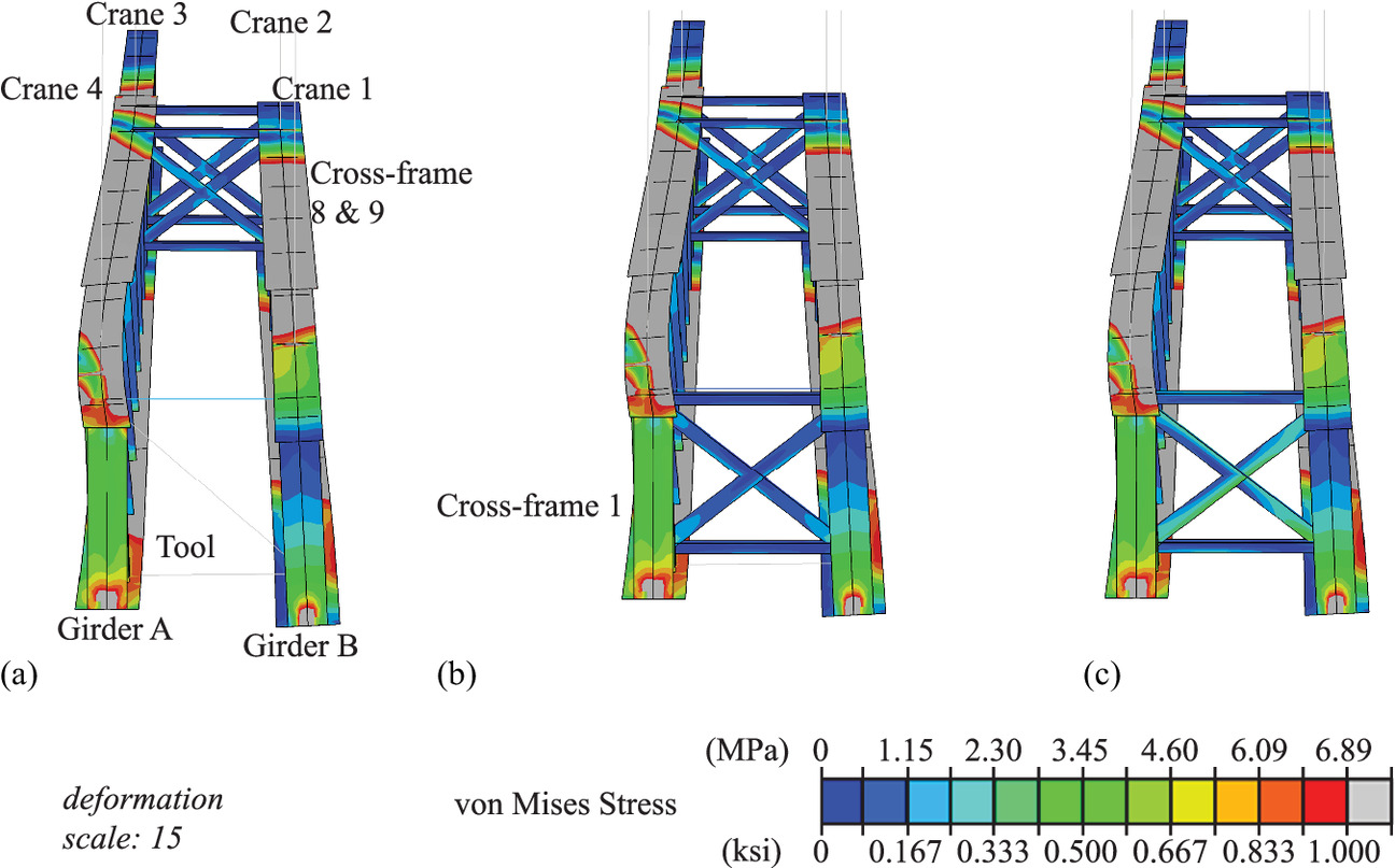
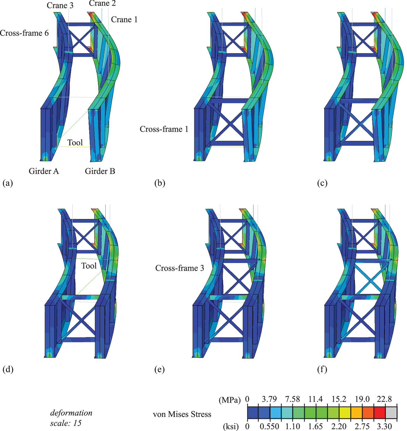
A similar approach was evaluated for the curved prototype bridge, with Table 6 indicating the control sequence with locations identified in Fig. 12. First, Cross-frame 6 is installed, as it meets the thresholds for the differential vertical displacements, Δ, and differential rotations, γ [Figs. 8(b and d)]. Then Cross-frame 1 was selected for installation, as it is nearest to a boundary condition and the differential vertical displacements, Δ, and differential rotations, γ, do not meet the thresholds. The deployable tool is installed 152 mm (6 in.) away from where Cross-frame 1 would be and the jack is extended until |δL| < 3.18 mm (1/8 in.) for both diagonals. Table 6 shows the forces in the deployable tool during this process, Table 7 shows the stresses developed in Cross-frame 1, and Figs. 13(a–c) show the stress contours during this process. The deployable tool is then used to install Cross-frame 3, as it has the largest magnitude of δL among the remaining cross-frames to be installed [Tables 6, 7 and Figs. 13(d and e)]. With Cross-frame 3 installed, the Cross-frame 2 location now meets the |δL| < 3.18 mm (1/8 in.) for both diagonals and it can be installed without needing the deployable tool (Table 8). The deployable tool is then used again for Cross-frame 5 (Table 8). The deployable tool was not needed to install Cross-frame 4, as the installation of Cross-frame 5 had provided sufficient geometrical adjustments such that |δL| < 3.18 mm (1/8 in.) for both diagonals for Cross-frame 4.
| Step | Task | Location | Forces in deployable tool components [kN (k)] | ||
|---|---|---|---|---|---|
| Jack | Top cable | Bottom cable | |||
| 1 | Initial | — | — | — | — |
| 2 | Install cross-frame | 6 | — | — | — |
| 3 | Install deployable tool | 1 | 17.7 (3.97) | −8.96 (−2.01) | −4.58 (−1.03) |
| 4 | Install cross-frame | 1 | 17.8 (4.00) | −8.98 (−2.02) | −4.56 (−1.02) |
| 5 | Remove deployable tool | 1 | — | — | — |
| 6 | Install deployable tool | 3 | 26.47 (5.95) | −2.83 (−0.635) | −14.89 (−3.35) |
| 7 | Install cross-frame | 3 | 26.56 (5.97) | −2.85 (−0.640) | −14.87 (−3.34) |
| 8 | Remove deployable tool | 3 | — | — | — |
| 9 | Install cross-frame | 2 | — | — | — |
| 10 | Install deployable tool | 5 | 16.8 (3.77) | −1.24 (−0.278) | −8.97 (−2.02) |
| 11 | Install cross-frame | 5 | 17.9 (3.77) | −1.21 (−0.273) | −8.95 (−2.01) |
| 12 | Remove deployable tool | 5 | — | — | — |
| 13 | Install cross-frame | 4 | — | — | — |
| Step | Cross-frame 1 stresses [MPa (ksi)] | Cross-frame 3 stresses [MPa (ksi)] | ||||||
|---|---|---|---|---|---|---|---|---|
| D1 | D2 | T | B | D1 | D2 | T | B | |
| 4 | 2.52 (0.365) | 2.77 (0.402) | 1.31 (0.189) | 1.15 (0.167) | — | — | — | — |
| 5 | 5.41 (0.785) | 5.16 (0.748) | 5.92 (0.859) | 2.67 (0.388) | — | — | — | — |
| 6 | 27.9 (4.05) | 5.47 (0.793) | 19.6 (2.84) | 7.03 (1.02) | — | — | — | — |
| 7 | 27.9 (4.04) | 5.44 (0.789) | 19.5 (2.82) | 7.01 (1.03) | 2.63 (0.381) | 2.83 (0.410) | 1.21 (0.175) | 1.33 (0.192) |
| 8 | 28.1 (4.07) | 5.59 (0.811) | 19.6 (2.85) | 7.10 (1.03) | 7.14 (1.04) | 8.22 (1.19) | 8.34 (1.21) | 5.03 (0.729) |
| 9 | 28.0 (4.07) | 5.59 (0.810) | 19.6 (2.84) | 7.09 (1.03) | 7.18 (1.04) | 8.26 (1.20) | 8.37 (1.21) | 5.06 (0.733) |
| 10 | 29.2 (4.23) | 5.08 (0.737) | 20.5 (2.97) | 6.39 (0.927) | 8.92 (1.29) | 7.25 (1.05) | 9.20 (1.33) | 5.21 (0.756) |
| 11 | 29.2 (4.23) | 5.08 (0.737) | 20.4 (2.96) | 6.38 (0.925) | 8.92 (1.29) | 7.27 (1.05) | 9.20 (1.33) | 5.21 (0.756) |
| 12 | 29.2 (4.23) | 5.08 (0.736) | 20.4 (2.97) | 6.37 (0.924) | 8.94 (1.30) | 7.27 (1.05) | 9.20 (1.33) | 5.21 (0.756) |
| 13 | 29.2 (4.23) | 5.07 (0.735) | 20.5 (2.96) | 6.35 (0.921) | 8.97 (1.30) | 7.29 (1.06) | 9.21 (1.34) | 5.22 (0.757) |
Note: D1 = Diagonal 1; D2 = Diagonal 2; T = top; and B = bottom of cross-frame [Fig. 1(a)].
| Step | Cross-frame 2 stresses [MPa (ksi)] | Cross-frame 5 stresses [MPa (ksi)] | Cross-frame 4 stresses [MPa (ksi)] | |||||||||
|---|---|---|---|---|---|---|---|---|---|---|---|---|
| D1 | D2 | T | B | D1 | D2 | T | B | D1 | D2 | T | B | |
| 9 | 2.65 (0.384) | 2.81 (0.408) | 1.22 (0.177) | 1.11 (0.161) | — | — | — | — | — | — | — | — |
| 10 | 2.55 (0.369) | 4.00 (0.580) | 2.63 (0.382) | 2.07 (0.301) | — | — | — | — | — | — | — | — |
| 11 | 2.55 (0.369) | 4.00 (0.580) | 2.62 (0.380) | 2.08 (0.302) | 2.76 (0.401) | 2.79 (0.405) | 1.25 (0.181) | 1.18 (0.172) | — | — | — | — |
| 12 | 2.55 (0.369) | 4.01 (0.581) | 2.63 (0.381) | 2.09 (0.303) | 5.26 (0.763) | 4.87 (0.707) | 6.49 (0.941) | 3.99 (0.578) | — | — | — | — |
| 13 | 2.54 (0.369) | 4.02 (0.583) | 2.62 (0.380) | 2.10 (0.305) | 5.27 (0.764) | 4.88 (0.708) | 6.52 (0.946) | 4.01 (0.581) | 2.71 (0.394) | 2.82 (0.409) | 1.32 (0.191) | 1.10 (0.160) |
Note: D1 = Diagonal 1; D2 = Diagonal 2; T = top; and B = bottom of cross-frame [Fig. 1(a)].
Throughout the sequence, the peak force in the jack is 26.6 kN (5.97 k), which is higher than that for the highly skewed bridge [i.e., 16.0 kN (3.60 k)]. As shown in Tables 7 and 8, the peak stresses in the installed cross-frames are overall very low [with a peak stress of 10.8 MPa (1.57 ksi)], again demonstrating that the deployable tool does not overstress the cross-frames. As in the case of the highly skewed bridge, the crane forces were reduced during the implementation of the deployable tool: the peak difference in crane force (as compared with when only dead load is acting) is 12.5% [i.e., 161 kN (36.3 k) in Crane 1 in Step 1 compared with 141 kN (31.8 k) in Step 14], indicating that additional forces are not being put into the cranes. Fig. 11(b) shows the curved prototype bridge fit-up comparison if the deployable tool is not used (solid) compared with if it is used (dashed). This demonstrates that the deployable tool provides acceptable fit-up conditions for the cross-frames that would eliminate force-fitting.
Recommendations
Based on these case studies, recommendations for the use of the deployable tool, including selecting a deployment sequence, are as follows:
1.
The engineer responsible for the erection plan should first determine the differential vertical displacements, Δ, and differential rotations, γ, of adjacent girders under steel dead load at the construction increment in which cross-frame installation is planned to take place.
2.
If the differential vertical displacement, Δ, is <3.18 mm (1/8 in.) and the different rotation, γ, is <0.596° at the location where a cross-frame is to be installed, then that cross-frame can be installed with no or minimal force-fitting and it should be installed first.
3.
The deployable tool should be used to facilitate the installation of the other cross-frames. It is recommended that the cross-frame location with the highest magnitude of δL, in either diagonal direction, be installed next. This could be calculated numerically or observed physically by the contractor.
4.
If, however, the cross-frame nearest the support has a differential vertical displacement, Δ, >3.18 mm (1/8 in.) and/or the different rotation, γ, >0.596°, then that cross-frame should be installed first, as girder geometrical adjustment can be challenging owing to the restraint provided by the support.
5.
When a threshold of |δL| < 3.18 mm (1/8 in.) for both diagonals is met, a cross-frame can be installed with limited or no force-fitting.
6.
Each time the deployable tool is used to install a specific cross-frame, the contractor should check to see if any other cross-frames can also be installed at that step in the sequence. This can occur while the tool is in use or after the tool has been removed.
7.
The engineer can also provide flexibility to the contractor to use the deployable tool as needed, by, for example, prescribing a maximum force that can be used in the jack to achieve the necessary geometrical adjustments. This allows for the contractor to overcome unanticipated geometry issues that can arise during erection.
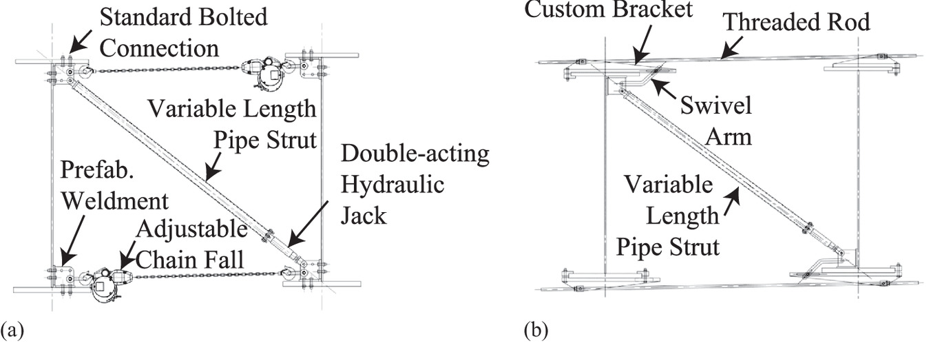
Considering realistic hardware for the deployable tool, Fig. 14 shows two more detailed schematics. In this concept, the tension members, previously referred to as cables, would be adjustable, off-the-shelf items such as chain falls or high-strength threaded rods. These members would remain constant in length during the deployment but are adjustable to adapt to different girder spacings, whether that be on the same bridge or when used on a different bridge. Similarly, the compression member that was previously simply referred to as a jack would be made up of a variable length pipe strut and an off-the-shelf double-acting hydraulic cylinder. Again, the variable length pipe strut would provide adaptability for different girder spacings and/or girder depths. A double-acting hydraulic cylinder with 98.8-kN (11.1-t) capacity and 254-mm (10-in.) stroke would provide sufficient capabilities for the two case studies investigated in this paper. The option shown in Fig. 14(a) shows these components bolted onto the girders. The alternative option in Fig. 14(b) uses customized brackets that would enable clamping to girders as opposed to requiring that holes be drilled. Either of these designs would provide the necessary capacities for the deployable tool, while also being adaptable to varying girder spacings and girder depths. An engineer would, of course, need to verify that the hydraulic cylinder and cables of the deployable tool have sufficient capacity for their implementation prior to use.
Conclusions
This research numerically demonstrated the efficacy of a new deployable tool to aid in the installation of cross-frames of two prototype bridges: a highly skewed and a curved steel girder prototype bridge. The key findings from this research are as follows:
1.
The deployable tool can provide the necessary geometrical adjustments to overcome the differential vertical displacements [on the order of 12.7 mm (0.5 in.)] and differential rotations (on the order of 0.5°) observed in the highly skewed and curved girder prototype bridges.
2.
During deployment, the hydraulic jack would need to exert a peak force of 26.6 kN (5.97 k) for the prototype bridges investigated. Thus, an off-the-shelf double-acting hydraulic cylinder with 98.8-kN (11.1-t) capacity and 254-mm (10-in.) stroke would provide sufficient capabilities for realistic scenarios.
3.
When the cross-frames are installed, and the deployable tool is released, the peak von Mises stress in any component of the cross-frame for either prototype bridge was 29.2 MPa (4.23 ksi). This indicates that the deployable tool does not overstress the cross-frame components.
4.
Recommendations for the use of the deployable tool were developed.
5.
Two designs for the deployable tools were proposed. One uses an approach where a jack and two chain falls can be bolted to girders and the other uses a more customized bracket system to connect the deployable tool to the girders. Either approach could be readily fabricated and used in the field and is adaptable to varying girder spacings and/or girder depths.
This research focused on numerically evaluating the behavior of two adjacent girder lines when using the deployable tool. Prototype demonstration and experimental testing will be important next steps in evaluating this technology. In this future investigation, it will be important to understand and quantify the time to deploy, secure, operate, and release the tool. Future research will also consider the fit-up of additional girder lines, as well as the behavior after the deck is poured (i.e., under total dead load). Girder spacing and girder depth limits should be defined according to the deployable tool developed, given the maximum and minimum lengths that the jack could achieve. In addition, the maximum capacity of the deployable tool should be evaluated. These are limiting factors that should be investigated in future research during the prototype demonstration.
Further, this paper has numerically investigated the behavior of the girders and the deployable tool in an ideal environment, when only dead load is considered. In reality, there are many other real-world factors that are at play during cross-frame installation, including temperature variations, wind loads, and vibrations. Such factors would need to be taken into account by the engineer. Regardless of these additional factors, the deployable tool provides flexibility for on-site adjustments to variable conditions. The hydraulic jack could be extended or retracted to be able to achieve geometric variations that may differ from what was initially anticipated. With the hydraulic jack, the engineer will now know how much force is being imparted into the system and can make sound judgements on what is acceptable (e.g., an engineer could prescribe beforehand a range of acceptable forces).
While the focus of this paper has been on the use of the deployable tool to facilitate cross-frame fit-up for highly skewed and curved girder bridges, the tool also has the potential to aid in the addition of girder lines to widen a bridge. A potential additional application includes stabilizing girders during deck replacement.
Data Availability Statement
All data, models, or codes that support the findings of this study are available from the corresponding author upon reasonable request.
Acknowledgments
This research was supported by the Innovation Deserving Exploratory Analysis (IDEA) Program of the Transportation Research Board of the National Academies of Sciences, Engineering, and Medicine. The authors would like to acknowledge the contributions of the current Project Advisors Farhad Ansari, Patricia Leavenworth, and Jason Provines, as well as former Project Advisor Ahmad Abu-Hawash. The authors are also grateful for the feedback from the Expert Panel, including Stephanie Wagner, Mark Hurt, Ronnie Medlock, and Bill Lally. The authors also appreciate the support of IDEA Program Manager Inam Jawed.
References
AASHTO. 2020. Load and resistance factor design (LRFD) bridge design specifications, customary U.S. units. 9th ed. Washington, DC: AASHTO.
AASHTO/NSBA (National Steel Bridge Alliance). 2019a. Guidelines for steel girder bridge analysis. G13.-2019. Washington, DC: AASHTO and NSBA.
AASHTO/NSBA (National Steel Bridge Alliance). 2019b. Steel bridge erection guide specification. S10.1-2019. Washington, DC: AASHTO and NSBA.
ABAQUS. 2022. ABAQUS/standard analysis user’s manual. Waltham, MA: Dassault Systemes.
Chavel, B. W., and C. J. Earls. 2006a. “Construction of a horizontally curved steel I-girder bridge. Part I: Erection sequence.” J. Bridge Eng. 11 (1): 81–90. https://doi.org/10.1061/(ASCE)1084-0702(2006)11:1(81).
Chavel, B. W., and C. J. Earls. 2006b. “Construction of a horizontally curved steel I-girder bridge. Part II: Inconsistent detailing.” J. Bridge Eng. 11 (1): 91–98. https://doi.org/10.1061/(ASCE)1084-0702(2006)11:1(91).
Coletti, D. A., D. W. White, T. V. Nguyen, B. W. Chavel, M. A. Grubb, and C. G. Boring. 2017. “Reliable fit-up of steel I-girder bridges.” Transp. Res. Rec. J. Transp. Res. Board 2642 (1): 1–8. https://doi.org/10.3141/2642-01.
Domalik, D. E., J. F. Shura, and D. G. Linzell. 2005. “The design and field monitoring of a horizontally curved steel plate girder bridge.” In Transp. Res. Rec. J. Transp. Res. Board. 1928 (1): 83–91. https://doi.org/10.1177/0361198105192800109.
Howell, T. D., and C. J. Earls. 2007. “Curved steel I-girder bridge response during construction loading: Effects of web plumbness.” J. Bridge Eng. 12 (4): 485–493. https://doi.org/10.1061/(ASCE)1084-0702(2007)12:4(485).
NSBA (National Steel Bridge Alliance). 2016. Skewed and curved steel I-girder bridge fit. Chicago: NSBA.
White, D. W., et al. 2012. Guidelines for analysis methods and construction engineering of curved and skewed steel girder bridges. NCHRP Rep. No. 725. Washington, DC: Transportation Research Board of the National Academies.
White, D. W., T. V. Nguyen, D. A. Coletti, B. W. Chavel, M. A. Grubb, and C. G. Boring Jr. 2015. Guidelines for reliable fit-up of steel I-girder bridges. Final Rep. No. NCHRP Project 20-07, Task 355. Washington, DC: Transportation Research Board.
Information & Authors
Information
Published In

Journal of Bridge Engineering
Volume 29 • Issue 5 • May 2024
Copyright
This work is made available under the terms of the Creative Commons Attribution 4.0 International license, https://creativecommons.org/licenses/by/4.0/.
History
Received: Nov 6, 2022
Accepted: Nov 16, 2023
Published online: Feb 20, 2024
Published in print: May 1, 2024
Discussion open until: Jul 20, 2024
Authors
Metrics & Citations
Metrics
Citations
Download citation
If you have the appropriate software installed, you can download article citation data to the citation manager of your choice. Simply select your manager software from the list below and click Download.