The Effect of Indirect Evaporative Cooling Applied to Existing AHU Systems
Publication: Journal of Architectural Engineering
Volume 30, Issue 4
Abstract
The cooling energy consumed by HVAC systems is continuously increasing. This can be attributed to climate changes and greater comfort expectations. Technical solutions are required to reduce cooling energy while maintaining the same level of comfort. The application of indirect evaporative cooling (IEC) can significantly decrease the cooling energy demand of existing air handling systems. The feasibility of implementing this method was examined through a real case study. The system’s operation is examined under various heat recovery procedures. Based on the study, the retrofit application of the dry-coil IEC method yields substantial energy benefits. Throughout the study, our goal was to investigate an existing air handling unit (AHU) under actual operational conditions after implementing a direct evaporative cooler and to determine if it leads to a decrease in the demand for mechanical cooling power. This enhancement was attained with minimal adjustments needed in both the control system and technical setup of the AHU. Implementation of the procedure enables a reduction in mechanical cooling peak load, while significantly increasing the useful operating time of the heat recovery and the total obtainable cooling energy. The daily average efficiency of the applicated evaporative cooling was ranged between 72.7% and 72.8%. As a result, the air temperature extracted from the interior decreased by 4.5°C–6.5°C, leading to a boost in the cooling capacity that the heat recovery unit (HRU) can deliver. One of our aims is to draw attention to the importance of moisture transfer within the HRU when conducting energy calculations, as it affects the results. The operational characteristics of the procedure are presented based on results obtained during a torrid day, a hot day, and a summer day.
Introduction
A substantial portion of the energy consumed by buildings is allocated to the operation of HVAC systems (Solano et al. 2021). During the summer season, the quantity of energy directed toward building cooling experiences a continuous increase (Vakiloroaya et al. 2014). The increase can be partially explained by climate changes (Wang and Chen 2014), as well as the growing expectations for comfort conditions within buildings (Shaikh et al. 2014). During the summer season, the treatment of the desired fresh air intake is associated with a significant demand for cooling energy (Papakostas and Papadopoulos 2004). The energy used for the treatment of fresh air in modern air handling systems can be reduced through the utilization of heat recovery units (HRU) (Mardiana-Idayu and Riffat 2012). The cooling capacity achievable through heat recovery can be significantly improved with the application of indirect evaporative cooling (IEC) (Duan et al. 2012; Chen et al. 2022). The traditional IEC is primarily suitable for regions with hot and arid climates (Shahzad, et al. 2021). IEC is mainly used in commercial buildings, but there are examples where it is used in residential dwellings (Krüger and González Cruz 2023). IEC can also be applied in innovative cooling systems (Harrouz et al. 2021). During the procedure, the air extracted by the air handling unit (AHU) is cooled and humidified by a direct evaporative cooler (DEC), resulting in an increased temperature difference in the media flowing through the HRU, allowing for additional cooling capacity release through the heat recovery process (Sajjad et al. 2021). The application of the IEC method significantly reduces the mechanical cooling power requirement of the air handling unit (Chen et al. 2022). Due to the advantageous properties of the procedure, it is worthwhile to investigate how the IEC unit can be retrofitted into existing HVAC systems (Shi et al. 2023; Jamil et al. 2023). The possibility of IEC application, as well as the amount of cooling energy it can achieve, is significantly influenced by the structure of the existing air handling unit and the parameters of the applied heat recovery system. Following the laboratory investigation of the dry IEC system solution under controlled conditions (Kostyák et al. 2023), it was further examined under real operating conditions.
The IKEA shopping center in Budapest (Hungary, Central Europe) provided an opportunity for the conversion of the existing air handling unit to investigate the effects of the IEC procedure on the amount of cooling energy consumed. Based on the measured data, the system’s operation was simulated over an entire season. The model validation was carried out using data from the building’s Building Management System (BMS). Through data analysis and simulation the difference in behavior between regenerative and recuperative heat exchangers was examined when applying the IEC procedure. Implementing the IEC procedure yields a marked improvement in cooling performance, providing an opportunity for innovative HVAC system designs. Through this procedure, both the peak mechanical cooling demand and the energy consumption for mechanical cooling throughout the cooling season can be notably reduced. The evaluated dry-coil IEC procedure can be seamlessly integrated into existing air handling systems, enabling its application in retrofit programs. The investigations suggest that employing the moisture transfer-free heat recovery procedure can result in a higher cooling performance.
Materials
Evaporative cooling has long been employed as a procedure in industry. During this process, air forced along a large free water surface facilitates the evaporation of water. The energy required for the phase change comes from the internal energy of the environment, resulting in a decrease in ambient temperature (Yang et al. 2019). If the goal is to produce chilled water by reducing the system’s energy, adiabatic cooling towers are generally used (Liao et al. 2019). When the aim of evaporative cooling is to reduce air temperature, we refer to it as evaporative air cooling. During DEC, the air not only cools but its absolute humidity also increases depending on the quantity of evaporating water (Sajjad et al. 2021). DEC is particularly suitable for use in hot, dry climate zones when raising the humidity level in the comfort space is advantageous (Doğramacı and Aydın 2020). In areas with higher humidity, the application of DEC is limited, especially for serving high-quality comfort spaces (Bishoyi and Sudhakar 2017). Recognizing this, research has turned to the development of IEC procedures. In the IEC process, the air extracted by the air handling unit, which does not return to the indoor space, undergoes DEC treatment. Thanks to this process, the temperature difference between the extracted air and the fresh air from the outside increases. As a result of the larger temperature difference, the amount of cooling energy extracted by the HRU increases, reducing the mechanical cooling demand of the air handling unit. This means that with the assistance of the IEC procedure, the extent of enthalpy change in the medium can be increased in the HRU (Figs. 1 and 2). This procedure is commonly referred to as dry-coil IEC, where both water evaporation and heat exchange occur in a specific HRU. If water evaporation and heat exchange take place in a different HRU, it is referred to as wet-coil IEC procedure (Chen and Yang 2015). This study focuses on the dry-coil IEC method, as it can be applied with minimal modifications to existing air handling units. There is a high demand for the refurbishment of existing air handling units in the European market. Through retrofit programs, the energy consumption of old air handling units can be significantly reduced. These programs are partly implemented with the support of the European Union. Based on previous calculations and laboratory measurements, it is noted that the application of the IEC procedure results in significant energy savings (Zhivov et al. 2016). The investigation of the possibility of retrofitting the IEC procedure is also relevant from the perspective of retrofit programs. The specific cooling performance obtained through the IEC procedure depends on the heat transfer effectiveness according to Eq. (1), the moisture transfer effectiveness according to Eq. (2), and humidification efficiency according to Eq. (4) (Cho et al. 2023).
(1)
(2)
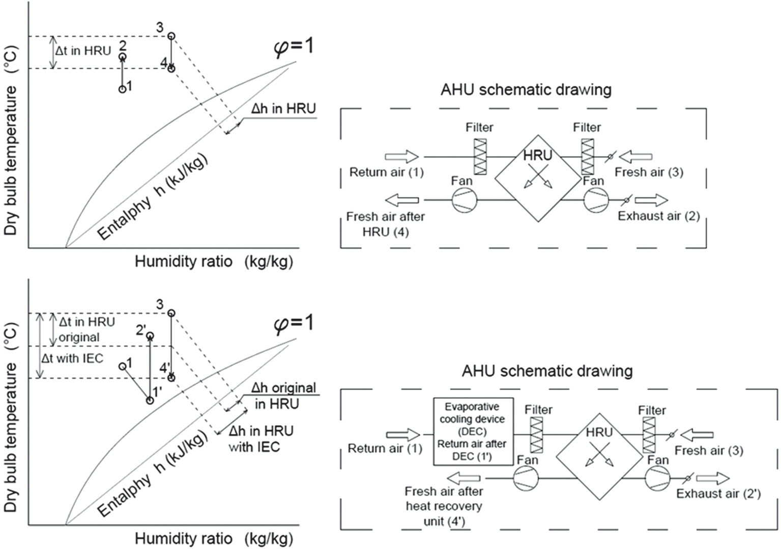
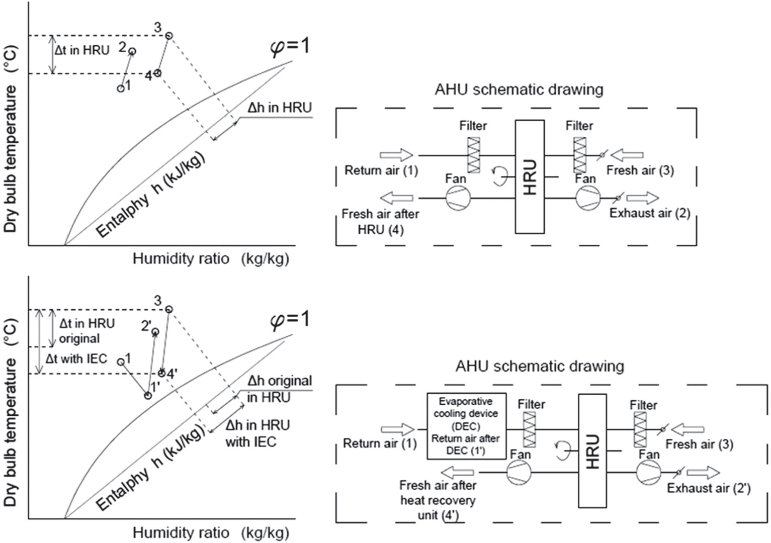
If the heat recovery unit preforms only heat transfer, the state change presented in Fig. 1 arises (typically involving coil heat exchangers, cross-flow exchangers) (Wallin and Claesson 2014). In this scenario, during the heat recovery process, the absolute moisture content of the air remains constant if the temperatures of the media exceed the condensation temperature. In such cases, the moisture transfer effectiveness is 0. For this form of heat recovery, the specific cooling performance of the IEC can be calculated simply. If moisture transfer occurs during the heat recovery process (Fig. 2), the moisture content of the medium in the HRU changes, which modifies the direction of the state change within the HRU. In the case of the IEC procedure, the extracted air is adiabatically cooled, leading to a decrease in air temperature and an increase in moisture content. Therefore, the application of the dry-coil IEC procedure in a heat recovery unit capable of mass transfer has a significant impact not only on the magnitude but also on the direction of the state change occurring in the heat recovery, which must be considered in calculations. The temperature decrease can be estimated, as a function of the evaporated water quantity, according to the following equation:
(3)
The variation in absolute moisture content of the air influences the state change within the heat recovery unit and the magnitude of the enthalpy change generated by the procedure (Figs. 1 and 2). In evaporative cooling processes, the creation of a large free water surface can be achieved through high pressure water atomization or the use of a cooling pad (Tejero-González and Franco-Salas 2021). In the investigation, a cellulose cooling pad was employed (Aolan 5,090 with a thickness of 10 cm). The humidification efficiency can be determined based on the following equation:
(4)
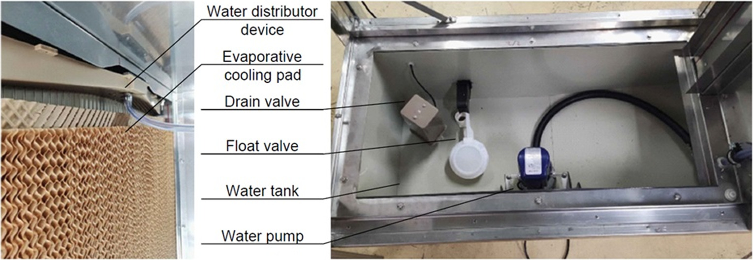
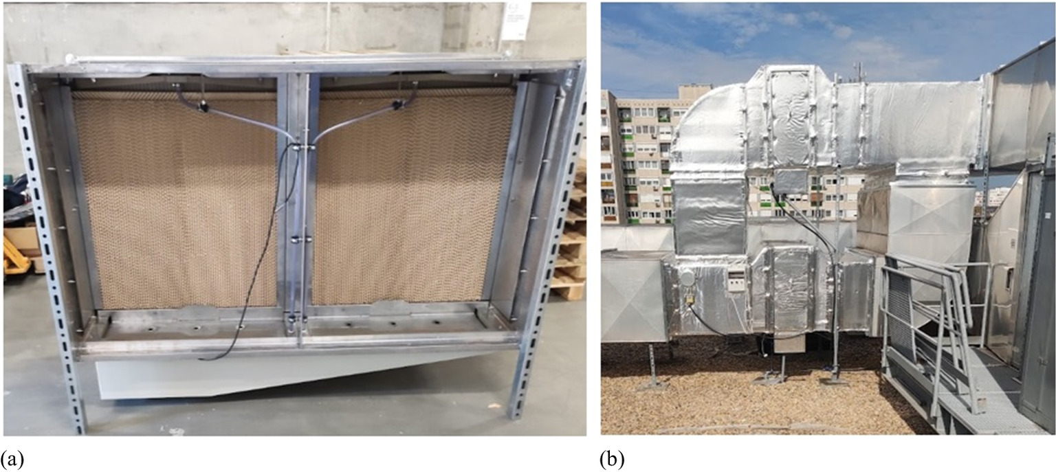
The evaporative cooling unit constructed by us consists of a water tank equipped with a float valve and a pump (Fig. 3). The pump delivers water from the tank to the top of the evaporative panel, ensuring its continuous wetness. Any excess water delivered to the panel overflows through the evaporative panel and returns to the tank. Due to evaporation, the water level in the tank gradually decreases. In response to the decreasing water level, the float valve opens, maintaining a constant water level in the tank. The quality of water has an impact on the lifespan of the cooling panel, and from a hygiene perspective, it is also beneficial to use desalinated water. However, this requires additional energy investment (Shahzad, et al. 2017).
Methods
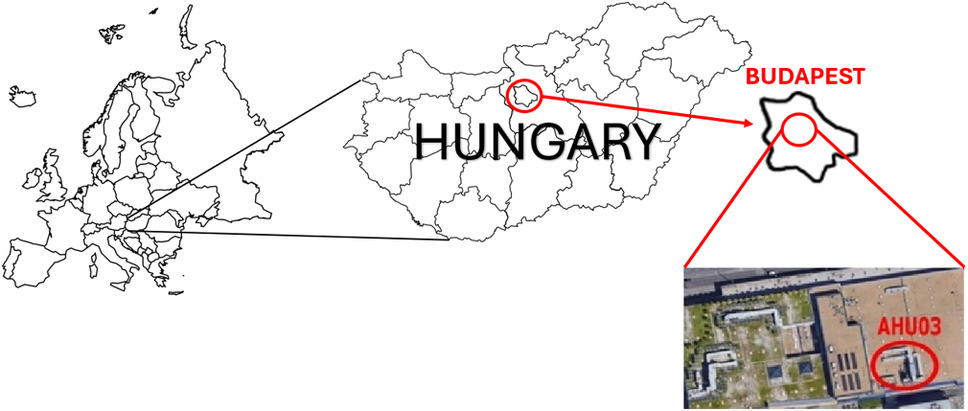
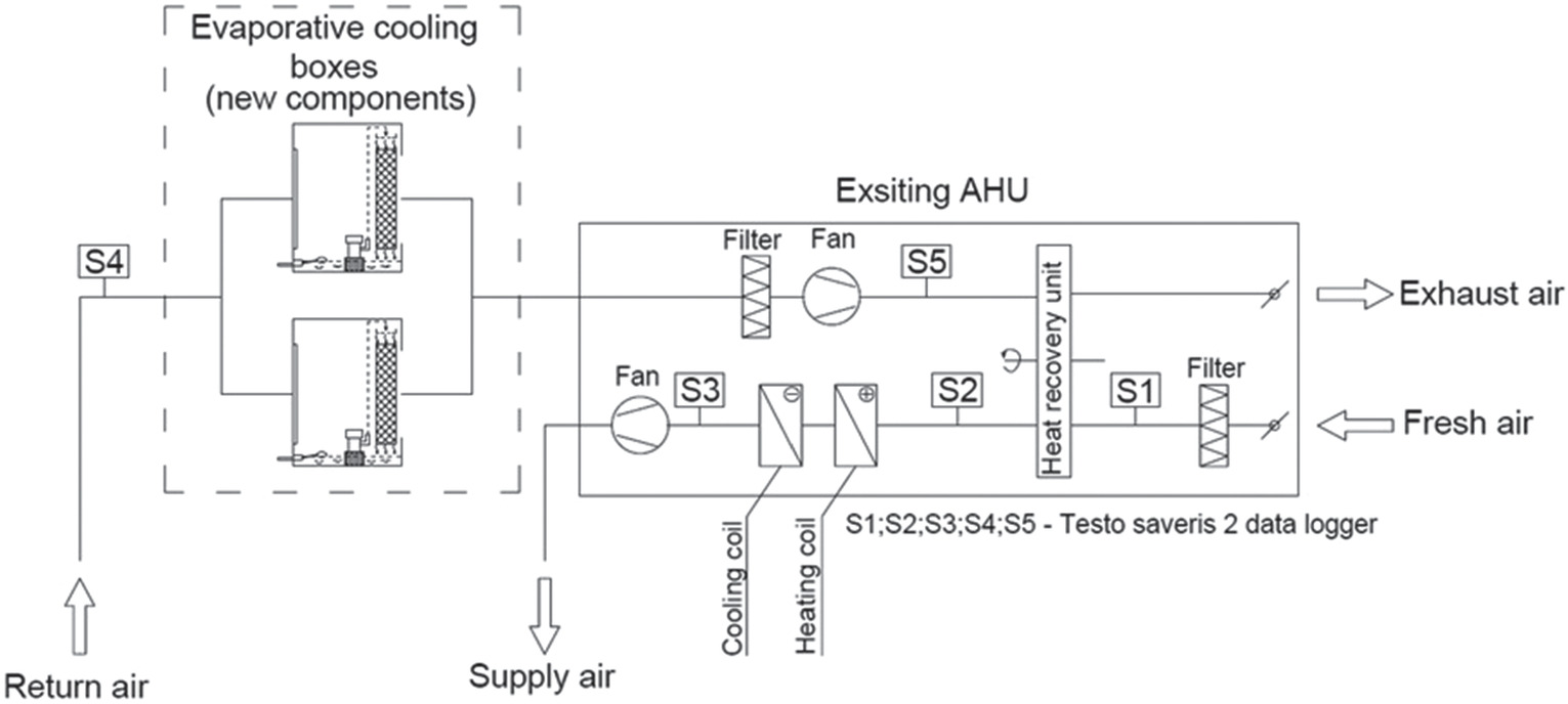
Indirect evaporative cooling methods have been previously examined under laboratory conditions (Kostyák et al. 2023). The purpose of the study presented in this paper is twofold. First, it aims to investigate how the IEC procedure influences the cooling energy utilized by the air handling equipment and whether it is worthwhile to design new air handlers incorporating the IEC procedure in the examined region. Additionally, our investigation explores whether it is worthwhile to retrospectively apply the IEC procedure in the renovation of existing equipment. In this study, the procedure was investigated under actual operating conditions. The examination took place at the IKEA shopping center in Örs Vezér Square, where the air handling unit designated as AHU-03 underwent modification. The shopping center is in the city center of Budapest, Hungary, in Central Europe (Fig. 4). This region experiences a continental climate with distinct seasons and significant temperature variations throughout the year. The summers are usually hot and dry, with occasional heatwaves. The average temperatures range from 25°C to 30°C, but can sometimes exceed 35°C. The operational characteristics of the procedure are presented based on results obtained during a torrid day, a hot day, and a summer day. The definitions of the aforementioned categories are presented in Table 1. The operation of the modified AHU will be presented over three consecutive days (August 6–8, 2022). The selected days represent the conclusion of a heatwave, featuring a torrid day (August 6, 2022), a hot day (August 7, 2022), and a summer day (August 8, 2022). The air handling unit is responsible for servicing the office and cashier zones. Its task involves supplying fresh air and the required heating or cooling energy to the occupied zones. During the summer season, the air introduced by the air handler provides a significant portion of the perceptible cooling performance. The set minimum supply air temperature limit is 16°C, as controlled by the BMS. Additional cooling energy input in the office area is provided by climate beams, while in the cashier area, fan coils take care of the supplementary cooling. The existing air handling unit has a nominal air volume flow rate of 40,000 m3/h. During actual operation, the extracted air volume is lower than the supplied air volume (approximately 28–30,000 m3/h), resulting in a slight positive pressure in the treated areas. The air handler does not have a recirculation branch, and the treated, supplied air is 100% fresh air. The effect of the differentiated extraction and supply had to be considered in the calculations. The air handling unit is equipped with a rotary heat recovery unit. The rotary heat recovery device employed in the air handler is capable of mass transfer, which must be taken into account in the calculations. In the calculation of the coefficient of performance (COP), the enthalpy change in the HRU must be taken into account [Eq. (5)] to avoid the inaccuracy caused by the latent heat, as follows:
(5)
| Day categories | Maximum temperature on the correlated day |
|---|---|
| Summer day | Tmax > 25°C |
| Hot day | Tmax ≥ 30°C |
| Torrid day | Tmax ≥ 35°C |
Source: Data from HMS (2022).
The required data for calculating the COP value are presented in Table 2. In this study, the enthalpy change that could be achieved if no mass transfer occurs during heat recovery (typically with coil heat exchangers, cross-flow exchangers) at the same heat recovery effectiveness was simulated. We placed an indirect evaporative cooling unit, created by us, in the duct network before the air handling unit (Appendix). During the study, our objective was to examine the reduction in mechanical cooling power demand achievable by modifying an existing air handling unit under real operational conditions. In the evaporative cooling unit, two Aolan 5090 cellulose evaporative panels were installed (Fig. 5). In addition, within the duct system, two independent evaporative cooling boxes were positioned. This setup allows us to investigate the impact of different water dosing procedures on humidification efficiency and the required water quantity for the operation of the technology in subsequent analyses. The exhaust-side temperature sensor of the air handling unit was positioned in front of the evaporative cooling unit, ensuring that the control of the air handler was not influenced by the DEC. The evaporative cooling units were equipped with independent control, responsible for circulating and refreshing water, in a manner consistent with industrial evaporative air coolers available on the market. During sizing, efforts were made to maintain nearly equal resistance in the replaced duct section as the integrated system elements, achieved by increasing the flow cross-sectional area.
| Main components | Properties |
|---|---|
| Supply side fan (SSF) | Nominal volume flow rate: 40.000 m3/h Total pressure rise: 1,107 Pa Efficiency, total: 75% |
| Exhaust side fan (ESF) | Nominal volume flow rate: 40.000 m3/h Real volume flow rate: 30.000 m3/h Total pressure rise: 908 Pa Efficiency, total: 69.8% |
| Evaporative cooling box (ECB) | Nominal electric performance of water pump: 40 W (2 pc) Total pressure drop: 82 Pa |
| Heat recovery unit (HRU) | Electric performance of motor for rotation: 750 W Pressure drop supply air side: 103 Pa Pressure drop return air side: 59 Pa |
Instruments
The air handling unit is equipped with Siemens automation sensors that provide data to the BMS regarding the AHU operation. During measurements, the Testo Saveris 2 data acquisition system was utilized. The data acquisition units are equipped with temperature and humidity sensors, allowing the instrument to calculate the condensation temperature and absolute moisture content. The data loggers were strategically placed in the duct system and the air handling unit (Fig. 6).
The parameters of the employed instruments are provided in Table 3. When evaluating the results, the measurement error of the instruments must be taken into account. A significant portion of the calculations is based on the difference between the results measured by the two instruments placed at different locations. These values can be interpreted by considering the combined error limit of the two instruments (2 times β). The data loggers connected to the Testo cloud system via Wi-Fi, enabling real-time monitoring of the data during operation. The AHU system adjusted the desired supplied air temperature based on the signal of the extracted air temperature. The heat and humidity sensor transmitter for the extracted air was positioned in front of the DEC units. Consequently, the transformation did not affect the control of the air handler. Based on the measured data, the parameters provided in Table 4 were calculated.
| Measuring instruments | Measured parameter | Range | Accuracy | Resolution |
|---|---|---|---|---|
| Hygrothermometer (Testo Saveris 2 H1) | Temperature Relative humidity | −30°C+… + 50°C 0%…100%RH | ±0.5°C ±2%RH | 0.1°C 0.1% |
| Digital differential pressure manometer (Testo 400) | Pressure drop | −100+… + 200 hPa | ± 0.3 Pa | 0.001 hPa |
| Calculated values | Equations used for the calculations |
|---|---|
| Specific enthalpy of the air | h = cp,a × ta + xa × (r + cp,v × ta)(kJ/kg) |
| Specific enthalpy change by HRU | ΔhHRU = h1 − h2 (kJ/kg) |
| Specific enthalpy change in AHU | |
| Temperature decreasing by DEC unit | |
| Specific mass flow of evaporated water | ΔxDEC = x4 − x5(kg/kg) |
| Thermal efficiency of HRU | |
| Moisture transfer efficiency of HRU | |
| Evaporative efficiency of DEC unit |
Based on the measured data during the operation of the AHU, it can be estimated what specific cooling performance the HRU within the air handler would have been capable of delivering without indirect evaporative cooling, assuming the thermal efficiency and moisture transfer efficiency of the HRU are consistent with the measured data. In order to examine the simulated operation, calculations according to Table 5 need to be performed. In this study, a third scenario is also examined and simulated, assuming that no moisture transfer occurs in the HRU. While keeping all other factors constant, it can be simulated how much the cooling performance would have changed if an equally thermal efficient cross-flow or counter-flow heat exchanger had been installed in the air handler. In this case, the state change occurs in the HRU as can be seen in the diagram in Fig. 1. The calculations necessary for the simulation are presented in Table 6. The measurements were conducted between August 5 and 9, 2022, and from August 11 to 17, 2022. The measurement results were recorded in 5-min intervals. During this period, the shopping center operated under normal conditions. Throughout the investigation, summer, hot, and torrid days were observed. Additionally, measurements were conducted on warm, dry, and rainy days. In the following sections, the results and conclusions drawn from selected days within the study period are presented.
| Calculated values | Equations used for the calculations |
|---|---|
| Air temperature of the fresh air after HRU | |
| Specific water vapor in the fresh air after HRU | x2 = x1 − ηx × (x1 − x4)(kg/kg) |
| Specific enthalpy of the fresh air after HRU | h2 = cp,a × t2 + x2 × (r + cp,v × t2)(kJ/kg) |
| Specific enthalpy change by HRU | ΔhHRU = h1 − h2 (kJ/kg) |
| Calculated values | Equations used for the calculations |
|---|---|
| Air temperature of the fresh air after HRU | |
| Specific water vapor in the fresh air after HRU | x2 = x1(kg/kg) |
| Specific enthalpy of the fresh air after HRU | h2 = cp,a × t2 + x1 × (r + cp,v × t2)(kJ/kg) |
| Specific enthalpy change by HRU | ΔhHRU = h1 − h2 (kJ/kg) |
Results and Discussion
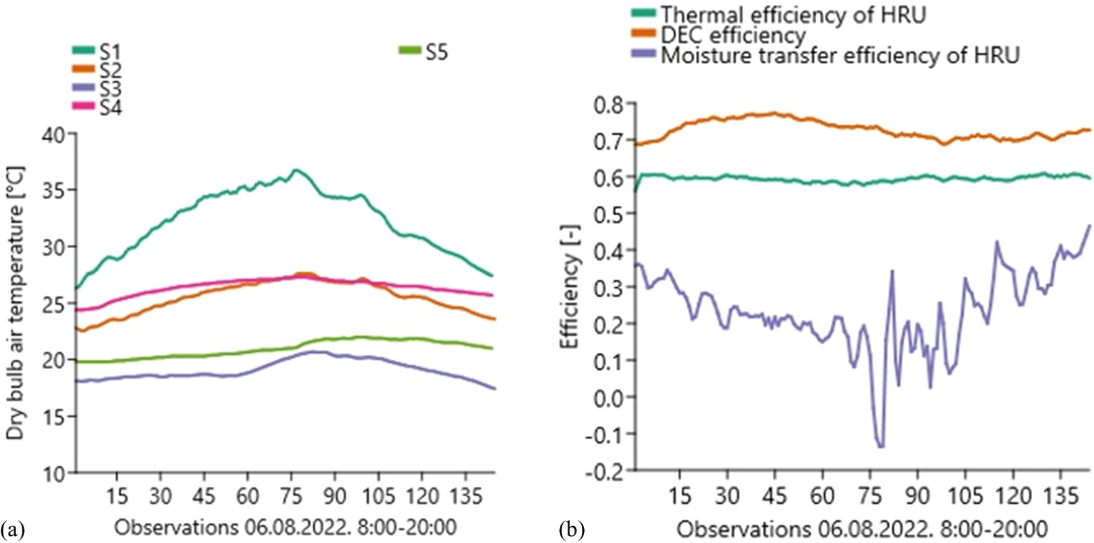
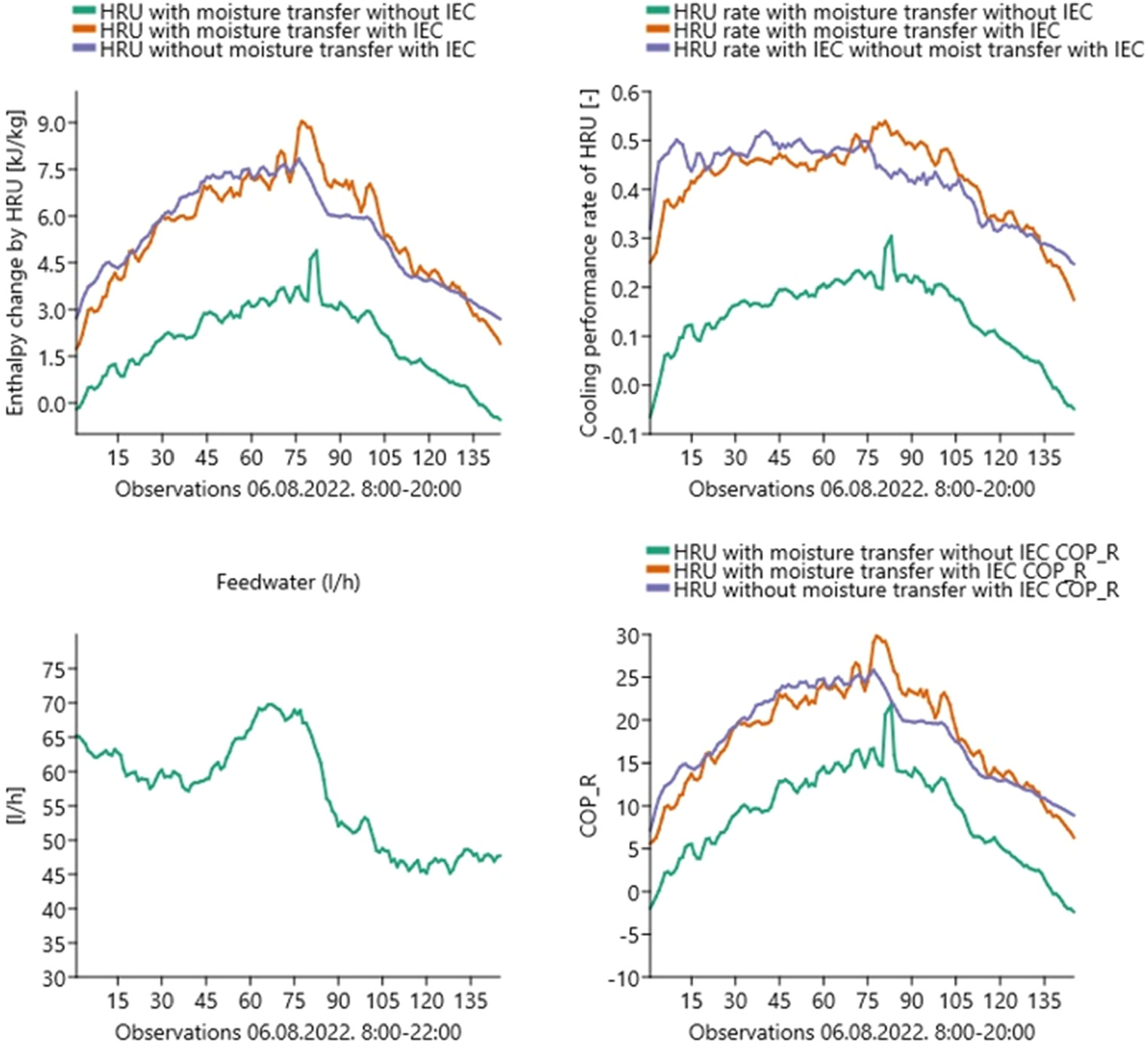
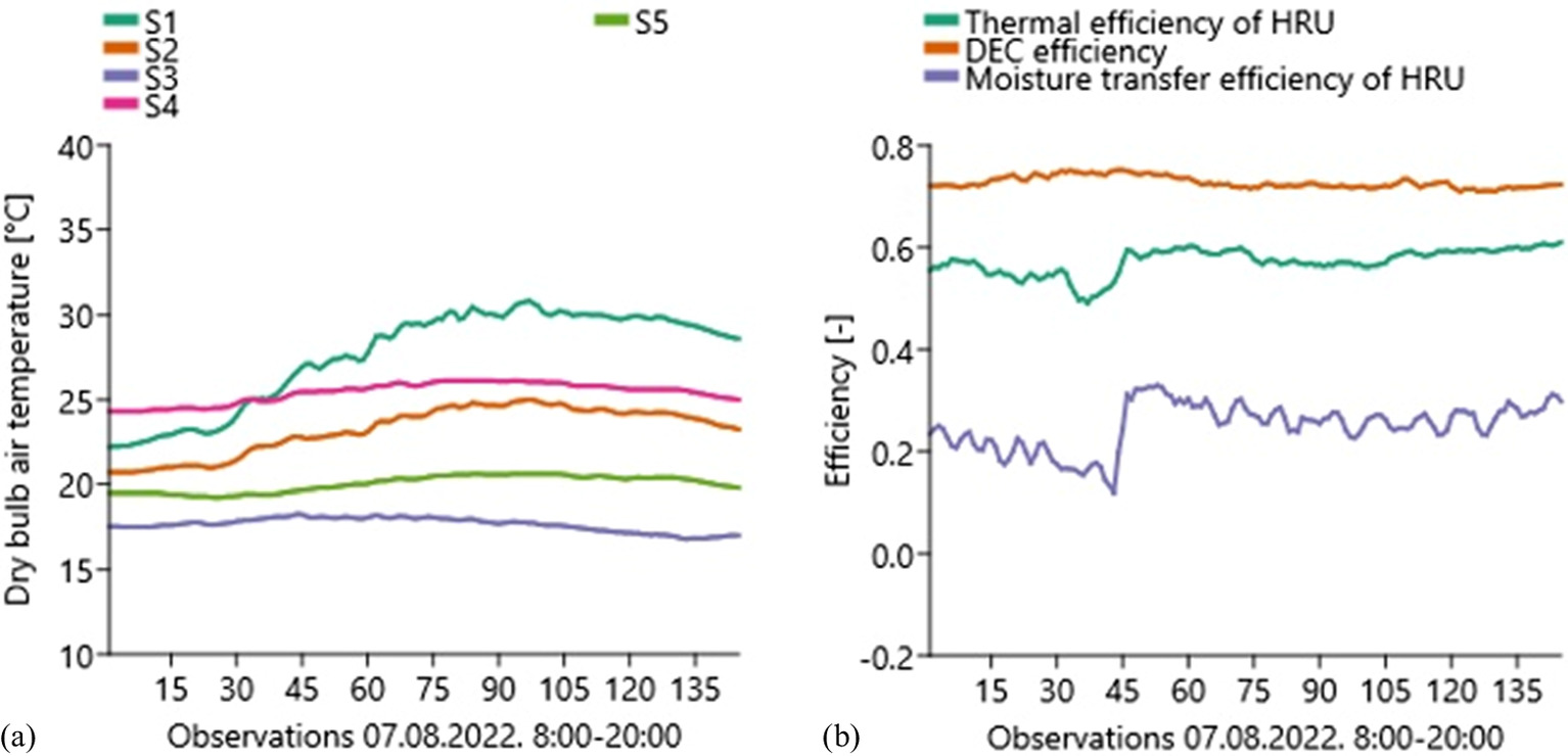
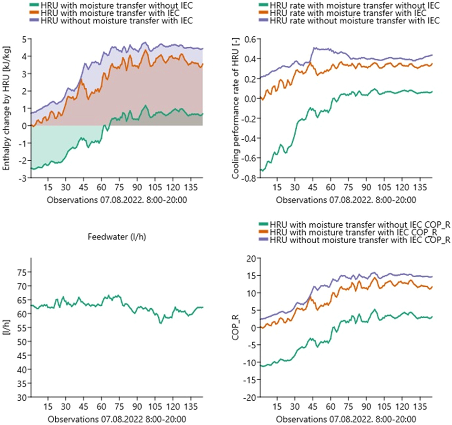
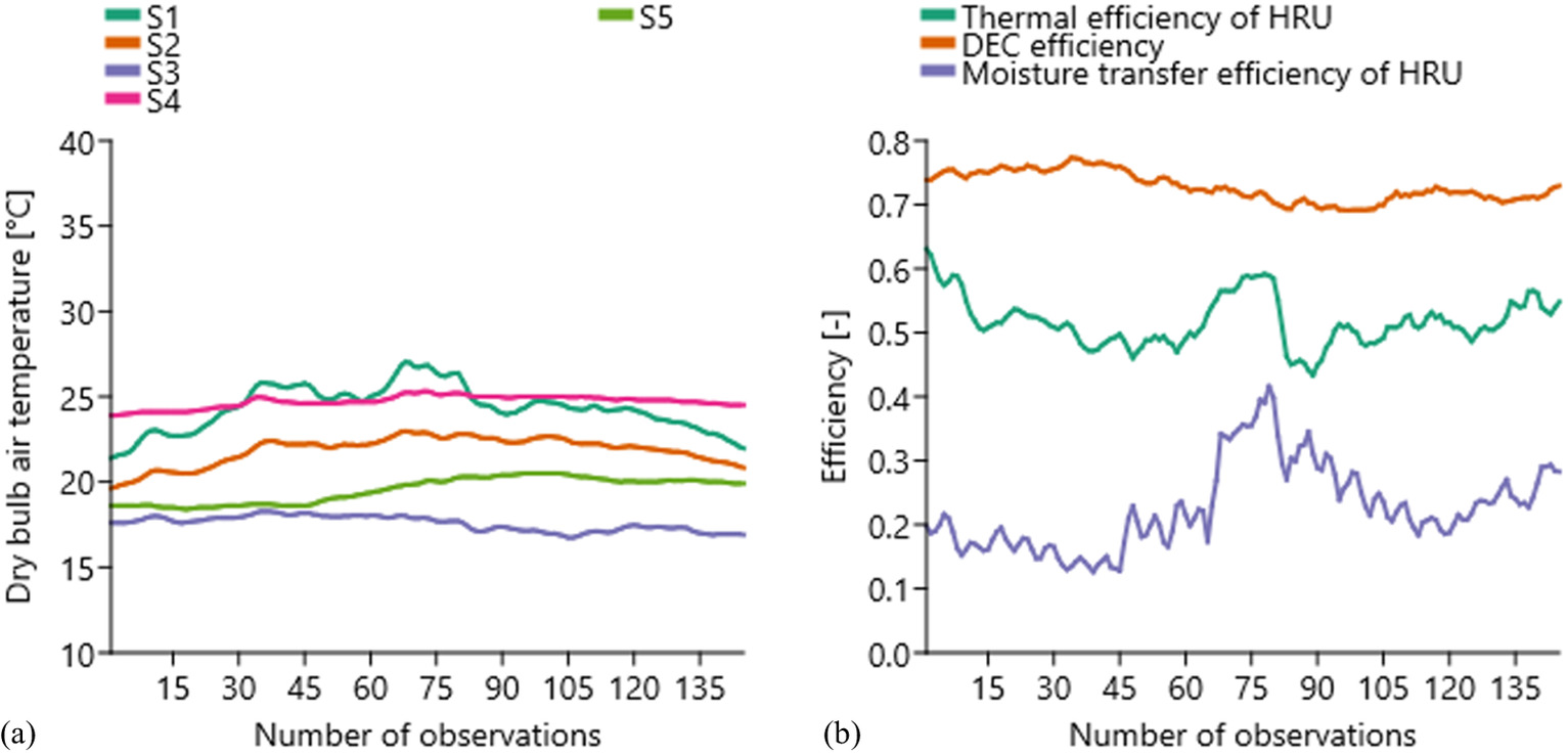
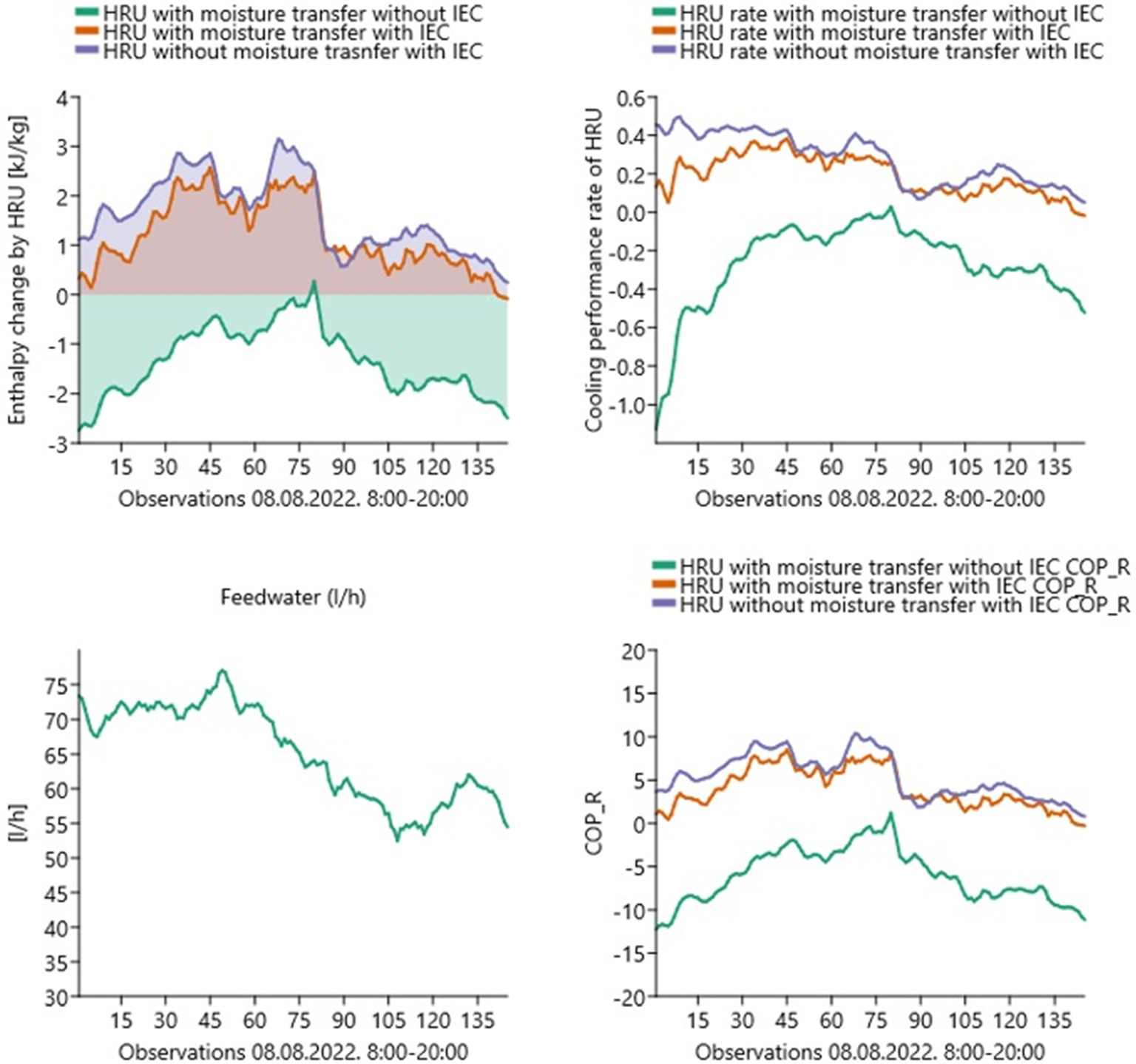
According to Table 7, it can be observed that the thermal efficiency of the HRU lags the requirements of modern ERP-compliant equipment [Commission Regulation (EU) No. 1253/2014, EU 2014]. The volatility of the HRU’s thermal efficiency value was low. However, the moisture transfer efficiency of the HRU exhibited significant volatility. Based on the investigations, high volatility was experienced when there was a small difference between the absolute moisture content of the extracted air undergoing the DEC procedure and the outdoor fresh air. In such cases, measurement errors significantly influenced the results, particularly during the measurements on August 6, 2022. The measured, calculated, and simulated data are presented in Table 8. The DEC efficiency showed only minor variations throughout the entire measurement series, with no significant fluctuations. On the torrid day (August 6, 2022, from 8:00 to 20:00), the temperature of the air extracted from the interior ranged from 24.4°C to 27.3°C, while the outdoor air temperature varied between 26.3°C and 36.9°C. These outdoor conditions closely align with the sizing temperatures commonly used in the region. Due to the DEC, the temperature of the air extracted from the interior decreased by 4.5°C–6.5°C, resulting in an increased cooling capacity extractable by the HRU [Fig. 7(a)]. Throughout the examined day, after the IEC procedure, the difference between the treated fresh air temperature and the indoor air temperature ranged from 0.4°C to 2.1°C. This indicates that, for a significant portion of the observed day, the IEC procedure allowed for a slightly lower supply temperature compared with the indoor air temperature when used independently. Based on the aforementioned, it can be concluded that when the IEC procedure is applied independently under the mentioned operational conditions, an air temperature lower than the indoor temperature can be achieved. This means that, by using the IEC procedure independently, a noticeable cooling performance can be introduced into the indoor environment. If the building has a separate cooling system to handle the indoor heat and moisture load, the air handling unit’s independent application of the IEC, without additional mechanical cooling, is conceivable. This system configuration is completely different from the general HVAC solutions commonly used in the region. With the air handling unit during the measurement, a significant amount of perceptible cooling performance is introduced into the occupied zone. The supply air temperature ranged from 17.5°C to 20.7°C, indicating that the AHU had a substantial mechanical cooling demand after the IEC procedure to achieve the desired supply air condition. By applying the IEC procedure, the cooling ratio of the HRU significantly increased compared with the traditional heat recovery mode. The total amount of cooling energy extractable by the HRU increased by 178% on the examined day (Fig. 8). In Fig. 8, a simulated scenario is illustrated where the HRU operates with the same thermal efficiency but without moisture transfer. During periods when the absolute humidity of the outdoor air exceeded that of the extracted air undergoing the DEC procedure, the HRU capable of moisture transfer yielded higher extractable cooling performance. Conversely, in the absence of moisture transfer with the HRU, a greater enthalpy change can be achieved. Based on the aforementioned, the relationship between indoor and outdoor humidity significantly influences the estimation of which heat recovery solution is more advantageous for maximizing the achievable enthalpy change by the HRU. While on the days examined so far, the outdoor air temperature always exceeded the indoor air temperature, during the period examined on August 7, 2022, from 8:00 to 20:00 (measured, calculated, and simulated data are presented in Table 9), the outdoor air temperature was lower than the indoor air temperature in the first half of the period (Fig. 9). During this time, cooling performance cannot be achieved with the application of the traditional heat recovery procedure. According to the graph in Fig. 10, when applying traditional heat recovery, a positive enthalpy change was achieved with the HRU only well after the outdoor air temperature exceeded the indoor air temperature. The reason for this is moisture transfer. The absolute humidity of the indoor air exceeded that of the outdoor air, reducing the enthalpy change occurring in the HRU because of the transferred moisture. If the control of the AHU is based only on temperature signals, the comparison of Figs. 9(a) and 10 shows that in the case of heat recovery without IEC, the HRU receives an operating signal even when the enthalpy of the treated supply air increases during its operation (since the indoor temperature is lower than the outdoor temperature). This results in an increase in the demand for mechanical cooling performance, rather than a decrease. The conclusion drawn from the aforementioned is that the control of the HRU and its bypass branch (if present) can only be based on temperature signals when moisture transfer does not occur during heat recovery. If moisture transfer occurs during heat recovery, proper operation can only be achieved by controlling based on enthalpy changes. Based on Fig. 10, it can be observed that the useful operating time of the HRU can be significantly increased by using the IEC procedure. During the observed period on August 7, 2022, the useful operating time of the HRU increased by 41%. The simulation shows that under the observed operating conditions on that day, the enthalpy change achievable without moisture transfer is significantly higher. In the case of rotary heat recovery units, a bypass branch is often not employed. When heat recovery does not occur, the rotor comes to a standstill. This solution results in continuous resistance and additional ventilation work. The addition of a bypass branch to rotary heat recovery units is one area of development that can reduce ventilation work (Zmrhal 2023). Based on the aforementioned results, it can be ascertained that the application of the IEC procedure can increase the useful operating time of the heat exchanger, thereby also reducing the extent of futile ventilation work generated by the resistance of the inactive heat exchanger. The increase in the useful operating time of the HRU is most prominently evident on the summer day of August 8, 2022 (measured, calculated, and simulated data are presented in Table 10). On that particular day, the external air temperature closely matched the indoor air temperature (Fig. 11). While in a conventional scenario the HRU would not have been able to reduce the demand for mechanical cooling on that day, with the IEC procedure, we were able to reduce the mechanical cooling power throughout the entire investigation period (Fig. 12). On a torrid day, it was observed that the application of the IEC procedure significantly reduces the planned capacity of mechanical cooling, while the examination of hot and summer days shows that the useful operating time of the heat recovery unit in the cooling mode can be significantly reduced. This reduction is achieved with minimal changes required in both the control and technical design of the AHU. The presented procedure is well applicable within the retrofit program of existing AHUs. It is important to note that during the measurements, the control of the AHU did not deactivate the HRU, even when it would have been justified based on the relationship between outdoor and indoor air conditions. This issue was reported to the operations department.
| Date and time interval | Efficiencies | Efficiency values |
|---|---|---|
| August 6, 2022, 8:00–20:00 | Thermal efficiency of HRU | 0.54–0.61 |
| Moisture transfer efficiency of HRU | −0.23 to 0.75 | |
| DEC efficiency | 0.69–0.77 | |
| August 7, 2022, 8:00–20:00 | Thermal efficiency of HRU | 0.48–0.61 |
| Moisture transfer efficiency of HRU | 0.11–0.34 | |
| DEC efficiency | 0.71–0.75 | |
| August 8, 2022, 8:00–20:00 | Thermal efficiency of HRU | 0.43–0.63 |
| Moisture transfer efficiency of HRU | 0.11–0.44 | |
| DEC efficiency | 0.69–0.77 |
| Parameter | Min. | Max. | Avg. |
|---|---|---|---|
| Measured temperature | |||
| Outside air temperature (S1) (°C) | 25.7 | 36.9 | 32.2 |
| Outside air after HRU air temperature (S2) (°C) | 22.4 | 27.6 | 25.5 |
| Supply air after AHU air temperature (S3) (°C) | 17.4 | 20.7 | 19.1 |
| Exhaust air temperature (S4) (°C) | 24.4 | 27.3 | 26.4 |
| Exhaust air after DEC air temperature (S5) (°C) | 19.6 | 22.0 | 20.9 |
| Measured absolute humidity | |||
| Outside air absolute humidity (S1) (g/kg) | 9.1 | 13.9 | 11.4 |
| Outside air after HRU absolute humidity (S2) (g/kg) | 9.79 | 13.9 | 11.9 |
| Supply air after AHU absolute humidity (S3) (g/kg) | 9.6 | 13.2 | 11.4 |
| Exhaust air absolute humidity (S4) (g/kg) | 10.6 | 13.1 | 11.7 |
| Exhaust air after DEC absolute humidity (S5) (g/kg) | 12.4 | 14.4 | 13.3 |
| Calculated parameters | |||
| HRU average thermal efficiency (%) | — | — | 59.3 |
| HRU average moisture transfer efficiency (%) | — | — | 23.4 |
| DEC efficiency (daily average) (%) | — | — | 72.7 |
| Cooling performance rate of HRU with moisture transfer with IEC (%) | — | — | 41.6 |
| Enthalpy change by HRU with moisture transfer with IEC (kJ/kg) | — | — | 5.49 |
| COPR HRU with moisture transfer with IEC (−) | 5.39 | 31.06 | 26.18 |
| COPR HRU with moisture transfer without IEC (−) | −2.52 | 17.89 | 8.63 |
| COPR HRU without moisture transfer with IEC (−) | 6.53 | 26.18 | 18.00 |
| Hourly feedwater consumption (L/h) | 43.75 | 71.45 | 56.98 |
| Daily feedwater consumption (L/day) | — | — | 1,367,52 |
| Simulated parameters | |||
| Cooling performance rate of HRU with moisture transfer without IEC (%) | — | — | 14.1 |
| Cooling performance rate of HRU without moisture transfer with IEC (%) | — | — | 42.2 |
| Enthalpy change by HRU without moisture transfer with IEC (kJ/kg) | — | — | 5.48 |
| Enthalpy change by HRU with moisture transfer without IEC (kJ/kg) | — | — | 1.97 |
| Parameter | Min. | Max. | Avg. |
|---|---|---|---|
| Measured temperature | |||
| Outside air temperature (S1) (°C) | 22.2 | 30.9 | 27.6 |
| Outside air after HRU air temperature (S2) (°C) | 20.7 | 25.0 | 23.2 |
| Supply air after AHU air temperature (S3) (°C) | 16.8 | 18.3 | 17.7 |
| Exhaust air temperature (S4) (°C) | 24.3 | 26.1 | 25.4 |
| Exhaust air after DEC air temperature (S5) (°C) | 19.2 | 20.6 | 20.0 |
| Measured absolute humidity | |||
| Outside air absolute humidity (S1) (g/kg) | 8.9 | 10.6 | 9.7 |
| Outside air after HRU absolute humidity (S2) (g/kg) | 9.3 | 11.1 | 10.4 |
| Supply air after AHU absolute humidity (S3) (g/kg) | 9.2 | 10.7 | 10.2 |
| Exhaust air absolute humidity (S4) (g/kg) | 10.2 | 11.3 | 10.8 |
| Exhaust air after DEC absolute humidity (S5) (g/kg) | 11.9 | 12.9 | 12.5 |
| Calculated parameters | |||
| HRU average thermal efficiency (%) | — | — | 57.3 |
| HRU average moisture transfer efficiency (%) | — | — | 25.0 |
| DEC efficiency (daily average) (%) | — | — | 72.7 |
| Cooling performance rate of HRU with moisture transfer with IEC (%) | — | — | 27.5 |
| Enthalpy change by HRU with moisture transfer with IEC (kJ/kg) | — | — | 2.62 |
| COPR HRU with moisture transfer with IEC (−) | −1.29 | 5.68 | −1.49 |
| COPR HRU with moisture transfer without IEC (−) | −0.26 | 14.93 | 8.65 |
| COPR HRU without moisture transfer with IEC (−) | 2.35 | 16.02 | 11.46 |
| Hourly feedwater consumption (L/h) | 55.86 | 68.17 | 62.38 |
| Daily feedwater consumption (L/day) | — | — | 1,497,12 |
| Simulated parameters | |||
| Cooling performance rate of HRU with moisture transfer without IEC (%) | — | — | 12.0 |
| Cooling performance rate of HRU without moisture transfer with IEC (%) | — | — | 38.9 |
| Enthalpy change by HRU without moisture transfer with IEC (kJ/kg) | — | — | 3.47 |
| Enthalpy change by HRU with moisture transfer without IEC (kJ/kg) | — | — | −0.33 |
| Parameter | Min. | Max. | Avg. |
|---|---|---|---|
| Measured temperature | |||
| Outside air temperature (S1) (°C) | 22.2 | 30.9 | 27.6 |
| Outside air after HRU air temperature (S2) (°C) | 20.7 | 25.0 | 23.2 |
| Supply air after AHU air temperature (S3) (°C) | 16.8 | 18.3 | 17.7 |
| Exhaust air temperature (S4) (°C) | 24.3 | 26.1 | 25.4 |
| Exhaust air after DEC air temperature (S5) (°C) | 19.2 | 20.6 | 20.0 |
| Measured absolute humidity | |||
| Outside air absolute humidity (S1) (g/kg) | 8.9 | 10.6 | 9.7 |
| Outside air after HRU absolute humidity (S2) (g/kg) | 9.3 | 11.1 | 10.4 |
| Supply air after AHU absolute humidity (S3) (g/kg) | 9.2 | 10.7 | 10.2 |
| Exhaust air absolute humidity (S4) (g/kg) | 10.2 | 11.3 | 10.8 |
| Exhaust air after DEC absolute humidity (S5) (g/kg) | 11.9 | 12.9 | 12.5 |
| Calculated parameters | |||
| HRU average thermal efficiency (%) | — | — | 57.3 |
| HRU average moisture transfer efficiency (%) | — | — | 25.0 |
| DEC efficiency (daily average) (%) | — | — | 72.7 |
| Cooling performance rate of HRU with moisture transfer with IEC (%) | — | — | 12.0 |
| Enthalpy change by HRU with moisture transfer with IEC (kJ/kg) | — | — | 2.62 |
| COPR HRU with moisture transfer with IEC (−) | −11.29 | 5.68 | −1.49 |
| COPR HRU with moisture transfer without IEC (−) | −0.26 | 14.93 | 8.65 |
| COPR HRU without moisture transfer with IEC (−) | 2.35 | 16.02 | 11.46 |
| Hourly feedwater consumption (L/h) | 51.70 | 78.01 | 65.15 |
| Daily feedwater consumption (L/day) | — | — | 1,536.6 |
| Simulated parameters | |||
| Cooling performance rate of HRU with moisture transfer without IEC (%) | — | — | 27.5 |
| Cooling performance rate of HRU without moisture transfer with IEC (%) | — | — | 38.9 |
| Enthalpy change by HRU without moisture transfer with IEC (kJ/kg) | — | — | 3.47 |
| Enthalpy change by HRU with moisture transfer without IEC (kJ/kg) | — | — | −0.33 |
Simulation
Based on the results measured on the examined days and the calculations, we simulated the amount of extractable cooling energy and useful operating time with the help of the heat recovery unit, assuming the following:
1.
AHU supply volume flow rate is 40,000 m3/h continuously.
2.
The investigated daily working hours are from 8:00 to 20:00 (12 h).
3.
HRU control operates properly, meaning that if it is unable to extract cooling capacity, it stops.
Under the given conditions, three scenarios were examined. In the first case, the operation of the HRU without the IEC procedure on the designated days was simulated. In the second case, the results of the HRU and IEC operations were summarized based on the measured data. In the third scenario, the simulation analyzed how the HRU’s operation would have evolved with IEC application in the absence of moisture transfer during heat recovery. The results are presented in Table 11.
| Date | Scenarios | Useful operating hours of HRU (max.: 12 h) (h) | Generated cooling energy by HRU (kW·h/day) | Electric consumption of the process (kW·h/day) | Required feedwater (m3/day) |
|---|---|---|---|---|---|
| August 6, 2022 8:00–20:00 (torrid day) | HRU with moisture transfer without IEC | 11.16 | 318.33 | 35.76 | 0 |
| HRU with moisture transfer with IEC | 12.00 | 878.26 | 48.5 | 8.262 | |
| HRU without moisture transfer with IEC | 12.00 | 876.61 | 48.5 | 8.262 | |
| August 7, 2022 8:00–20:00 (hot day) | HRU with moisture transfer without IEC | 6.75 | 57.50 | 35.76 | 0 |
| HRU with moisture transfer with IEC | 11.75 | 422.59 | 48.5 | 9.044 | |
| HRU without moisture transfer with IEC | 12.00 | 559.31 | 48.5 | 9.044 | |
| August 8, 2022 8:00–20:00 (summer day) | HRU with moisture transfer without IEC | 0.33 | 0.95 | 35.76 | 0 |
| HRU with moisture transfer with IEC | 11.67 | 196.10 | 48.5 | 9.447 | |
| HRU without moisture transfer with IEC | 12.00 | 262.73 | 48.5 | 9.447 |
Based on simulations and the measured results, it can be observed that the application of IEC significantly increased the useful operating time of the HRU and the amount of extractable cooling energy. The use of IEC not only resulted in significant cooling performance enhancement on the torrid day (August 6, 2022) but also during the hot (August 7, 2022) and summer days (August 8, 2022). The application of the IEC procedure allows for a substantial extension of the useful operating time of the HRU. According to the investigations, a higher cooling performance can be achieved with the moisture transfer-free heat recovery procedure. If the design of the air handling equipment allows for the exclusion of elements supporting heat recovery during inactive periods, the excess electrical power caused by the process does not burden the inactive period. In this case, the coefficient of performance of refrigeration (COPR) limit can be determined according to Eq. (6). Based on the COPR limit, the consumed energy can be determined depending on whether the use of the IEC procedure or increasing the performance of the cooling system is more favorable. If the COPR of the mechanical cooling system exceeds the COPR limit, the use of the IEC cooling procedure is not recommended. Otherwise, reducing the energy demand of the mechanical cooling system with the IEC procedure is recommended
(6)
Conclusion
The aim of the study was to investigate the operational characteristics of the dry-coil IEC procedure examined under laboratory conditions in real-world settings as well. Based on the measured data of the modified AHU, various heat recovery modes were simulated to obtain a more comprehensive understanding of the possibilities of retroactively implementing the IEC procedure. The examination of retrofit installation is crucial for assessing the application of the procedure in Retrofit programs. The daily average efficiency of the applicated evaporative cooling was ranged between 72.7% and 72.8%. As a result, the air temperature extracted from the interior decreased by 4.5°C–6.5°C, leading to a boost in the cooling capacity that the HRU can deliver.
The results of the investigations were illustrated with a detailed presentation of individual summer, hot, and torrid days. These days were suitable for assessing the operating conditions of the air handling unit in states close to peak load, as well as under expected operating conditions during the cooling season and transitional periods.
Based on the examinations, the following conclusions can be drawn:
1.
The independent application of the IEC procedure allows for a noticeable cooling performance, providing an opportunity for the development of new HVAC system configurations.
2.
With the IEC procedure, the maximum mechanical cooling demand, as well as the mechanical cooling energy consumption during the cooling season, can be significantly reduced.
3.
The useful operating time of heat recovery devices can be substantially extended by the application of the IEC procedure.
4.
With the increase in useful operating time, the extra ventilation work generated in the case of rotary heat exchangers without a bypass branch is largely utilized for achieving cooling performance.
5.
If moisture transfer occurs in the heat exchanger, controlling based on temperature signals is not suitable from a cooling technology perspective. The control of the heat exchanger should be designed based on enthalpy change.
6.
In the calculation of the COP, the enthalpy change in the HRU must be taken into account to avoid the inaccuracy caused by the latent heat.
7.
The examined dry-coil IEC procedure can be effectively integrated into existing air handling systems, making its application possible in retrofit programs.
Future Plan
Currently, we are examining the possibilities of water usage and treatment in the case of dry-coil IEC application. The goal of the investigations is to minimize the amount of water required for technology operation and address the hygiene issues that may arise during the long-term operation of the procedure.
The presented research results convinced the shopping center to design the new air handling units with a factory-integrated IEC device. Our research team played a role in the design. In the future, our goal is to examine how the energy consumption of the new AHU units, with higher heat recovery efficiency and regulated forward water temperature of the cooling coils, compares with the presented measurement results.
Appendix. Modified Air Handling System
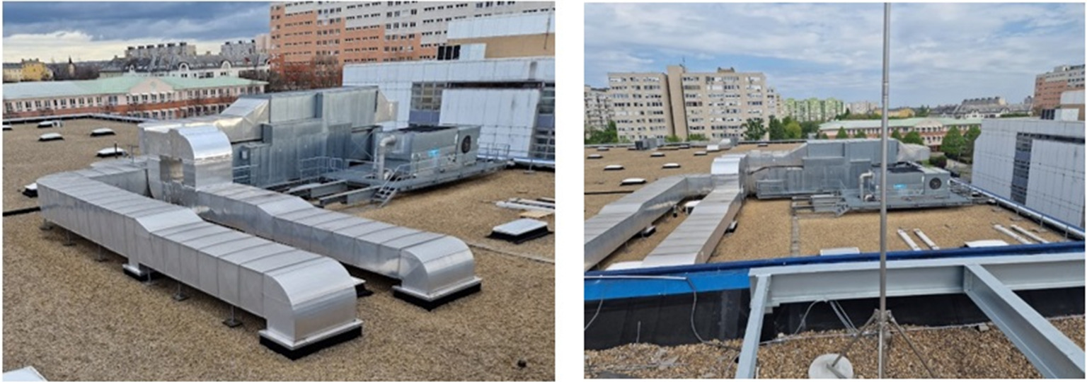
Fig. 13 shows the indirect evaporative cooling unit placed in the duct network before the air handling unit.
Data Availability Statement
Some or all data, models, or codes that support the findings of this study are available from the corresponding author upon reasonable request.
Acknowledgments
This study has been implemented with the support provided by the National Research, Development and Innovation Fund of Hungary (Project No. TKP2021-NKTA-34), financed under the TKP2021-NKTA funding scheme.
Author contributions: Attila Kostyák, Szabolcs Szekeres, and Imre Csáky: Conceptualization, Methodology, Software, Validation, Formal analysis, Investigation, Resources, Data curation, Writing—original draft preparation, Writing—review and editing, Visualization, Project administration, and Funding acquisition; I. Csáky: Supervision. All authors have read and agreed to the published version of the manuscript.
Notation
The following symbols are used in this paper:
- add. c
- value of the additional cooling system;
- cpa
- specific heat of the air at constant pressure (kJ kg−1K−1);
- cpv
- specific heat of the water vapor at constant pressure (kJ kg−1K−1);
- dehum
- dehumidification value;
- E
- cooling energy (kJ; kW·h);
- e
- after evaporative cooling;
- h
- enthalpy (kJ kg−1);
- i
- indoor;
- in
- input value;
- o
- outdoor;
- o
- limit of the outdoor value;
- out
- output value;
- out wb
- wet-bulb value of the output value;
- Q
- cooling performance (kW);
- r
- latent heat of vaporization (kJ kg−1);
- re
- before recovery unit, exhaust side;
- rs
- after recovery unit, supply side;
- s
- supply;
- sens
- sensible;
- T
- temperature (°C);
- Twb
- wet-bulb temperature (°C);
- tot
- total
- v
- water vapor;
- x
- extract;
- x
- humidity ratio of air (kgv/kga);
- Δ
- sum of differences (−);
- ɛ
- effectiveness of direct evaporative cooling (%); and
- η
- effectiveness of heat recovery unit (%).
References
Bishoyi, D., and K. Sudhakar. 2017. “Experimental performance of a direct evaporative cooler in composite climate of India.” Energy Build. 153: 190–200. https://doi.org/10.1016/j.enbuild.2017.08.014.
Chen, Q., J. M. Ja, M. Burhan, M. W. Shahzad, D. Ybyraiymkul, H. Zheng, and K. C. Ng. 2022. “Experimental study of a sustainable cooling process hybridizing indirect evaporative cooling and mechanical vapor compression.” Energy Rep. 8: 7945–7956. https://doi.org/10.1016/j.egyr.2022.06.019.
Chen, Y., and H. Yang. 2015. “Thermal performances comparison between dry-coil and wet-coil indirect evaporative cooler under the same configuration.” Energy Procedia 75: 3162–3167. https://doi.org/10.1016/j.egypro.2015.07.653.
Cho, H.-J., S.-Y. Cheon, and J.-W. Jeong. 2023. “Experimental analysis on energy recovery ventilator with latent heat exchanger using hollow fiber membrane.” Energy Convers. Manage. 278: 116706. https://doi.org/10.1016/j.enconman.2023.116706.
Doğramacı, P. A., and D. Aydın. 2020. “Comparative experimental investigation of novel organic materials for direct evaporative cooling applications in hot–dry climate.” J. Build. Eng. 30: 101240. https://doi.org/10.1016/j.jobe.2020.101240.
Duan, Z., C. Zhan, X. Zhang, M. Mustafa, X. Zhao, B. Alimohammadisagvand, and A. Hasan. 2012. “Indirect evaporative cooling: Past, present and future potentials.” Renewable Sustainable Energy Rev. 16 (9): 6823–6850. https://doi.org/10.1016/j.rser.2012.07.007.
EU (European Union). 2014. “Implementing Directive 2009/125/EC of the European Parliament and of the Council with regard to ecodesign requirements for ventilation units.” COMMISSION REGULATION (EU) No 1253/2014 of 7 July 2014. Accessed February 20, 2024. https://eur-lex.europa.eu/legal-content/EN/TXT/PDF/?uri=CELEX:32014R1253&from=PL.
Harrouz, J. P., K. Ghali, and N. Ghaddar. 2021. “Integrated solar—Windcatcher with dew-point indirect evaporative cooler for classrooms.” Appl. Therm. Eng. 188: 116654. https://doi.org/10.1016/j.applthermaleng.2021.116654.
HMS (Hungarian Meteorological Services). 2022. “Evaluation of (extreme) climate indices.” HungaroMet. Accessed June 18, 2022. http://www.met.hu/en/omsz/tevekenysegek/klimamodellezes/szelsosegek/.
Jamil, M. A., M. W. Shahzad, B. B. Xu, M. Imran, K. C. Ng, S. M. Zubair, C. N. Markides, and W. M. Worek. 2023. “Energy-efficient indirect evaporative cooler design framework: An experimental and numerical study.” Energy Convers. Manage. 292: 117377. https://doi.org/10.1016/j.enconman.2023.117377.
Kostyák, A., S. Szekeres, and I. Csáky. 2023. “Investigation of sensible cooling performance in the case of an air handling unit system with indirect evaporative cooling: Indirect evaporative cooling effects for the additional cooling system of buildings.” Buildings 13 (7): 1800. https://doi.org/10.3390/buildings13071800.
Krüger, E. L., and E. M. González Cruz. 2023. “Evolving from an indirect evaporative cooling system to a radiant-capacitive heating and cooling system for low-mass buildings.” J. Build. Eng. 79: 107880. https://doi.org/10.1016/j.jobe.2023.107880.
Liao, J., X. Xie, H. Nemer, D. E. Claridge, and C. H. Culp. 2019. “A simplified methodology to optimize the cooling tower approach temperature control schedule in a cooling system.” Energy Convers. Manage. 199: 111950. https://doi.org/10.1016/j.enconman.2019.111950.
Mardiana-Idayu, A., and S. B. Riffat. 2012. “Review on heat recovery technologies for building applications.” Renewable Sustainable Energy Rev. 16 (2): 1241–1255. https://doi.org/10.1016/j.rser.2011.09.026.
Papakostas, K. T., and A. M. Papadopoulos. 2004. “Energy requirements for the treatment of fresh air in HVAC systems: A case study for Athens and Thessaloniki, Greece.” Int. J. Vent. 3 (1): 33–39. https://doi.org/10.1080/14733315.2004.11683901.
Sajjad, U., N. Abbas, K. Hamid, S. Abbas, I. Hussain, S. M. Ammar, M. Sultan, H. M. Ali, M. Hussain, and C. C. Wang. 2021. “A review of recent advances in indirect evaporative cooling technology.” Int. Commun. Heat Mass Transfer 122: 105140. https://doi.org/10.1016/j.icheatmasstransfer.2021.105140.
Shahzad, M. W., M. Burhan, L. Ang, and K. C. Ng. 2017. “Energy-water-environment nexus underpinning future desalination sustainability.” Desalination 413: 52–64. https://doi.org/10.1016/j.desal.2017.03.009.
Shahzad, M. W., J. Lin, B. B. Xu, L. Dala, Q. Chen, M. Burhan, M. Sultan, W. Worek, and K. C. Ng. 2021. “A spatiotemporal indirect evaporative cooler enabled by transiently interceding water mist.” Energy 217: 119352. https://doi.org/10.1016/j.energy.2020.119352.
Shaikh, P. H., N. B. Nor, P. Nallagownden, I. Elamvazuthi, and T. Ibrahim. 2014. “A review on optimized control systems for building energy and comfort management of smart sustainable buildings.” Renewable Sustainable Energy Rev. 34: 409–429. https://doi.org/10.1016/j.rser.2014.03.027.
Shi, W., H. Yang, X. Ma, and X. Liu. 2023. “Techno-economic evaluation and environmental benefit of hybrid evaporative cooling system in hot-humid regions.” Sustain. Cities Soc. 97: 104735. https://doi.org/10.1016/j.scs.2023.104735.
Solano, J. C., E. Caamaño-Martín, L. Olivieri, and D. Almeida-Galárraga. 2021. “HVAC systems and thermal comfort in buildings climate control: An experimental case study.” Energy Rep. 7: 269–277. https://doi.org/10.1016/j.egyr.2021.06.045.
Tejero-González, A., and A. Franco-Salas. 2021. “Optimal operation of evaporative cooling pads: A review.” Renewable Sustainable Energy Rev. 151: 111632. https://doi.org/10.1016/j.rser.2021.111632.
Vakiloroaya, V., B. Samali, A. Fakhar, and K. Pishghadam. 2014. “A review of different strategies for HVAC energy saving.” Energy Convers. Manage. 77: 738–754. https://doi.org/10.1016/j.enconman.2013.10.023.
Wallin, J., and J. Claesson. 2014. “Improving heat recovery using retrofitted heat pump in air handling unit with energy wheel.” Appl. Therm. Eng. 62 (2): 823–829. https://doi.org/10.1016/j.applthermaleng.2013.09.059.
Wang, H., and Q. Chen. 2014. “Impact of climate change heating and cooling energy use in buildings in the United States.” Energy Build. 82: 428–436. https://doi.org/10.1016/j.enbuild.2014.07.034.
Yang, Y., G. Cui, and C. Q. Lan. 2019. “Developments in evaporative cooling and enhanced evaporative cooling—A review.” Renewable Sustainable Energy Rev. 113: 109230. https://doi.org/10.1016/j.rser.2019.06.037.
Zhivov, A. M., R. Lohse, R. J. Liesen, and O. C. Mørck. 2016. “Core bundles of technologies to achieve deep energy retrofit with major building renovation projects in Europe, the United States, and China.” ASHRAE Trans. 122, 22–43.
Zmrhal, V. 2023. “The energy saving potential of a rotary heat exchanger with bypass dampers.” Energy Build. 285: 112934. https://doi.org/10.1016/j.enbuild.2023.112934.
Information & Authors
Information
Published In

Journal of Architectural Engineering
Volume 30 • Issue 4 • December 2024
Copyright
This work is made available under the terms of the Creative Commons Attribution 4.0 International license, https://creativecommons.org/licenses/by/4.0/.
History
Received: Feb 27, 2024
Accepted: Apr 30, 2024
Published online: Jul 17, 2024
Published in print: Dec 1, 2024
Discussion open until: Dec 17, 2024
ASCE Technical Topics:
- Air temperature
- Case studies
- Construction engineering
- Construction methods
- Control systems
- Energy engineering
- Energy infrastructure
- Energy recovery
- Engineering fundamentals
- Engineering mechanics
- Evaporation
- Feasibility studies
- Hydrologic engineering
- Infrastructure
- Lifeline systems
- Material mechanics
- Material properties
- Materials engineering
- Methodology (by type)
- Rehabilitation
- Research methods (by type)
- Systems engineering
- Systems management
- Temperature (by type)
- Thermal properties
- Thermodynamics
- Water and water resources
Authors
Metrics & Citations
Metrics
Citations
Download citation
If you have the appropriate software installed, you can download article citation data to the citation manager of your choice. Simply select your manager software from the list below and click Download.