Abstract
Elastoplastic constitutive equations for soils often employ the nonlinear rate-type isotropic Hooke’s law, which is based on the additive decomposition of strain rate and considers the pressure dependency in the elastic part. Hooke’s law has independent isotropic and deviatoric components, and therefore, it cannot express elastic dilatancy as confirmed in experiments. In this model, although the elastic volume change is path-independent, the shear strain exhibits a significant residual when subjected to an effective stress cycle. This study proposes a rate-type elastic constitutive equation for soil applicable to elastoplastic constitutive equations based on finite deformation theory using an objective stress rate and additive decomposition of stretching; these equations cover these shortcomings of the rate-type Hooke’s law. The proposed rate-type elasticity constitutive equation is based on the hyperelastic body in the infinitesimal deformation theory proposed by Einav and Puzrin or Houlsby et al. and has confining pressure dependence, path independence of elastic volume change, and elastic dilatancy. Further, the residual strain is considerably smaller than that of the rate-type Hooke’s law. Moreover, this study improves the elasto-plastic constitutive equation, SYS Cam-Clay model, based on the skeleton structure concept by introducing the proposed elastic constitutive equation. The basic behavior of the elastoplastic constitutive equation for clay and sand is demonstrated to show that the newly acquired elastic dilatancy improves the mean effective stress reduction behavior during shear stress unloading under undrained conditions and the stiffness recovery behavior during liquefaction, which is essential for describing cyclic mobility.
Introduction
The rate-type isotropic Hooke’s law (Truesdell 1965) with constraining pressure dependence is widely applied for the elastic part of the elastoplastic constitutive models for soils, such as the Cam-Clay model, Drucker–Prager model, and their advanced forms. This nonlinear rate-type elastic constitutive equation has a simple structure and is compatible with the state boundary surface, which is an essential experimental fact in critical state soil mechanics (Schofield and Wroth 1968; Atkinson and Bransby 1978) because the elastic volume change is path-independent, although it is a hypoelastic constitutive equation. However, this rate-type elastic constitutive equation suffers from (1) the inability to represent elastic dilatancy as observed in the experiments (El-shoby 1969; Ohmaki 1979; Tafili and Triantafylidis 2019); and (2) significant residual deviator strain in response to stress cycles. One of the objectives of this study is to propose a rate-type elastic constitutive equation that mitigates/overcomes these problems while retaining the simplicity and path independence of the volume change exhibited by the confining pressure-dependent rate-type Hooke’s law.
Einav and Puzrin (2004) proposed a hyperelastic constitutive model for soils, considering the influence of confining pressure in the infinitesimal deformation theory. Houlsby et al. (2005) also proposed a hyperelastic constitutive model with similar properties. While the former model is derived from Gibbs free energy given as a function of stress, the latter is derived from Helmholtz free energy given as a function of the small strain. (The Helmholtz free energy of the latter model can be explicitly transformed into Gibbs free energy through Legendre transformation.) Although they have fundamentally different constitutive models, the material constants can be set such that the logarithmic volume strain and the logarithm of the mean effective stress have a linear relationship during isotropic compression, and both constitutive models are consistent under this setting. These models have been applied to elastoplastic models by many researchers (Golchin and Lashkari 2014); however, most of these efforts are within the framework of the infinitesimal deformation theory. This study derives a rate-type elastic constitutive model from the aforementioned hyperelastic models so that the model can apply to the finite-deformation elastoplastic theory that uses a corotational stress rate and additive decomposition of stretching.
In this study, the super-subloading yield surface Cam-Clay model, that is, the SYS Cam-Clay model, proposed by Asaoka et al. (2002), was selected as an elastoplastic constitutive model. This model is an extension of the Cam-Clay model (Roscoe et al. 1963; Schofield and Wroth 1968) developed for normally consolidated clays to be applied to a wider range of soils. The model introduces a superloading surface to describe the structural decay of naturally deposited soils (Asaoka et al. 1994, 2000 2002) and a subloading surface to represent the degradation of overconsolidation (Hashiguchi 1989; Asaoka et al. 1997). In addition, the model introduces rotational hardening (Hashiguchi and Chen 1998; Asaoka et al. 2002) to account for the induced anisotropy. This model aims to describe the behavior of sandy and clayey soils by varying the degradation rate of the structure and that of overconsolidation. However, the reproduction of the cyclic mobility seen during the liquefaction of sandy soils remains a challenge. One of the key reasons for this behavior is the decrease in mean effective stress during unloading under constant-volume conditions and the recovery of stiffness during liquefaction. For example, Hashiguchi and Mase (2010) and Hashiguchi et al. (2022) attempted to describe cyclic mobility using the Cam-Clay model with rotational hardening and an extended subloading surface; they reproduced the decrease in effective stress and the increase in strain amplitude because of liquefaction, but their simulation results do not capture the characteristics of the experimental results in terms of the mean effective stress remaining constant during unloading because their elastic constitutive equation was a pressure-dependent rate-type Hooke’s law. Zhang et al. (2007) attempted to solve this problem by flattening the shape of the yield surface and reducing the elastic range as the induced anisotropy develops. However, the development of induced anisotropy is suppressed in dense sand, where plastic deformation is less prone to occur; therefore, the mean effective stress remains constant during unloading, and thus, the effective stress path is not as close to the origin as that in experiments. There is a marked improvement in the effective stress path when loose sand is the target; however, there is a tradeoff of expressing the decrease in mean effective stress during undrained removing shear stress by plastic deformation. The stiffness during unloading is noticeably lower than in experiments. This paper demonstrates that the proposed rate-type elastic constitutive equation can play a valuable role in improving the effective stress path during undrained unloading without modifying the plastic part. [However, the authors do not claim that the introduction of the proposed rate-type elastic constitutive model provides a complete reproduction of cyclic mobility. The authors plan to reproduce cyclic mobility by introducing rotational hardening into the combined loading elastoplastic constitutive equation (Yamada et al. 2022a), wherein the SYS Cam-Clay and Drucker–Prager models work as a single model. In this case, the decrease in the mean effective stress during undrained unloading can be expressed by the elastic constitutive equation proposed in this paper.]
Definition of Various Quantities
In this section, the main variables used in this study are defined. The Cauchy stress tensor, defined as positive in tension, is expressed in terms of . The effective stress tensor is defined as , where u denotes the pore-water pressure defined as positive in compression and is the identity tensor. The invariants of are defined aswhere operator “·” = inner product of the tensor . A back-stress ratio (rotational-hardening variable tensor) is introduced to cater to the induced anisotropy by applying rotational hardening (Hashiguchi and Chen 1998). The invariants related to are defined as follows:where = invariant proposed by Sekiguchi and Ohta (1977); however, they supposed that was constant.
(1)
(2)
(3)
(4)
(5)
In this study, the following corotational rate presented by Green and Naghdi (1965) was used as the objective stress rate tensor so that the rate-type elastic constitutive equations and the elastoplastic constitutive equations that apply them satisfy the principle of material objectivitywhere = orthogonal tensor obtained by the polar decomposition of the deformation gradient tensor . The Green–Naghdi rate is used as an objective stress rate because it does not produce unnatural stress oscillations such as those caused by the Jaumann (1911) rate of Cauchy stress in simple shear (Dienes 1979).
(6)
Stretching tensor is defined as the symmetric part of the velocity gradient , and the invariants of are defined as follows:
(7)
(8)
Rate-Type Elastoplastic Constitutive Equation Considering the Skeleton Structure Concept
In this section, we will define a rate-type elastic constitutive model that takes into account the influence of confining pressure and elastic volume change induced by applying shear stress (elastic dilatancy, e.g., Tighe 2014) and introduce it into the SYS Cam-Clay model.
Additive Decomposition of Stretching and Logarithmic Volume Strain
Stretching is additively decomposed into elastic component and plastic component :
(9)
The time integration of Dv gives the logarithmic volume strain ɛv defined as positive in compression:where v( = 1 + e) denotes the specific volume (e is the void ratio), and v0 represents its initial value.
(10)
ɛv can be additively decomposed in the following two ways:
(11)
(12)
Therefore, the elastic and plastic logarithmic volume strains are defined by the time integration of and , respectively, and is determined so that the following equations are satisfied:
(13)
(14)
Rate-Type Elastic Constitutive Equations Considering the Influence of Constraining Pressure
The Gibbs free energy, proposed by Einav and Puzrin (2004) within the framework of infinitesimal deformation theory, is expressed as follows when the elastic reference stress state is chosen to be ( is a constant):where , , m, and n = material constants. Eq. (15) is expressed as follows in the limit of m = n = 1:
(15)
(16)
The elastic constitutive equation obtained by differentiating Eq. (16) by the stress is a straight line in the lnv − lnp′ plane in the isotropic compression. The elastic constitutive equation is rewritten in the rate form, and the following equation obtained by replacing the stress rate and strain rate with the objective stress rate and stretching, respectively, is accepted as a rate-type elastic constitutive equation:
(17)
The fourth-order tensor is the elastic tangent modulus and is expressed as follows:where ( )ijkl = δikδjl; ; and δij = Kronecker’s delta.
(18)
The same rate-type elastic constitutive model is also obtained as a special form of the hyperplastic constitutive model proposed by Houlsby et al. (2005).
This elastic constitutive model is formally consistent with the rate-type Hooke’s law in the isotropic stress state. In the isotropic stress state, and denote the shear and bulk elastic modulus, respectively. and can be expressed as follows:where represents a material constant that has the same meaning as the Poisson’s ratio in the isotropic stress state and is called the pseudo-Poisson’s ratio; and represents a material constant that denotes the slope of the swelling line in the lnv − lnp′ plane, which is called the swelling index.
(19)
The elastic logarithmic volume strain can be derived from Eq. (17). is derived from as follows:
(20)
The first term on the right-hand side is obtained by taking the trace of Eq. (17) as follows:
(21)
The second term on the right-hand side is obtained by taking the inner product of Eq. (17) with as follows:
(22)
The elastic constitutive model defined by Eq. (17) is a hypoelastic constitutive model. Therefore, the strain is essentially path-dependent with respect to stress history; however, Eq. (23) indicates that the volumetric strain is determined only from the initial and current stress states. It is important for the Cam-Clay model that the elastic volume change is independent of stress history because the model takes the plastic volume strain as the internal state variable. Eq. (23) satisfies this requirement. The second term on the most right-hand side of Eq. (23) indicates that the main difference between this law and the rate-type Hooke’s law is that shear stress causes elastic volume expansion.
From Eq. (13), if is not changed, and should maintain a constant value. Therefore, the surface that is drawn by Eq. (24) in p′ − q − v space under the constant- condition represents the range of states in which the combination of stress and specific volume would be possible if only elastic deformation was assumed to occur. This is called an elastic surface in this study; it corresponds to the elastic wall (Atkinson and Bransby 1978) obtained using a rate-type Hooke’s law as the elastic constitutive model.
Three Loading Surfaces Composed of the SYS Cam-Clay Model
The elastic constitutive model proposed in the previous section is applied to the SYS Cam-Clay model, which is based on the skeleton structure concept. The skeleton structure concept was first suggested by Mikasa (1959), who believed that the mechanical properties of soils are determined by the kind and state. He called factors other than density and water content as the skeleton structure among factors that determine the latter. In addition, Asaoka et al. (2002) considered the structure, overconsolidation, and anisotropy as independent factors in forming a skeleton structure for the development of an elastoplastic constitutive equation for naturally deposited soil. The SYS Cam-Clay model is based on a modified Cam-Clay model (Roscoe and Burland 1968; Muir Wood 1990) that introduces a superloading surface to realize the structure concept (Asaoka et al. 2000), a subloading surface (Hashiguchi 1978, 1989; Asaoka et al. 1997) to realize the overconsolidation concept, and rotational hardening (Hashiguchi and Chen 1998) to represent the induced anisotropy. This model describes the process of the transition from the highly structured and overconsolidated states to the fully remolded and normally consolidated states by evolving three independent factors in association with each other through plastic deformation. Several research papers (Noda et al. 2005a, b; Takaine et al. 2010; Tashiro et al. 2011) have reported that the SYS Cam-Clay model can simulate the mechanical behavior of naturally deposited clays. Further, the model can represent the behavior of sandy soils, and it can simulate the compaction of loose sand into dense sand during cyclic drained shear and the decrease in effective stress and loss of shear stiffness during cyclic undrained shear by describing changes in the skeleton structure (Asaoka et al. 2002). Further, the model works robustly when introduced to soil–water-coupled finite-deformation analysis (Noda et al. 2007, 2015; Tashiro et al. 2015; Yamada et al. 2015; Nonaka et al. 2017a, b; Nguyen et al. 2015). Recently, a model that covers even cement-improved soil has been proposed by adding cementation to the skeletal structure concept (Yamada et al. 2022b). In the following, the SYS Cam-Clay model employing Eq. (17) as the elastic constitutive equation is formulated.
The normal yield surface of the same shape as the modified Cam-Clay model (Roscoe and Burland 1968; Muir Wood 1990) is applied aswhere and = invariants of the defined in the same way as in Eqs. (1) and (4); and = effective stress on the normal yield surface. Rotational hardening occurs owing to changes in with plastic deformation. is a variable that determines the size of the normal yield surface, which is the broad-sense consolidation yield stress of remolded soil. M represents the critical state constant, and q = Mp′ represents the critical state line (CSL) in the p′ − q stress plane in the absence of the development of induced anisotropy.
(25)
A superloading surface similar to a normal yielding surface with respect to the origin of the effective stress space is introduced outside the normal yielding surface to represent the bulkiness of naturally structured soils (Asaoka et al. 1998, 2000 2002), as shown in Fig. 1. The similarity ratio of the normal yielding surface to the superloading surface is expressed in terms of . Its reciprocal, , indicates the degree of structure (STR). The relationship holds between the effective stress on the normal yielding surface and the one on the superloading surface that is conjugate to . By substituting this relationship into Eq. (25), the superloading surface can be expressed as follows:where and are invariants of .
(26)
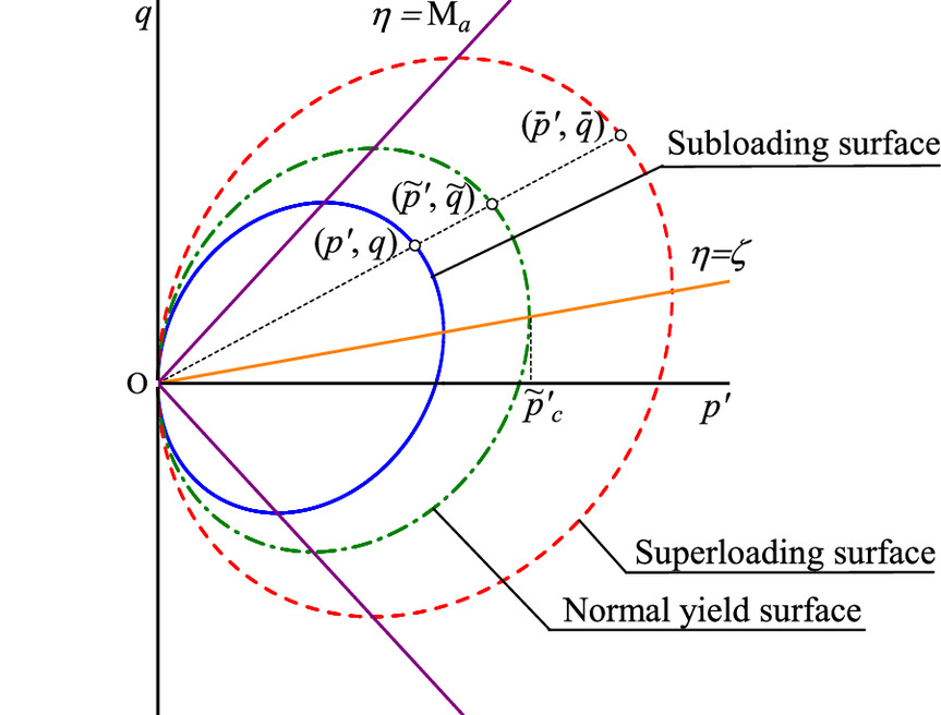
In addition, a subloading surface (Hashiguchi 1989; Asaoka et al. 1997) is introduced inside the superloading surface to incorporate the effect of overconsolidation into the model, as shown in Fig. 1. The similarity ratio of the subloading surface to the superloading surface is expressed in terms of R(0 < R ≤ 1). Its reciprocal, 1/R, represents the overconsolidation ratio. The current effective stress always exists on the subloading surface, not only at the time of loading but also at the time of unloading. The relationship holds between the effective stress on the superloading surface and that on the subloading surface that is conjugate to . By substituting this relationship into Eq. (26), the subloading surface can be expressed as follows:
(27)
Hardening Rule for the Normal Yield Surface
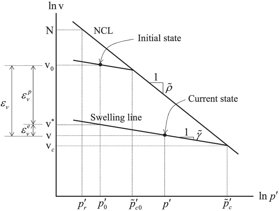
Following Hashiguchi (1995), suppose that the fully remolded and normally consolidated soil produces a straight line in the lnv − lnp′ plane during isotropic consolidation. Subsequently, the normal consolidation line (NCL) is given as follows:where = material constant that expresses the slope of the NCL and is called the compression index; = reference stress; and N = specific volume at .
(28)
Suppose that p′ at the intersection of the current elastic surface and the NCL determines , which is the magnitude of the normal yield surface. If the stress state and the specific volume at the intersection are given as , η = 0, and v = vc, the following two equations hold:
(29)
(30)
By equating the left-hand side of Eq. (29) with the left-hand side of Eq. (30), the following equation is obtained:
(31)
As this relationship should hold at the initial state t = 0, the following equation is obtained:where it should be noted that . represents the initial , which is referred to as the initial consolidation yield stress. The following equation is obtained by substituting Eqs. (31) and (32) into Eq. (14):
(32)
(33)
Eq. (33) can be transformed as
(34)
As the previous equation shows, Eq. (33) represents an isotropic hardening law of the normal yielding surface, where the isotropic hardening is governed by the plastic logarithmic volume strain. The hardening rule is illustrated in Fig. 2. Note here that for simplicity, the initial and current conditions are supposed to be in isotropic stress states.
Yield Function as a Subloading Surface
The equality of the yield function always holds owing to the application of the subloading surface.
Flow Rule
The associated flow rule is applied:where Λ( > 0) is the plastic multiplier in loading conditions, which can be determined by Prager’s (1949) consistency condition.
(39)
Evolution Rules for Internal State Variables
In this section, the evolution rules for the internal state variables have been briefly described. For detailed descriptions, refer to the original papers.
Evolution Rule of
Following Hashiguchi and Chen (1998) and Asaoka et al. (2002), the evolution rule for to describe the development of induced anisotropy is given aswhere = corotational rate tensor of ; and mb and br = material constants that define the evolution limit and the evolution rate, respectively. For the development of the formula, this study abbreviated Eq. (40) as follows:where = deviatoric part of .
(40)
(41)
Evolution Rule of
Following Asaoka (2003) and Noda and Asaoka (2007), the evolution rule for to describe the process by which a structured soil asymptotes to remolded state is given aswhere a, b, c = material constants that define the degradation rate of the structure; and cs = material constant that determines the contribution rate of the volumetric component to the shear component . Eq. (42) is also abbreviated as follows:
(42)
(43)
Evolution Rule of R
Following Hashiguchi (1989) and Asaoka et al. (2002), the evolution rule for R to describe the process by which an overconsolidated soil is transformed into normally consolidated state is given aswhere m represents the material constant that defines the degradation rate of overconsolidation. Eq. (44) is also abbreviated as follows:
(44)
(45)
Plastic Multiplier
Prager’s consistency condition, which is the condition for satisfying Eq. (37) during loading, is expressed as and in Eq. (47) can be transformed into corotational rate tensors (Asaoka et al. 2002) as
(47)
(48)
By substituting Eqs. (17), (9), (41), (43), and (45) and the material time derivative of Eq. (14) into Eq. (48), the plastic multiplier is obtained aswhere Ms and Ma = threshold values of hardening/softening and plastic compression/extension, respectively. Hardening occurs when , whereas softening occurs when . Moreover, plastic compression occurs when , and plastic expansion occurs when . See Asaoka et al. (2002) for a detailed discussion of these points.
(49)
(50)
(51)
Elastoplastic Constitutive Model
Loading Criterion
Following Asaoka et al. (1994), assuming that the denominator of the plastic multiplier shown in Eq. (49) is positive, the loading criterion is given as
(54)
The conditions keeping the denominator of the plastic multiplier positive are shown in the Appendix.
Equation of Internal State Variables
Asaoka et al. (2002; Asaoka 2003) showed that it is possible to derive the yield function of the Cam-Clay model from the state boundary surface (Roscoe et al. 1958; Atkinson and Bransby 1978), that is, the Roscoe surface, which is for normally consolidated soils, based on Henkel’s (1960) experiment. In this subsection, it is shown that the model that was derived in this study can explain Henkel’s experiment using a logic that follows the opposite path.
This study refers to it as the equation of internal state variables. Note that the initial values of the state variables must be determined in such a way that Eq. (56) is satisfied.
Suppose that the soil is in a less structured, normally consolidated, and isotropic state (, ). Consequently, Eq. (56) is transformed as
(57)
This equation implies that under the previous conditions, the specific volume is determined by the current stress state. This signifies that Eq. (57) represents a concrete form of the state boundary surface, and it shows that the previous model can explain Henkel’s experiment. In other words, the model was required to have the state boundary at an ultimate state.
Response of the Proposed Rate-Type Elastic Constitutive Equation
In this section, the mechanical properties of the rate-type elastic constitutive model given by Eq. (17) are revealed by comparing the model with the pressure-dependent rate-type (nonlinear) Hooke’s law (hereinafter referred to as Hooke’s law), which is used in the prototype of the SYS Cam-Clay model. The latter model can be expressed aswhere ν = Poisson’s ratio; = swelling index in the v − lnp′ plane; and .
(60)
(61)
Tables 1 and 2 show the material constants that were used. The initial void ratio e0 was set to 1.0. The material constants shown in Tables 1 and 2 are given such that their initial tangent moduli are equivalent to each other.
| Parameters | Value |
|---|---|
| Swelling index, | 0.004 |
| Poisson’s ratio, ν | 0.4 |
| Parameters | Value |
|---|---|
| Swelling index | 0.002 |
| Pseudo Poisson’s ratio | 0.4 |
Stress Cycles under Triaxial Condition
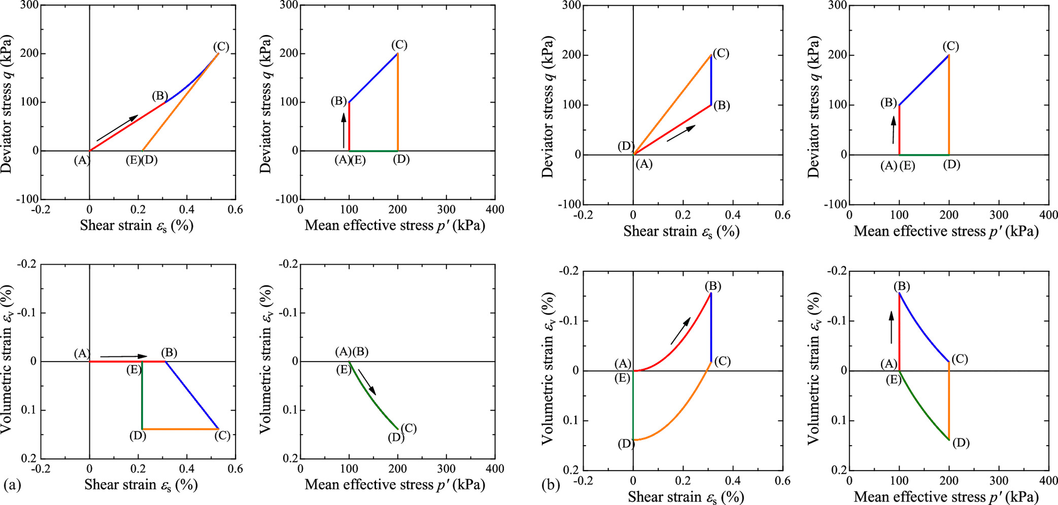
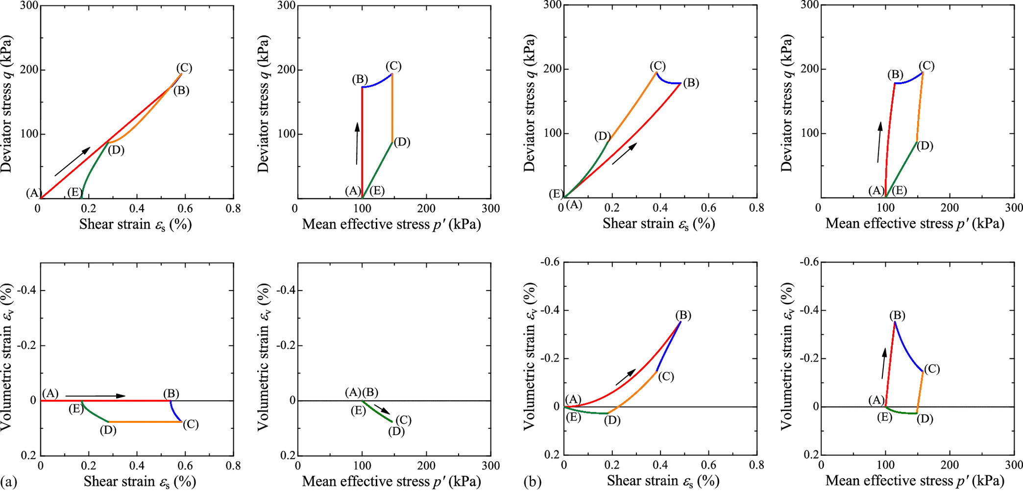
Fig. 3 shows the behavior of the proposed model when applying the following stress cycle under triaxial conditions.
<Cycle 1>
A.
B.
C.
D.
E.
In Hooke’s law, volume change does not depend on the change in the deviator stress q, whereas in the proposed model, q causes a volume change. In addition, no residual strain is observed during the stress cycle in the proposed model, whereas the shear strain remains approximately 0.2% during the cycle in Hooke’s law. It is worth noting that the proposed model has the same properties as the hyperelastic models proposed by Einav and Puzrin (2004) and Houlsby et al. (2005) under stress paths with nonrotation. Moreover, no shear strain occurs under constant-stress-ratio loading in the proposed model.
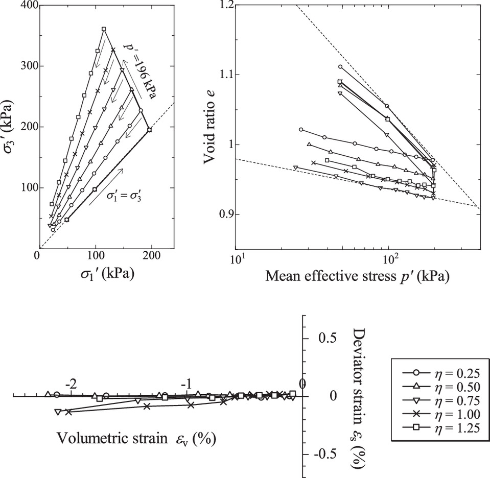
The results of the anisotropic swelling test of normally consolidated clay by Ohmaki (1979) are shown in Fig. 4 to indicate the validity of the proposed elastic constitutive equation. In this test, isotropic consolidation was first performed up to 196 kPa followed by drained shear with p′ = constant to various stress ratios. Subsequently, the swelling tests were conducted at a constant stress ratio. Stage loading was performed, and sufficient time was taken at each loading stage to drain the water. Fig. 4(a) shows the effective stress path, Fig. 4(b) shows the void ratio-mean effective stress relationship, and Fig. 4(c) shows the deviator strain–volume strain relationship. Fig. 4(b) indicates that the swelling characteristics are independent of the stress ratio. In Fig. 3, similar volume changes occur from (B) to (C) and from (D) to (E), and both elastic constitutive equations satisfy this point. Further, Fig. 4(c) shows that the deviator strain can be considered to be almost zero when p′ decreases at a constant stress ratio. The routes from (B) to (C) and from (D) to (E) in Fig. 3 are stress paths that change the mean effective stress at a constant stress ratio. The proposed elastic constitutive equation is reasonable because the rate-type Hooke’s law produces shear strain, while the proposed elastic constitutive equation does not produce it in these paths.
Stress Cycles under Plane Strain Conditions
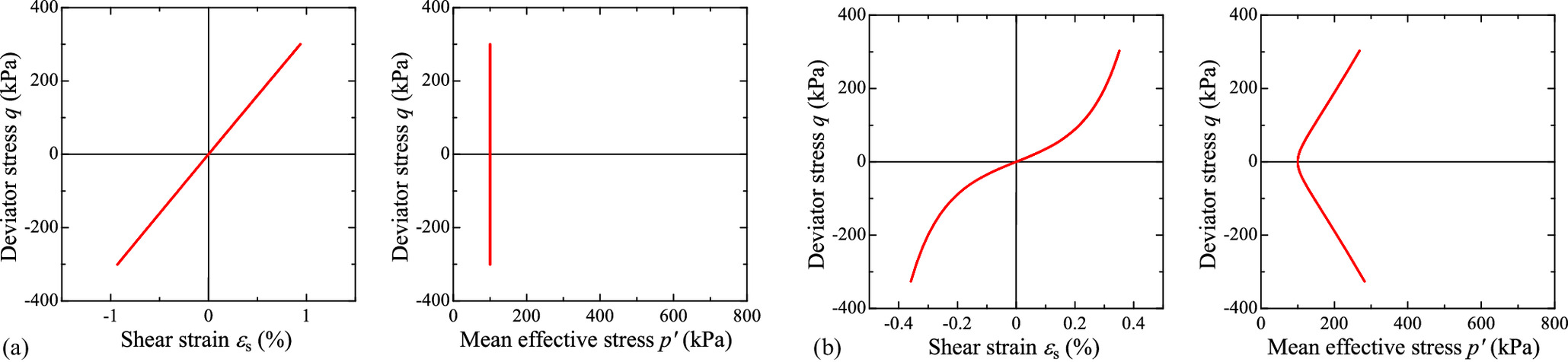
Fig. 5 shows the behavior of the models when applying the following stress cycle under plane strain conditions; this stress cycle is accompanied by rotation. Further, the stress path does not have to be identical between the two models since this stress cycle involves a plane strain condition.
<Cycle 2>
A.
B.
C.
D.
E.
In Hooke’s law, the shear strain remains after applying the stress cycle. In contrast, in the proposed model, although residual shear strain can remain for the stress cycles with rotation, it is too small to be seen in the graphs. There is no residual volume strain in either model. Each model satisfies the requirements for the elastic part of the Cam-Clay model.
The cyclic drainage shear behavior of Toyoura sand observed using a hollow torsional shear test apparatus to demonstrate the validity of the proposed elastic constitutive equation is shown in Fig. 6. In this test, a single swing cyclic shear was performed during the double swing cyclic shear by referring to Hinokio et al. (2001). During the double swing shear, volume compression occurs gradually with repeated positive and negative dilatancy, whereas the behavior is almost elastic during the single swing shear. Further, volume compression occurs gradually with repeated positive and negative dilatancy during the double swing shear, whereas the behavior is almost elastic during the single swing shear. An enlarged view of the behavior during the single swing shows that volume expansion occurs during loading, whereas volume contraction occurs during unloading. In Fig. 6(a), no volume change is observed in the processes from (A) to (B) and from (C) to (D), whereas in Fig. 6(b), the volume expands from (A) to (B) during loading and compresses from (C) to (D) during unloading. Therefore, the dilatancy exhibited by the proposed elastic constitutive equation reasonably captures the experimental trend.
Constant-Volume Cyclic Shear under Triaxial Conditions
Fig. 7 shows the behavior during a constant-volume cyclic shear under the triaxial condition. Hooke’s law does not produce a change in the mean effective stress because of the constant volume condition. Given that the mean effective stress is constant, the shear stiffness also remains constant in Hooke’s law. In contrast, in the proposed model, the mean effective stress increases with shearing, even in the constant-volume condition. In addition, shear stiffness increases as the shear progresses, owing to the increase in the mean effective stress. As discussed in the following, this feature aids the reproduction of cyclic mobility during liquefaction.
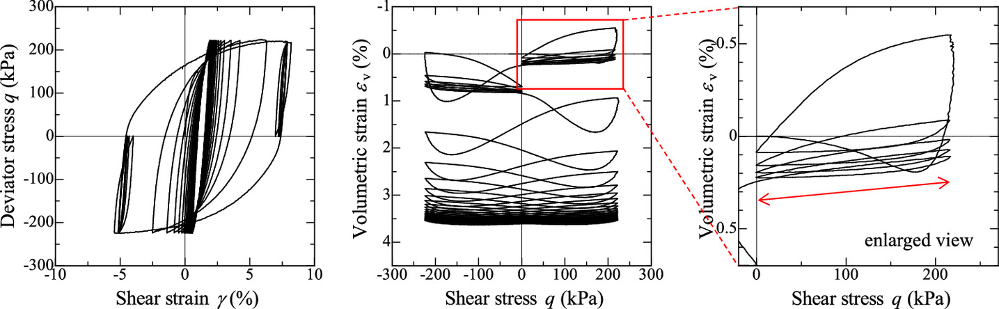
The behavior of Toyoura sand under cyclic undrained shear (Yamada et al. 2010) observed using a triaxial test apparatus to demonstrate the validity of the proposed elastic constitutive equation is shown in Fig. 8. The test results exhibit typical cyclic mobility. The deviator stress–shear strain relationship in Fig. 8(b) captures the trend of the stiffness recovery behavior in Fig. 7. In addition, the effective stress path in Fig. 8(b) captures the decreasing behavior of the mean effective stress observed during unloading in Fig. 7. As discussed in the following, these features are valuable for reproducing cyclic mobility during liquefaction.
Although the elastic strains produced in the previous examples are less than 1%, the application of finite deformation theory is important because plastic deformation occurs predominantly in elastic deformation, as shown in the following examples.
Behavior of the SYS Cam-Clay Model Employing the Proposed Elastic Constitutive Model
Differences between Sand and Clay in the SYS Cam-Clay Model
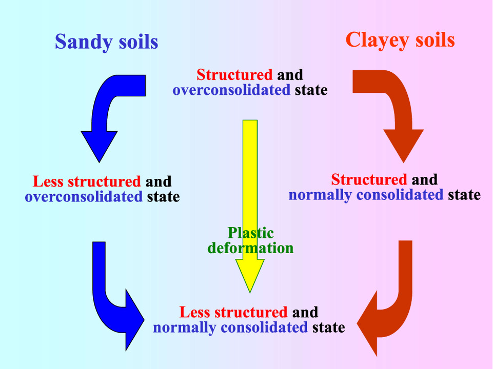
In the SYS Cam-Clay model, the difference in mechanical properties between sand and clay lies in the degradation rate of structure and overconsolidation, as shown in Fig. 9. The degradation rate of the structure is greater in the sand, and the degradation rate of overconsolidation is greater in clay (Asaoka et al. 2002). A combination of these degradation rates, that is, the ease of changing these quantities per unit of plastic deformation, makes it possible to reproduce the mechanical behavior of various soil types that are difficult to classify as either sand or clay. In this section, it will be demonstrated that the SYS Cam-Clay model can reproduce the element tests of typical clay and sand even after applying the rate-type elastic constitutive model defined in Eq. (17).
Monotonic Undrained-Shear Behavior of Clay
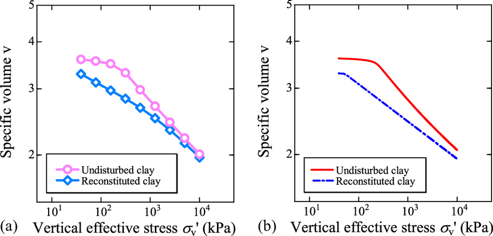
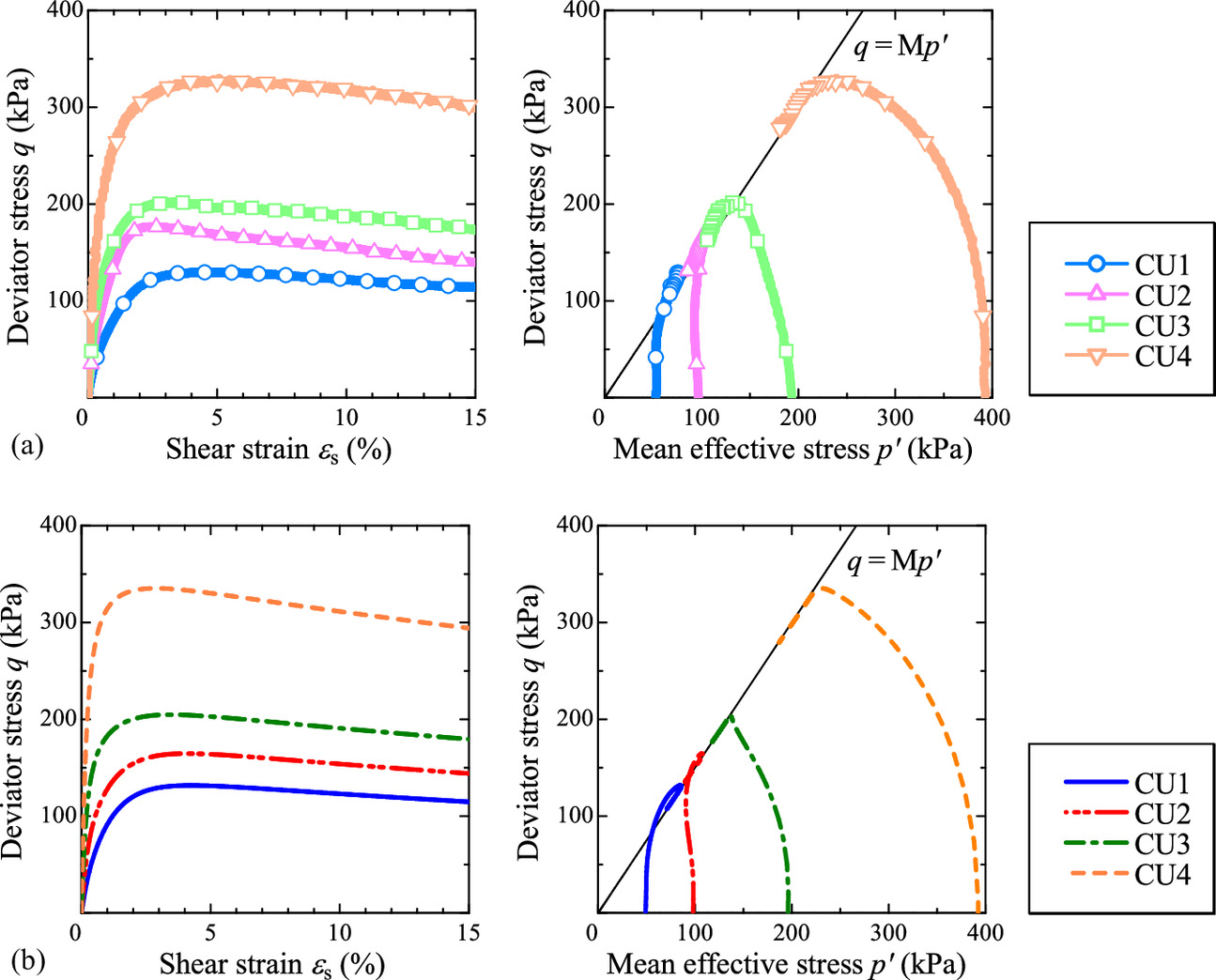
For capturing the typical behavior of clay under monotonic loading, this study considered the tests of Urayasu alluvial clay from Nakai et al. (2014). Figs. 10(a) and 11(a) show the oedometer tests and undrained-triaxial-shear tests on Urayasu clay, respectively. The simulation results of these experiments using the SYS Cam-Clay model are shown in Figs. 10(b) and 11(b). While the specimens are essentially undisturbed, Fig. 10 includes the oedometer test of the reconstituted sample and its simulation. The material constants and the initial values of the state variables used in the calculations are shown in Tables 3 and 4, respectively. A common single set of material constants was used in the calculations, and the initial values of the state variables were varied according to the initial stress. In oedometer tests, the behavior of naturally deposited clay approaches the one-dimensional compression behavior of the reconstituted sample from the bulky state owing to plastic deformation. The SYS Cam-Clay model captures this tendency. In the simulation of undrained-triaxial-shear tests, the SYS Cam-Clay model exhibits an unwinding behavior, which is peculiar to structured and overconsolidated clays, and a softening behavior with plastic compression below the CSL, which is peculiar to structured and normally consolidated clays.
| Parameters | Value |
|---|---|
| Elastoplastic | |
| Critical state constant, M | 1.5 |
| NCL intercept, N | 3.00 |
| Compression index, | 0.100 |
| Swelling index, | 0.020 |
| Pseudo Poisson’s ratio, | 0.1 |
| Evolution | |
| Ratio of to , cs | 0.4 |
| Degradation index of structure, a (b = c = 1.0) | 0.35 |
| Degradation index of overconsolidation, m | 1.0 |
| Rotational hardening index, br | 0.03 |
| Limitation of rotational hardening, mb | 1.0 |
| Test type | Test name | Condition | Initial values | |||||
|---|---|---|---|---|---|---|---|---|
| Specific volume, v0 | Mean effective stress, (kPa) | Stress ratio, η0 | Degree of structure, | Degree of overconsolidation, 1/R0 | Degree of anisotropy, ζ0 | |||
| Oedometer tests | OT1 | Undisturbed | 3.6 | 39.2 | 0 | 12.7 | 4 | 0.231 |
| OT2 | Remolded | 3.29 | 39.2 | 0 | 1 | 1 | 0.107 | |
| Undrained triaxial tests | CU1 | Undisturbed | 3.55 | 49.1 | 0 | 11.9 | 3.4 | 0.205 |
| CU2 | Undisturbed | 3.4 | 98.1 | 0 | 10.2 | 2.1 | 0.167 | |
| CU3 | Undisturbed | 3.25 | 196.2 | 0 | 7.8 | 1.2 | 0.107 | |
| CU4 | Undisturbed | 3.01 | 392.4 | 0 | 6 | 1.01 | 0.052 | |
Monotonic Undrained-Shear Behavior of Sand
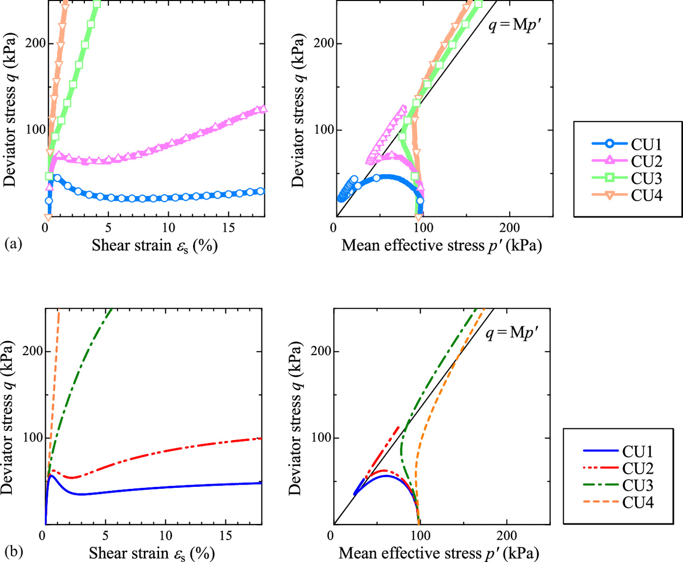
For capturing the typical behavior of sand under monotonic loading, this study considered the triaxial shear tests of Soma siliceous sand from Nakai et al. (2014). Fig. 12 shows the undrained triaxial shear tests on Soma sand at different densities and their simulations. The material constants and initial values used in the calculations are shown in Tables 5 and 6, respectively. As in the case of clay, a common single set of material constants was used in the calculations, and the initial values of the state variables were varied according to the density. The simulations capture the typical shear behavior of sand, which includes the shifting behavior from softening to hardening observed during the shearing of medium-density sand.
| Parameters | Value |
|---|---|
| Elastoplastic | |
| Critical state constant, M | 1.5 |
| NCL intercept, N | 3.00 |
| Compression index, | 0.100 |
| Swelling index, | 0.020 |
| Pseudo Poisson’s ratio, | 0.1 |
| Evolution | |
| Ratio of to , cs | 0.4 |
| Degradation index of structure, a (b = c = 1.0) | 0.35 |
| Degradation index of overconsolidation, m | 1.0 |
| Rotational hardening index, br | 0.03 |
| Limitation of rotational hardening, mb | 1.0 |
| Test name | Condition | Initial values | |||||
|---|---|---|---|---|---|---|---|
| Specific volume, v0 | Mean effective stress, (kPa) | Stress ratio, η0 | Degree of structure, | Degree of overconsolidation, 1/R0 | Degree of anisotropy, ζ0 | ||
| CU1 | Loose | 2.02 | 98.1 | 0 | 4.5 | 2 | 0 |
| CU2 | Medium loose | 1.95 | 98.1 | 0 | 4 | 4 | 0 |
| CU3 | Medium dense | 1.84 | 98.1 | 0 | 1.7 | 7 | 0 |
| CU4 | Dense | 1.74 | 98.1 | 0 | 1 | 15 | 0 |
As shown in these examples, the introduction of the proposed elastic constitutive model does not impair the basic performance of the SYS Cam-Clay model.
Cyclic-Undrained-Shear Behavior of Sand
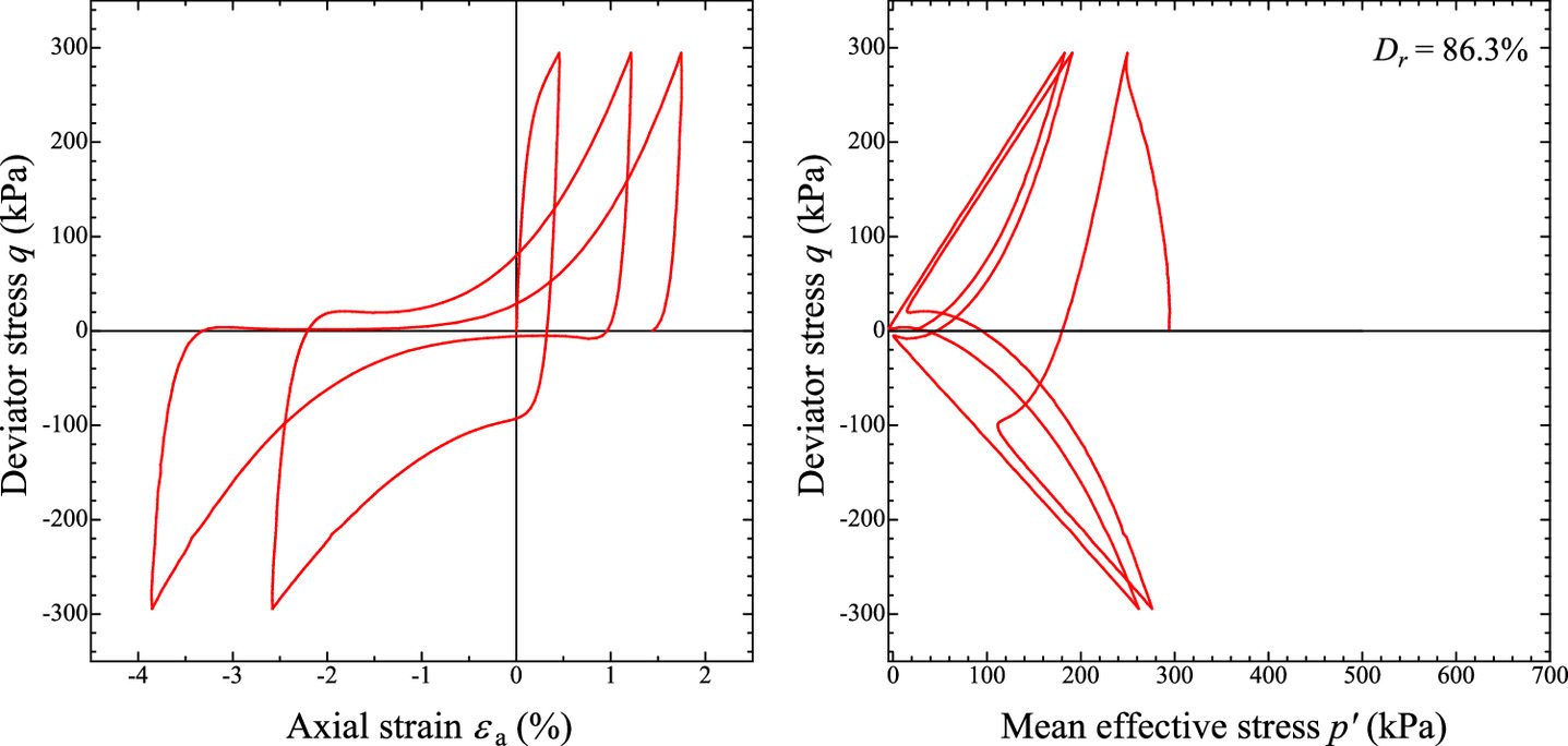
The cyclic-undrained-shear behavior of the SYS Cam-Clay model integrated with the proposed elastic constitutive model is shown in Fig. 13. The same material constants as shown in Table 5 and the same initial values as CU3 in Table 6 were used. This study compared the behavior of the prototype of the SYS Cam-Clay model with that of the model proposed in this paper to clarify the effect of the proposed elastic model. In the case of Hooke’s law, the compression and swelling indices were set to and , respectively, and the other material constants and initial values were the same as when applying the proposed elastic constitutive model.
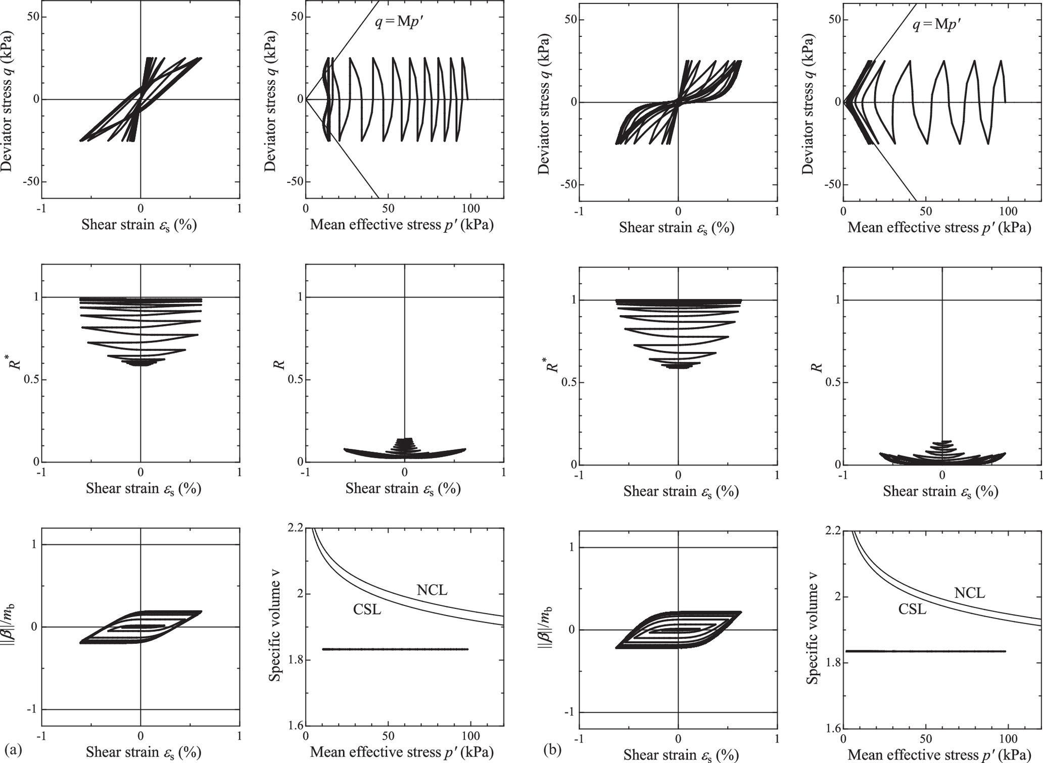
Both models can describe the decrease in the mean effective stress caused by plastic compression. This behavior is caused by the structural degradation and accumulation of overconsolidation. In contrast, there is a clear difference in the behavior after the mean effective stress reduction. In the case of the prototype model, the effective stress remains constant at the time of unloading, whereas in the case of the proposed model, the effective stress path is toward the origin. There is also a significant difference in the shape of the hysteresis loop drawn in the deviator stress–shear strain relationship. The SYS Cam-Clay model integrated with the proposed elastic constitutive model shows a tendency to recover stiffness when applying the deviator stress, which is often seen in liquefaction. As recognized in Fig. 7, these features are obtained from the properties of the proposed elastic constitutive model. Thus, the proposed elastic constitutive model can play a useful role in describing cyclic mobility.
However, it is necessary to improve the effective-stress reduction process before liquefaction and the sustained evolution of strain amplitude after liquefaction to reproduce cyclic mobility more quantitatively. Such issues will be addressed in the future. As mentioned in the “Introduction” section, we aim to fully reproduce cyclic mobility by introducing the elastic constitutive equation proposed in this paper and rotational hardening into the combined-loading elastoplastic constitutive model proposed by the authors (Yamada et al. 2022a).
Conclusions
This paper proposed a new rate-type elastic constitutive equation that can be applied to finite deformation elastoplastic constitutive models that supposes the additive decomposition of stretching and an objective stress rate based on the hyperelastic constitutive equation considering the confining pressure dependence in infinitesimal deformation theory by Einav and Puzrin (2004) or Houlsby et al. (2005). Although the proposed elastic constitutive equation is a hypoelastic constitutive equation, the elastic volume change is independent of the stress path, and the residual strain generated at a certain effective stress cycle is considerably smaller than that of the nonlinear rate-type Hooke’s law (the residual strain is completely zero when no rotation occurs). In addition, the proposed elastic constitutive equation considers the pressure dependency and can express elastic dilatancy.
The proposed rate-type elasticity constitutive equation was applied to improve the SYS Cam-Clay model. The basic behavior for clay and sand was illustrated to demonstrate that the elastoplastic constitutive equation can express the decrease in mean effective stress under undrained shear conditions and the stiffness recovery behavior with increasing shear stress, which are important for describing cyclic mobility without sacrificing the original high expressive capability of the equation.
Appendix. Conditions for Keeping the Denominator of Plastic Multiplier Positive
The denominator of the plastic multiplier given in Eq. (49) can be expressed as
(62)
Therefore, the conditions for keeping the denominator of the plastic multiplier positive can be given as
(63)
(64)
Data Availability Statement
All data, models, and codes generated or used during the study appear in the published article.
Acknowledgments
This study was supported by JSPS Grants-in-Aid for Scientific Research (Grant Nos. 19H02402 and 17H01289).
References
Asaoka, A. 2003. “Consolidation of clay and compaction of sand—An elasto-plastic description-, Keynote lecture.” In Vol. 2 of Proc., 12th Asian Regional Conf., on Soil Mechanics and Geotechnical Engineering, 1157–1195. Singapore: World Scientific.
Asaoka, A., M. Nakano, and T. Noda. 1994. “Soil–water coupled behaviour of saturated clay near/at critical state.” Soils Found. 34 (1): 91–105. https://doi.org/10.3208/sandf1972.34.91.
Asaoka, A., M. Nakano, and T. Noda. 1997. “Soil–water coupled behavior of heavily overconsolidated clay near/at critical state.” Soils Found. 37 (1): 13–28. https://doi.org/10.3208/sandf.37.13.
Asaoka, A., M. Nakano, and T. Noda. 1998. “Superloading yield surface concept for the saturated structured soils.” In Proc., 4th European Conf., on Numerical Methods in Geotechnical Engineering, 233–242. London: European Regional Technical Committee.
Asaoka, A., M. Nakano, and T. Noda. 2000. “Superloading yield surface concept for highly structured soil behavior.” Soils Found. 40 (2): 99–110. https://doi.org/10.3208/sandf.40.2_99.
Asaoka, A., T. Noda, E. Yamada, K. Kaneda, and M. Nakano. 2002. “An elasto-plastic description of two distinct volume change mechanisms of soils.” Soils Found. 42 (5): 47–57. https://doi.org/10.3208/sandf.42.5_47.
Atkinson, J. H., and P. L. Bransby. 1978. The mechanics of soils; an introduction to critical state soil mechanics. New York: McGraw-Hill.
Dienes, J. K. 1979. “On the analysis of rotation and stress rate in deforming bodies.” Acta Mech. 32: 217–232. https://doi.org/10.1007/BF01379008.
Einav, I., and A. M. Puzrin. 2004. “Pressure-dependent elasticity and energy conservation in elasto-plastic models for soils.” J. Geotech. Geoenviron. Eng. 130 (1): 81–92. https://doi.org/10.1061/(ASCE)1090-0241(2004)130:1(81).
El-Shoby, M. A. 1969. “Elastic behavior of sand.” J. Soil Mech. Found. Div. 95: 1393–1409. https://doi.org/10.1061/JSFEAQ.0001349.
Golchin, A., and A. Lashkari. 2014. “A critical state sand model with elastic–plastic coupling.” Int. J. Solids Struct. 51 (15–16): 2807–2825. https://doi.org/10.1016/j.ijsolstr.2014.03.032.
Green, A. E., and P. M. Naghdi. 1965. “A general theory of an elastic-plastic continuum.” Arch. Ration. Mech. Anal. 18 (4): 251–281. https://doi.org/10.1007/BF00251666.
Hashiguchi, K. 1978. “Plastic constitutive equations of granular materials.” In Proc. US–Japan Seminar Continuum Mech. and Statistical Approaches in the Mech. of Granular Materials, 321–329. Tokyo: Gakujutsu Bunken Fukyu-Kai.
Hashiguchi, K. 1989. “Subloading surface model in unconventional plasticity.” Int. J. Solids Struct. 25 (8): 917–945. https://doi.org/10.1016/0020-7683(89)90038-3.
Hashiguchi, K. 1995. “On the linear relations of V-lnp and lnv-lnp for isotropic consolidation of soils.” Int. J. Numer. Anal. Methods Geomech. 19: 367–376. https://doi.org/10.1002/nag.1610190505.
Hashiguchi, K., and Z.-P. Chen. 1998. “Elastoplastic constitutive equation of soils with the subloading surface and the rotational hardening.” Int. J. Numer. Anal. Methods Geomech. 22: 197–227. https://doi.org/10.1002/(SICI)1096-9853(199803)22:3%3C197::AID-NAG914%3E3.0.CO;2-T.
Hashiguchi, K., and T. Mase. 2010. “Physical interpretation and quantitative description of cyclic mobility by the subloading surface model.” [In Japanese.] Jpn. Geotech. J. 6 (2): 225–241.
Hashiguchi, K., T. Mase, and Y. Yamakawa. 2022. “Elaborated subloading surface model for accurate description of cyclic mobility in granular materials.” Acta Geotech. 17 (3): 699–719. https://doi.org/10.1007/s11440-021-01203-y.
Henkel, D. J. 1960. “The shear strength of saturated remolded clay.” In Proc., Research Conf., on Shear Strength of Cohesive Soils, 533–540. Reston, VA: ASCE.
Hinokio, M., T. Nakai, T. Hoshikawa, and H. Yoshida. 2001. “Dilatancy characteristics and anisotropy of sand under monotonic and cyclic loading.” Soils Found. 41 (3): 107–124. https://doi.org/10.3208/sandf.41.3_125.
Houlsby, G. T., A. Amorosi, and E. Rojas. 2005. “Elastic moduli of soils dependent on pressure: A hyperelastic formulation.” Géotechnique 55 (5): 383–392. https://doi.org/10.1680/geot.2005.55.5.383.
Jaumann, G. 1911. “Geschlossenes system physikalischer und chemischer differentialgesetze.” Sitzber, Akad, Wiss, Wien (IIa) 120: 385–530.
Mikasa, M. 1959. “Classification table of engineering property of soils ant its application.” [In Japanese.] In Proc., Annual Conf. Japan Civil Engineering Society 67–74. Japan: Japan Civil Engineering Society.
Muir Wood, D. 1990. Soil behavior and critical state soil mechanics. Cambridge, UK: Cambridge University Press.
Nakai, K., T. Noda, M. Nakano, T. Murakami, and A. Asaoka. 2014. “Understanding of the statal organization, physical properties, mechanical characteristics of the ground in Urayasu city.” [In Japanese.] In Proc., Special Symp. on the Great East Japan Earthquake, 114–122.
Nguyen, H.-S., M. Tashiro, M. Inagaki, S. Yamada, and T. Noda. 2015. “Simulation and evaluation of improvement effects by vertical drains/vacuum consolidation on peat ground under embankment loading based on a macro-element method with water absorption and discharge functions.” Soils Found. 55 (5): 1044–1057. https://doi.org/10.1016/j.sandf.2015.09.007.
Noda, T., and A. Asaoka. 2007. “Nakai, K. and Tashiro, M: Structural re-upgradation in clay and sand accompanying plastic swelling.” In Proc., 13th Asian Regional Conf., On Soil Mechanics and Geotechnical Engineering, 23–26. London: ISSMGE.
Noda, T., A. Asaoka, M. Nakano, E. Yamada, and M. Tashiro. 2005a. “Progressive consolidation settlement of naturally deposited clayey soil under embankment loading.” Soils Found. 45 (5): 39–51. https://doi.org/10.3208/sandf.45.5_39.
Noda, T., A. Asaoka, and S. Yamada. 2007. “Some bearing capacity characteristics of a structured naturally deposited clay soil.” Soils Found. 47 (2): 285–301. https://doi.org/10.3208/sandf.47.285.
Noda, T., Y. Shotaro, and A. Asaoka. 2005b. “Elasto-plastic behavior of naturally deposited clay during/after sampling.” Soils Found. 45 (1): 54–64.
Noda, T., S. Yamada, T. Nonaka, and M. Tashiro. 2015. “Study on the pore water pressure dissipation method as a liquefaction countermeasure using soil–water coupled finite deformation analysis equipped with a macro-element method.” Soils Found. 55 (5): 1129–1138. https://doi.org/10.1016/j.sandf.2015.09.013.
Nonaka, T., S. Yamada, and T. Noda. 2017a. “Verification of a macro-element method in the numerical simulation of the pore water pressure dissipation method—A case study on a liquefaction countermeasure with vertical drains under an embankment.” Soils Found. 57 (3): 472–487. https://doi.org/10.1016/j.sandf.2017.05.012.
Nonaka, T., S. Yamada, and T. Noda. 2017b. “Soil–water coupled analysis of pore water pressure dissipation method targeting even the case where excess pore water pressure exceeds the permissible value specified in the current design—examinations of effectiveness in reclaimed ground.” Geotech. Eng. J. SEAGS AGSSEA 48 (3): 19–31.
Ohmaki, M. 1979. “Study on deformation characteristics of saturated clay.” [In Japanese.] Ph.D. thesis, Dept. of Civil Engineering, Kyoto Univ.
Prager, W. 1949. “Recent developments in the mathematical theory of plasticity.” J. Appl. Phys. 20 (3): 235–241. https://doi.org/10.1063/1.1698348.
Roscoe, K. H., and J. B. Burland. 1968. “On the generalized stress–strain behavior of wet clay.” In Engineering plasticity, 535–609. Cambridge, UK: Cambridge University Press.
Roscoe, K. H., A. N. Schofield, and A. Thurairajah. 1963. “Yielding of clays in states wetter than critical.” Géotechnique 13 (3): 211–240. https://doi.org/10.1680/geot.1963.13.3.211.
Roscoe, K. H., A. N. Schofield, and C. P. Wroth. 1958. “On the yielding of soils.” Géotechnique 8 (1): 22–53. https://doi.org/10.1680/geot.1958.8.1.22.
Schofield, A. N., and C. P. Wroth. 1968. Critical state soil mechanics. New York: McGraw-Hill.
Sekiguchi, H., and H. Ohta. 1977. “Induced anisotropy and time dependency in clays.” In Vol. 9 of Proc., Int. Conf., on Soil Mechanics and Foundation Engineering, Specialty Session, 229–238. Bangkok, Thailand: Asian Institute of Technology.
Tafili, M., and T. Triantafyllidis. 2019. “State-dependent dilatancy of soils: Experimental evidence and constitutive modeling.” In Recent developments of soil mechanics and geotechnics in theory and practice, edited by T. Triantafyllidis, 54–84. Cham, Switzerland: Springer.
Takaine, T., M. Tashiro, T. Shiina, T. Noda, and A. Asaoka. 2010. “Predictive simulation of deformation and failure of peat-calcareous soil layered ground due to multistage test embankment loading.” Soils Found. 50 (2): 245–260. https://doi.org/10.3208/sandf.50.245.
Tashiro, M., S. H. Nguyen, M. Inagaki, S. Yamada, and T. Noda. 2015. “Simulation of large-scale deformation of ultra-soft peaty ground under test embankment loading and investigation of effective countermeasures against residual settlement and failure.” Soils Found. 55 (2): 343–358. https://doi.org/10.1016/j.sandf.2015.02.010.
Tashiro, M., T. Noda, M. Inagaki, M. Nakano, and A. Asaoka. 2011. “Prediction of settlement in natural deposited clay ground with risk of large residual settlement due to embankment loading.” Soils Found. 51 (1): 133–149. https://doi.org/10.3208/sandf.51.133.
Tighe, B. P. 2014. “Shear dilatancy in marginal solids.” Granular Matter 16 (2): 203–208. https://doi.org/10.1007/s10035-013-0436-6.
Truesdell, C. 1965. “Hypo-elasticity.” J. Rational Mech. Anal. 4: 83–133.
Yamada, S., T. Noda, M. Nakano, and A. Asaoka. 2022a. “Combined-loading elastoplastic constitutive model for a unified description of the mechanical behavior of the soil skeleton.” Comput. Geotech. 141: 104521. https://doi.org/10.1016/j.compgeo.2021.104521.
Yamada, S., T. Noda, M. Tashiro, and H.-S. Nguyen. 2015. “Macro-element method with water absorption and discharge functions for vertical drains.” Soils Found. 55 (5): 1113–1128. https://doi.org/10.1016/j.sandf.2015.09.012.
Yamada, S., T. Sakai, M. Nakano, and T. Noda. 2022b. “Method to introduce the cementation effect into existing elastoplastic constitutive models for soils.” J. Geotech. Geoenviron. Eng. 148 (5): 04022013. https://doi.org/10.1061/(ASCE)GT.1943-5606.0002727.
Yamada, S., T. Takamori, and K. Sato. 2010. “Effects on reliquefaction resistance produced by changes in anisotropy during liquefaction.” Soils Found. 50 (1): 9–25. https://doi.org/10.3208/sandf.50.9.
Zhang, F., B. Ye, T. Noda, M. Nakano, and K. Nakai. 2007. “Explanation of cyclic mobility of soils: Approach by stress-induced anisotropy.” Soils Found. 47 (4): 635–648. https://doi.org/10.3208/sandf.47.635.
Information & Authors
Information
Published In

International Journal of Geomechanics
Volume 23 • Issue 2 • February 2023
Copyright
This work is made available under the terms of the Creative Commons Attribution 4.0 International license, https://creativecommons.org/licenses/by/4.0/.
History
Received: Jul 13, 2021
Accepted: Sep 21, 2022
Published online: Nov 22, 2022
Published in print: Feb 1, 2023
Discussion open until: Apr 22, 2023
ASCE Technical Topics:
- Clays
- Constitutive relations
- Continuum mechanics
- Deformation (mechanics)
- Effective stress
- Elastic analysis
- Elastoplasticity
- Engineering fundamentals
- Engineering mechanics
- Geomechanics
- Geotechnical engineering
- Mathematics
- Shear stress
- Soil dilatancy
- Soil mechanics
- Soil properties
- Soil stress
- Soils (by type)
- Solid mechanics
- Stress (by type)
- Structural analysis
- Structural engineering
- Structural mechanics
Authors
Metrics & Citations
Metrics
Citations
Download citation
If you have the appropriate software installed, you can download article citation data to the citation manager of your choice. Simply select your manager software from the list below and click Download.