Effects of Joint and Crack Geometry on Hydraulic Jacking in Lined and Unlined Spillways
Publication: Journal of Hydraulic Engineering
Volume 150, Issue 5
Abstract
Offsets into the flow at joints or cracks can cause hydraulic jacking of spillway chute linings or remove rock blocks from unlined chutes. Previous articles established experimentally validated relations for uplift pressure and flow into square-edged joints and cracks oriented perpendicularly to the flow and chute surface. This paper addresses chamfered and rounded edges, tilts into or away from the flow, skewed orientations, irregular midslab cracks, and bevels or relief slots used to remediate existing offsets. Chamfers and rounding reduce uplift by diminishing the effective offset height. Tilts and bevels away from the flow reduce uplift and joint flow in proportion to where = tilt angle, whereas tilts toward the flow cause marginal increases. Very flat beveling is needed for major uplift reduction; as a result, relief slots that shift the offset downstream from the joint may be more effective remediation alternatives. For skewed joints, uplift is reduced in proportion to where is the deviation from perpendicular orientation. Flow through various irregular joints was reduced compared with that through regular square-edged joints.
Practical Applications
Existing offsets into the flow at joints or cracks in spillway chutes create the potential for hydraulic jacking failures that can destroy a spillway chute and potentially lead to uncontrolled release of reservoir storage. This study used laboratory experiments to evaluate several treatments that can reduce the risk of hydraulic jacking failure, including chamfering, rounding, and beveling of offsets or milling slots to shift the offset further downstream from an open joint. If the goal is to reduce uplift to 30% or less of that caused by the untreated offset, very flat beveling is needed and relief slots are more effective than bevels that involve the same volume of material removal. The study also shows that skewed joints (i.e., twisted so that their axis is not perpendicular to the flow direction) can reduce uplift pressures by about 55%, although this may not be an economic or practical construction approach for most spillways. Data collected in the study also aid in the estimation of uplift pressures at rounded and chamfered joints and midslab cracks, and at natural joints in unlined rock chutes.
Introduction
The Oroville Dam spillway failure in 2017 highlighted the importance of hydraulic jacking as a potential failure mode of concrete spillway chutes (IFT 2018). Stagnation of flow at joints or cracks where offsets project up into the flow injects high-pressure water into the foundation of spillway chute slabs, which can cause erosion and potentially lift (jack) slabs further up into the flow. Wahl and Heiner (2024a, b) provided relations that can be used to predict uplift pressures and flow rates associated with square-edged joints or linear cracks oriented normal to the flow direction and chute surface. Offsets into the flow also have the potential in high-velocity conditions to trigger damaging cavitation. This research focused only on the generation of stagnation pressure that may lift slabs, jack rocks out of place, or drive flow into a joint. These effects with associated severe consequences are possible at flow velocities much lower than those needed to cause cavitation.
In field cases, many other joint orientations and configurations are possible, including skewness (rotation of the joint axis in the plane of the chute), tilt (rotation of the joint in the vertical plane that parallels the flow direction), and chamfered or rounded edges. In addition, natural cracks in the middle of slabs may be nonlinear, with skewed orientations that vary along the length of the crack. Since the Oroville spillway failure, there has been strong interest in rehabilitating joints that may be in poor condition (e.g., Smith et al. 2023; Gilbert et al. 2023). To remediate spillways with existing offset joints or cracks, offsets may be beveled down by grinding; another alternative remediation option is milling the downstream slab to effectively shift the offset downstream from the joint opening. This paper presents experimental data on the changes in uplift pressure and joint flow caused by these variations from idealized square-edged geometries.
Unlined spillway chutes that are cut through rock are prone to hydraulic jacking of individual rock blocks (e.g., Bollaert 2010; George 2015; Pells 2016; Koulibaly et al. 2021), which can lead to headcutting and an uncontrolled release of stored water. Concern for such a possibility prompted evacuation of downstream populations when headcut erosion occurred in the Oroville auxiliary spillway channel during its operation following the hydraulic jacking failure of the service spillway. Recent research has explored means for identifying other auxiliary spillways that could be at risk of similar erosion (Ghimire and Schulenberg 2021). The tests of skewed and tilted joints in the present paper provide insight into the hydraulic forces that are applied to rock blocks, which may facilitate various analytical methods for modeling their removal, which is a complex phenomenon involving rock strength, joint mechanics, and the forces exerted by the flow.
Literature Review
Wahl and Heiner (2024b) provided experiment-based equations for estimating the stagnation pressure generated at square-edged offsets into a spillway flow, which serves as the driving pressure head for flow through a joint or crack. Uplift pressure measured in sealed (nonvented) joints is shown to vary as a function of the velocity head of the boundary layer flow intercepted by the joint (), the gap width to offset height ratio (), and the ratio of flow depth to offset height (), where is the flow depth, is the gap width, and is the offset height (Fig. 1).
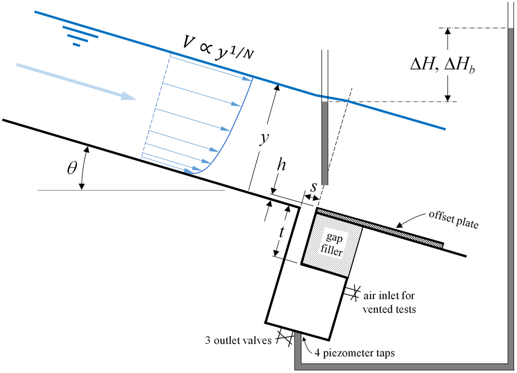
For uniform or gradually varied flows of known depth and velocity, the velocity profile approaching an offset can be described by a power-curve equation , where can be estimated as (Wahl and Heiner 2024b)where is the Darcy–Weisbach friction factor; and is the von Kármán constant, which is assumed to have a value of 0.4. Eq. (1) is an adjustment of the relations (Chen 1991) and (Nunner 1956). With known, the velocity head of the boundary layer flow striking the offset can be computed fromwhere = acceleration due to gravity; and , where . The parameter is the familiar energy coefficient used to compute the mean channel velocity head .
(1)
(2)
The uplift pressure head generated at an offset into the flow is given by a series of equationswhere is the base of natural logarithms. Uplift pressure head can be expressed in relation to the mean flow velocity head using .
(3)
(4a)
(4b)
(5)
The flow through a joint can be computed by applying an orifice equation to the joint (Wahl and Heiner 2024a), taking from Eq. (5) as the upstream head and assuming either atmospheric pressure below the joint or a backpressure head, , related to the drainage characteristics of the sitewhere = discharge per unit width through the joint; is a discharge coefficient; = width of the gap (Fig. 1); and = acceleration due to gravity. Both and are referenced to the piezometric head associated with the chute flow over the joint, and thus represent net head above the prevailing flow depth. The discharge coefficient for square-edged joints oriented normal to the flow direction and chute surface was shown to bewhere and = average velocities through the joint and in the chute, respectively. When determining an unknown flow rate, Eqs. (6) and (7) must be solved iteratively because the velocity through the gap depends on the discharge coefficient.
(6)
(7)
Two previous experimental studies of hydraulic jacking were conducted at the Bureau of Reclamation hydraulics laboratory in Denver, Colorado (Johnson 1976; Frizell 2007). The Johnson (1976) experiments were performed in a small open-channel facility with velocities as high as and measured uplift pressures only in a sealed joint (i.e., there was no net flow through the joint). Johnson suggested future testing of joints with various tilted and skewed orientations. Frizell (2007) used a water tunnel facility with an adjustable joint tested at flow velocities as high as , and this test program included joints with square-edged, rounded, and chamfered edges. Frizell (2007) observed that chamfered and rounded edges caused joints to perform as though they were effectively wider than their actual dimension, and provided test data and curves for rounded and chamfered edges of specific sizes but did not give general methods to account for effects of the different edge types. Sánchez (2022) performed computational fluid dynamics simulations of the Frizell (2007) experiments that confirmed Frizell’s general observations and also indicated that the chute slope has no special influence on the uplift pressure head generated at the offset. Both Johnson (1976) and Frizell (2007) discussed the potential importance of the boundary layer on uplift pressures and Frizell used laser-based particle image velocimetry (PIV) to map the complex velocity fields in the vicinity of one joint configuration. The relations given by Wahl and Heiner (2024b) incorporate the boundary layer via the exponent .
Development of internal pressures in rock joints has been the subject of several experimental studies and modeling efforts. Bollaert and Schleiss (2005) measured the dynamic pressures in simulated joints of rock-lined plunge pools with water jets (aerated and nonaerated) directed roughly normal to the rock surface. Forces applied to rock blocks and joints at the surface of unlined chutes, in which flow generally is parallel to the surface, have been studied using flume-based experiments (George 2015; Pells 2016; Koulibaly et al. 2023), and computational models for spillway scour simulation have been proposed and demonstrated (Bollaert 2010; Gardner 2023; Hurst et al. 2023). Field studies of forces applied to instrumented rock blocks also were performed by George (2015).
Experimental Facility—General
An experimental facility was constructed in early 2021 in the Bureau of Reclamation’s hydraulics laboratory in Denver, Colorado to measure uplift pressures within sealed offset joints and flow rates at partially vented joints. Wahl and Heiner (2024b) provided a detailed description of the facility; the overview here focuses on aspects relevant to the tests of irregular joints.
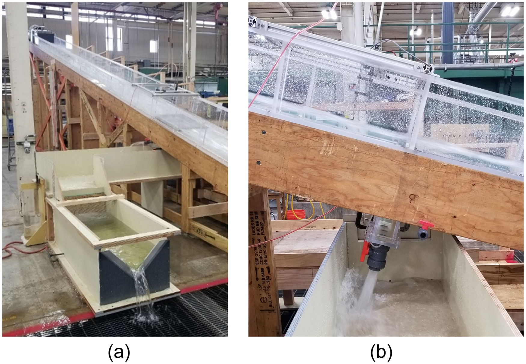
The 0.61-m-wide (2 ft) smooth acrylic flume on a fixed 15° slope is equipped with an adjustable spillway joint located near the downstream end (Fig. 2). The approach distance to the joint is , producing well-developed uniform or gradually varied flow profiles, depending on discharge. Flow enters through a jet box that can be used to adjust the incoming Froude number. The flume is supplied from the laboratory’s fixed pumps and venturi meter flow measurement systems which include meters from 76- to 356-mm (3- to 14-in.) diameter calibrated against a weight-based tank. Uncertainty of discharge measurements from this system generally is or less.
The model spillway joint consists of a (.) chamber in the flume floor that spans most of the channel width. The chamber extends 44 cm (17.25 in.) below the flume floor and is equipped with three 50-mm-diameter (2-in.) outlet valves at the bottom and a 19-mm-diameter (¾-in.) air inlet valve near the top of the chamber. Plates installed on the flume floor downstream from the joint create offsets into the flow, , to simulate a displaced spillway slab, and a portion of the chamber can be filled with solid materials to vary the width of the gap, , and the thickness of the joint, . Tested offsets were constructed from a variety of materials, including brass, aluminum, high-density foam, expanded PVC panels, and marine plywood. Care was taken to ensure that materials were water resistant and suitably rigid to avoid deformation during tests in which large uplift forces were generated. Gap widths and offset heights were measured for each configuration using digital calipers or feeler gauges and a machinist’s height gauge. Control of the gap width was less precise in the middle of the joints than at the chute surface where gap widths were measured. The floor of the flume was constructed from 19-mm-thick (.) acrylic, and there was a slight overhang of this floor piece over the upstream wall of the chamber below the flume [about 1.1 mm (0.043 in.)]. This caused the effective gap width to be slightly greater below the flume floor; this issue is more significant for very narrow gap widths.
Sealed joint testing to determine maximum uplift pressure head was performed with all valves on the chamber closed. For vented testing to evaluate flow rates through joints, valves were opened incrementally and joint discharge from the chamber was measured with a 90° V-notch weir installed in a 0.61-m-wide (2 ft), 1.52-m-long (5 ft) weir box. The weir operates in a partially contracted flow condition for most flow rates. The weir box is equipped with a stilling well and Lory Type-A hook gauge with vernier scale measurement precision of 0.0003 m (0.001 ft). Flow calibration of the weir is based on the Kindsvater–Carter weir equations as described in the Water Measurement Manual (Bureau of Reclamation 2001).
Tests were performed at chute discharges from 0.01 to (), producing unit discharges as high as () and mean chute velocities at the tested joint as high as about (). Froude numbers at the joint location ranged from about 6.7 to 13. Reynolds numbers ranged from to , where is the hydraulic radius and is the kinematic viscosity. This put all tests at the edge of or within the zone of fully turbulent flow. All flows were predominantly nonaerated at the test location due to the moderate slope of the chute, which was insufficient to create and maintain highly aerated flow. For the largest tested flow rates [greater than about ()], mildly aerated flow entered the flume from the jet box, but deaeration occurred quickly, and the flow near the channel bed was nonaerated when it reached the test section.
Regular square-edged joints were tested with offsets ranging from 0.75 mm () to 12.6 mm () and gap widths ranging from about 0.45 mm (0.018 in.) to 76.2 mm (3 in.). Tests spanned ratios of 0.044 to 32—a ratio of , or almost 3 orders of magnitude. The thickness of joints, (i.e., length of the flow path through the joint), was varied from about 5 to 28 cm (2–11 in.). Tests of regular joints were conducted mostly with a smooth acrylic approach flow surface leading up to the joint, although a few tests used roughened overlays applied to the upstream channel floor. Tests of irregular joints described in this paper were performed with the smooth floor, except one series of tests that used a cracked concrete specimen with a rough, broom finish on the specimen itself and a roughened 80-grit sandpaper surface approaching the specimen.
Velocity profiles were measured just upstream from the offsets using a 1.32-mm-diameter (0.052-in.) stainless steel Pitot tube installed with its inlet port 70 mm (2.75 in.) upstream from the edge of the chamber. Flow depths were determined by continuity from the integrated velocity profiles and validated against approximate measurements from an acoustic water level sensor mounted above the water surface. Pressures within the spillway joint were sensed via four manifolded piezometer taps spaced equally along the centerline of the bottom of the chamber, with the outlet valves centered between the taps. All Pitot tube measurements and uplift pressure measurements from the model spillway joint were obtained visually from a nearby manometer board. Pitot tube measurements were made at the centerline of the channel for all tests, and lateral surveys of velocity were made early in the study to develop correction factors to convert centerline velocities to width-averaged mean velocities.
Experimental Facilities—Irregular Joint Configurations
A variety of irregular joint configurations were tested, with unique devices designed to implement some of the geometries. Tests of regular square-edged joints detailed by Wahl and Heiner (2024a, b) were conducted over a broad range and size of joint geometries and flow conditions. Tests of irregular joint configurations generally were performed over narrower ranges of conditions to develop relations between the relative uplift pressure and joint flow rates of modified versus regular joints. However, testing still included a sufficient range of conditions to confirm that results were independent of size- or discharge-related scale effects. Configuration and flow test data are provided in Tables S1 and S2 in the Supplemental Materials for uplift pressure tests and joint flow rate tests, respectively.
Chamfered and Rounded Edges
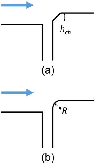
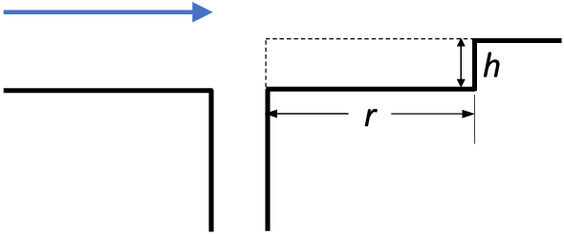
A small set of chamfered and rounded edges was tested by machining the desired shape into the leading edge of the offset or gap filler piece installed at the model joint (Fig. 3); the piece representing the trailing edge of the upstream slab was square and sharp in all cases. Only 45° chamfers and ¼-round radius edges were tested; edges had a 6.35-mm () radius or chamfer. Total offset heights were similar to the dimension of the edge treatments, and gap widths were all of slightly larger dimension (i.e., ).
Tilted Joints
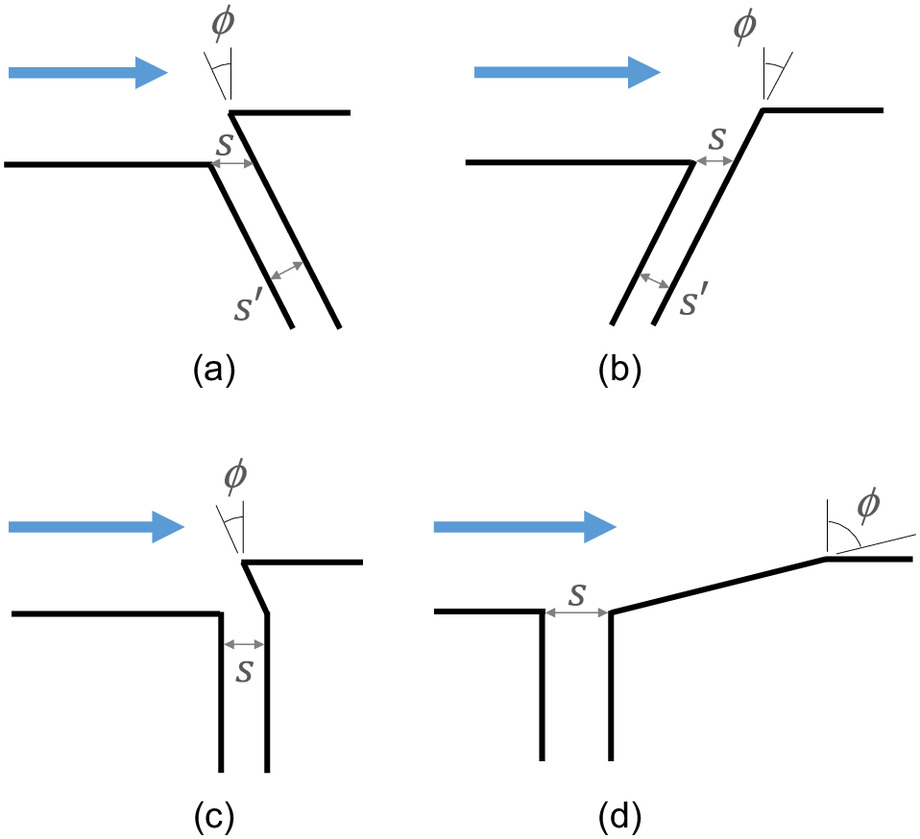
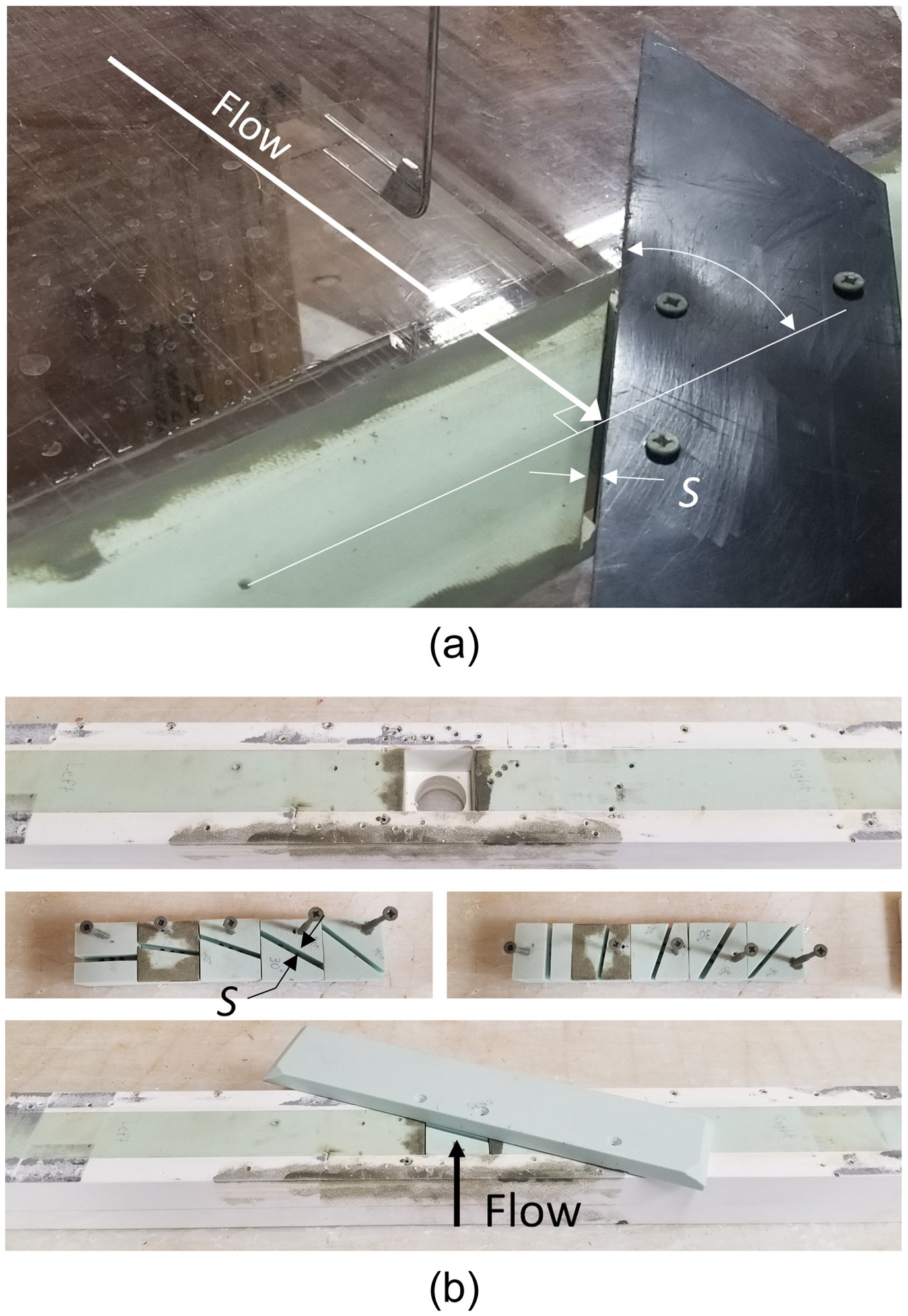
Tilted joints are those in which the axis of the joint is perpendicular to the flow direction, but the upstream face of the offset is rotated around the joint axis to produce a tilt into or away from the flow. A few tests were performed with joints constructed so that the tilt of the offset face also extended below the surface of the chute [Figs. 4(a and b)], but results quickly showed that the geometry of the opening below the chute surface had no effect on uplift pressure as long as the tilt extended at least down to the chute surface. As a result, most of these tests were performed with geometries like those shown in Figs. 4(c and d), with the tilted upstream face connected to a vertical slot passing through the floor of the flume. The gap width for these tests was defined as (Fig. 4), in the plane of the chute surface, although in some cases it was more convenient to measure physically and calculate . In the field it probably would be convenient in most cases to measure directly in the plane of the chute at the chute surface using a rule, scale, or inside calipers. Table S1 provides the test configurations and data, in which values of indicate a tilt away from the flow, and indicates a tilt into the flow.
Tilts away from the flow are significant because they represent beveling that could be performed to reduce uplift pressure at existing offsets. A wide range of tilt angles away from the flow was tested to examine the value of minor beveling (similar to chamfers) versus major beveling similar to treatments that might commonly be applied for cavitation prevention [e.g., Fig. 4(d)]. Joints described here as tilted away from the flow correspond in geologic terms to rock strata dipping against the flow direction. Similarly, joints tilted into or toward the flow correspond to rock strata dipping in the flow direction. The testing considered cases in which downstream strata protruded into the flow, although the ease with which such layers can be stripped away may tend to eliminate such offsets into the flow naturally over time; these spillway surfaces may develop a profile more akin to that of a stepped spillway with skimming flow from tip to tip, unlike the type of flow tested here.
Relieved Joints
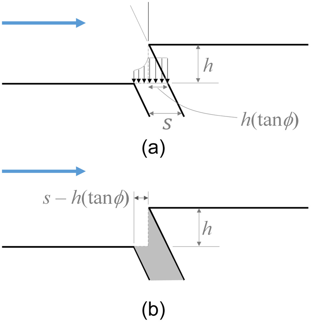
An alternative to beveling existing offsets to reduce uplift pressure is the milling of the offset to create a flush alignment of the slab surfaces at the opening and shift the offset to a location downstream from the open joint (Fig. 5). The distance from the downstream edge of the open joint to the upstream face of the shifted offset is the relief distance, . With increasing , the uplift pressure at the joint is reduced. Tests were performed to determine the reduction ratio compared with the nonrelieved condition.
Skewed Joints
Skewed joints have the axis of the joint rotated in the plane of the chute so that it is not perpendicular to the flow direction. Skewness may occur for exposed rock joints in unlined spillways, or in concrete-lined chutes with horizontal curvature and/or superelevation that causes the convenient layout of joints during construction to not align perfectly with the flow direction. For a joint that is skewed but not tilted, the face of the offset is normal to the plane of the chute surface (i.e., vertical if the chute is horizontal). Two different construction methods were used to create skewed joints for testing. Both performed similarly, and the data are combined in the results. The first construction had a skewed slot constructed at a fixed angle in a foam block that filled the entire chamber in the floor, with an offset installed at the downstream edge of the skewed joint opening [Fig. 6(a)]. This construction allowed measurement of uplift pressure and testing of flow rate through the joint, because the joint had a significant length. The second construction method used a receiving block mounted within the chamber in the chute floor, with the block designed to receive 25-mm (1-in.) square foam inserts with slots machined at various skew angles [Fig. 6(b)]. With the insert in place, an offset piece was installed above the insert and small ports through the insert (with diameter equal to the slot width) allowed uplift pressure to be transmitted to the sealed chamber below. The inserts could be installed and removed quickly to facilitate rapid uplift pressure testing, but the small ports produced flow rates that were too small to be measured accurately with the V-notch weir described previously. For all skewed joints, the gap width, , was defined normal to the joint axis [Fig. 6(a)]. This allowed the relative uplift at a joint with a given gap width to be compared directly with the uplift that would be experienced for the same joint offset and gap in a nonskewed orientation.
Cracked Concrete Specimen
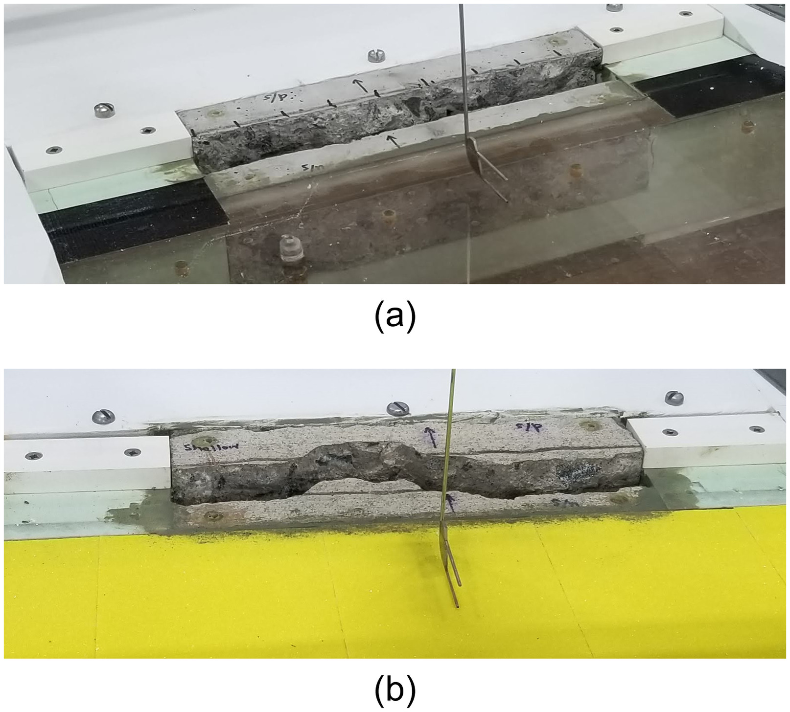
The configurations described thus far address the relatively prismatic geometry of typical spillway joints. To assess the uplift associated with a nonprismatic, midslab crack, a specimen of concrete 238 mm long by 70 mm wide by 63.5 mm thick () was cracked intentionally using a structural testing machine and then cut to size so that it could be mounted within a receiving block that fit into the chamber in the flume floor. The specimen was scored prior to loading to obtain a relatively straight break that would enable it to fit within the 76-mm-wide (3-in.) chamber; the break on one surface was relatively straight, whereas on the opposite surface the break was much more jagged and irregular (Fig. 7). The specimen used a typical concrete mix design with aggregate as large as 19 mm (). The straight break occurred on the smooth side of the specimen, which had a steel trowel surface finish, whereas the opposite side with the jagged break line had a rougher broom finish. The specimen was tested in three orientations. Two 180°-opposite installations with the smooth surface and straight crack exposed to the chute flow were used to test reversed flow directions, and the jagged crack and rough surface were tested in one orientation. For this latter installation, an overlay of 80-grit sandpaper was adhered to the flume floor for a distance of about 1.2 m (4 ft) upstream to produce a boundary layer condition that was more representative of what would occur in a spillway with a broom finish or other roughness, such as weathered concrete. The tests were performed at only one offset height [nominally, ()] and gap width condition [ ()]; a relatively large gap was used to allow a significant offset to be created without interference between the jagged roughness elements within the crack. The offset heights were measured for each test after installation of the cracked specimen into the flume. The gap widths were determined based on dimensions of the specimen and the block into which it was mounted, since they could not be measured accurately after installation due to the jagged nature of the opening.
Test Procedures and Measurements
Detailed test procedures for determining sealed-joint uplift and flow through partially vented joints were described by Wahl and Heiner (2024a, b). The basic procedure was to measure uplift pressure and the chute velocity profile with the joint chamber sealed, and then to measure the joint flow rate and back-pressure below the joint as the joint chamber valves were opened incrementally. The difference between the sealed uplift and the vented backpressure was taken to be the driving head for orifice flow through the joint. Similar procedures were used for testing of the various irregular joint configurations, with one simplification; for those configurations that could be varied readily and rapidly from one orientation or configuration to the next, uplift pressures and joint flow rates were measured repeatedly for the same discharge in the chute without repetition of the velocity profile measurements. For each test series, a small number of tests were performed at other flow rates to verify that normalized results were not sensitive to the specific magnitude of the chute discharge.
Wahl and Heiner (2024b) discussed the detachment of the chute flow from the floor for large offsets, which causes increased uplift pressure. The majority of the irregular joint testing was conducted with flow attached to the chute floor; a few tests of the cracked concrete specimens also were conducted with detached conditions, and the results were consistent with the prior relationships developed for detached flow at regular joints (Wahl and Heiner 2024b).
Analysis and Results
Chamfers and Rounded Edges
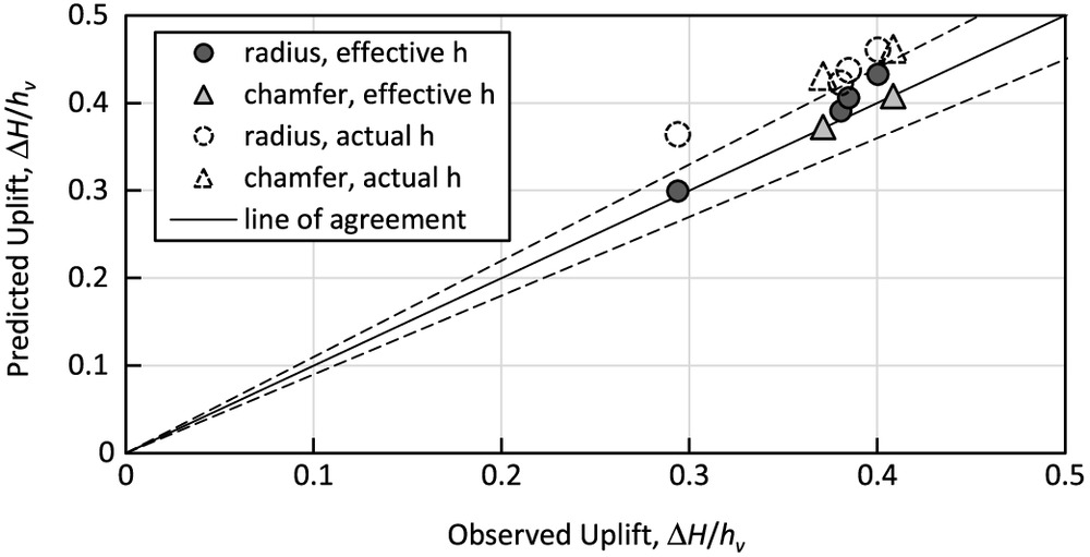
Chamfering and rounding of the leading edge of the offset caused a small reduction of the uplift pressure measured in the sealed joint compared with that for sharp-edged offsets with similar and dimensions. Fig. 8 shows observed uplift pressures and predicted uplift pressures computed with Eqs. (3)–(5) using actual offset heights and adjusted or effective offset heights. For 45° chamfers (the only angle tested), reasonable agreement was obtained by taking the effective offset height to be , where is the chamfer height, which in these tests was 6.35 mm (). This indicates that the effective tip of the offset is at the midpoint of the chamfered edge. For rounded edges with circular arcs, reasonable agreement was achieved when the effective offset height was , which placed the effective tip of the offset at the height of a bisector of the 1/4-round edge. No tests of flow rate through joints were conducted with chamfered or rounded offsets, but the procedures described by Wahl and Heiner (2024a) should be effective using estimates of the driving stagnation pressure obtained for the modified offset heights described here.
Tilted Away, or Beveled
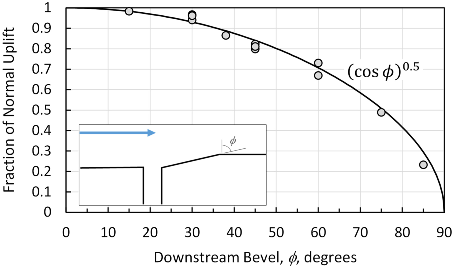
Beveled grinding is a remediation method typically applied to existing offsets into the flow during spillway maintenance work. Tests were performed to determine the reduction of uplift pressure produced by different bevel angles. For each test, the measured uplift was compared with that which would be predicted using Eqs. (3)–(5) assuming a regular geometry with the face of the offset perpendicular to the chute floor. The fractional uplift is given by (Fig. 9), which means that there still is significant uplift (more than 20% of the reference value) until the bevel angle reaches 88°, or 2° above the plane of the chute.
Tilted into Flow
Offsets tilted into the flow overhang at least a portion of the open joint, and initially were observed to produce relatively small uplift pressure increases compared with the reductions found for offsets tilted at similar angles away from the flow. This is believed to be due to the fact that with the chamber below the joint sealed, the water within the joint and under the shelter of the overhang is effectively stagnant, so an offset tilted into the flow behaves much like an equivalent geometry in which the offset is vertical, but the face is located farther upstream [Fig. 10(b)].
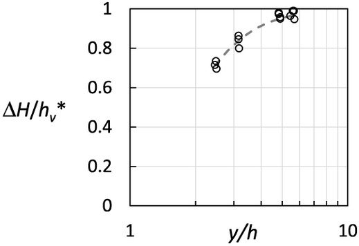
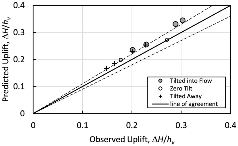
A procedure for predicting the uplift pressure in the joint was developed by estimating the pressure distribution applied to the top of the open joint to be a combination of that due to the equivalent vertical-faced offset and a pressure applied beneath the overhanging tip of the offset. To determine this latter pressure, a series of tests was performed with offsets tilted far enough upstream to completely overhang the joint opening. A relation like those developed by Wahl and Heiner (2024b) for each ratio was determined with the uplift pressure head given bywhich is a special application of Eq. (5) with and determined by a visual fit (Fig. 11). This pressure was applied to the covered portion of the joint opening with width [Fig. 10(a)]. If the tilt completely overhangs the joint, this is the predicted uplift pressure for the entire joint. If the tilt does not completely cover the joint, the average pressure applied to the remaining portion of the joint with length is determined using Eqs. (3)–(5) with . A weighted average of the two pressures based on the length over which they are applied determines the pressure within the joint. The relative increase in uplift due to the tilt into the flow is limited when is small and/or is large, because these cases already have relatively large uplift with little opportunity for increase; when is large and/or is small, the situation is reversed, and tilt into the flow can produce larger relative increases in uplift. This method worked well when applied to limited test data obtained from two joints with and (Fig. 12).
(8)
Relieved Joints
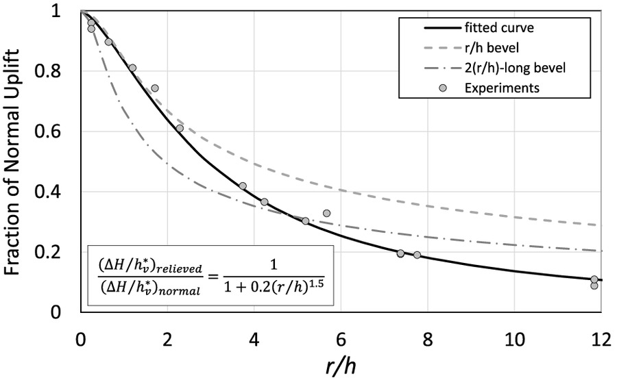
Reducing uplift pressure in a joint by use of a milled relief slot was illustrated in Fig. 5. Tests of a variety of joints modified in this way showed that the relative reduction of uplift pressure as a function of the normalized relief distance, , is . For comparison, Fig. 13 also shows this relation and the relative reduction achieved by a straight bevel of the same length, which removes half the volume of surface material, as well as a bevel with length , which removes the same volume as the milled slot. For the relief slot was more effective than a bevel of the same length, and for the milled slot also outperformed the double-length bevel. A slot with relief distance reduced uplift to 10% of the untreated value, whereas a bevel of 89.4° was needed to achieve a similar reduction. In many cases, especially when access for milling equipment is feasible in the spillway chute, the relief slot may be more economical and more effective than bevel grinding.
Skewed Joints
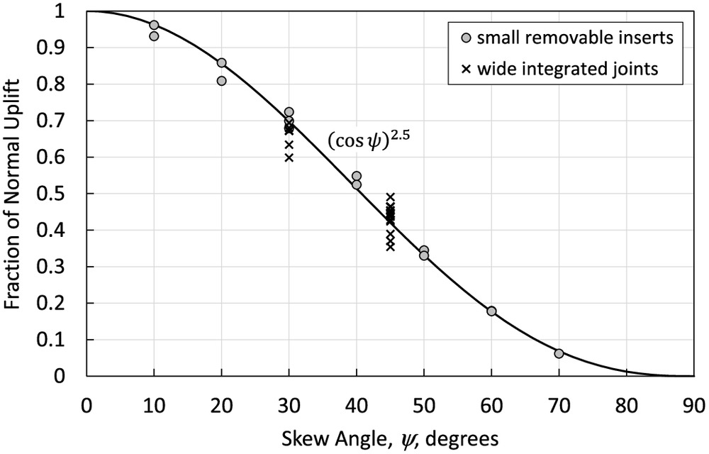
Skewed orientations were tested using the two experimental setups in Fig. 6. The tests were used to determine the fractional uplift relative to a joint with the same gap width oriented perpendicular to the flow. Two wide, integrated joints were tested, one with and the other with . The gap width for each setup was fixed, but each was tested with several offset heights and at several flow rates, with individual chute velocity profiles measured for each test. The removable inserts shown in Fig. 6(b) were tested at several preset flow rates which could be established quickly after each insert was installed; the chute velocity profile for each flow condition was measured only once, when the first insert was tested, and the same offset height was used for all tests. Inserts were not tested at (perpendicular to the flow direction) or at or 90° because the orientation almost parallel to the flow direction caused the end of the insert’s slot to create flow stagnation, so the results did not accurately represent the behavior of a very long slot. The fractional uplift for the skewed joints is well represented by (Fig. 14).
Combined Tilt and Skew
A limited series of tests was performed with combined tilt and skew, using two different ratios. The skewness angle was and tilt angles were , , 0°, , and , where negative values indicate tilt away from the flow and positive values indicate tilt into the flow. The relationships developed from the separate tests of tilted and skewed joints were applied to predict the uplift pressure heads, and the observed uplift pressures tended to be about 12% low for the combined cases (Fig. 15). Apparently, the incomplete stagnation that results from a skewed orientation tends to reduce the pressure increase caused by a tilt into the flow and amplifies the reduction due to a tilt away from the flow.
Cracked Concrete Specimens
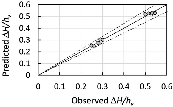
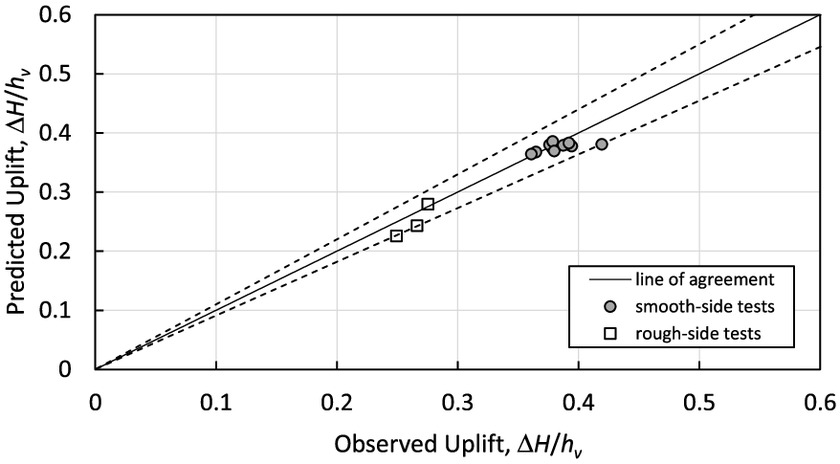
The cracked concrete specimens were tested at seven different flow rates for the first installation in which the smooth surface and straight crack were exposed to the flow, four flow rates for the same crack tested in the reversed flow direction, and three flow rates for the tests of the roughened side of the specimen with the more jagged crack shape. Fig. 16 presents the observed uplift pressures and those predicted using Eqs. (3)–(5). The results agreed within , similar to the uncertainty observed in tests of regular square-edged joints by Wahl and Heiner (2024b). The average error in relation to the mean channel velocity head was , and the RMS variation of the differences was .
Flow into Joints
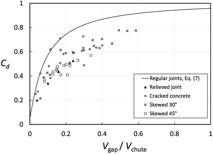
Testing of normally oriented square-edged joints (Wahl and Heiner 2024a) produced Eq. (7) for predicting the discharge coefficient as a function of the velocity ratio, . These discharge coefficients seem to primarily represent an entrance loss, with minimal influence of friction through the joint. Many of the modified joints discussed in this paper (skewed, beveled, relieved) generate less stagnation pressure than normally oriented square-edged joints, and thus also will cause less discharge through the joints even with no change in the discharge coefficient. However, limited testing of some of these modified joints showed that there was a general reduction of the discharge coefficient (with significant scatter) for nonrectangular joints (Fig. 17 and Table S2 ). For skewed orientations this probably is due to incomplete stagnation of the flow. For the joints with relief slots, the lack of an offset exactly at the joint also prevents true flow stagnation over the joint opening. Reduced discharge coefficients for the cracked concrete specimens probably were due to friction loss through the rough flow passage. No attempt was made to develop relations for predicting these reduced discharge coefficients; Eq. (7) will generally yield conservatively large estimates of the flow through a variety of modified joints. Flow testing was not performed for joints tilted into or away from the flow.
Discussion
Prior tests of square-edged joints with regular perpendicular offsets into the flow have shown that large uplift pressures beneath concrete chute linings are possible, as well as large flow rates into joints when waterstops or other joint-filling materials are not present or effective (Wahl and Heiner 2024a, b). To mitigate against possible failure, existing poor joints and other defects should be treated to reduce or eliminate the effects of offsets into the flow. Elimination or reduction of offsets will reduce both uplift pressure and potential inflow through a joint. Several potential modifications were tested. Angled beveling of offsets was not highly effective until bevel angles are extremely flat, but the creation of relief slots holds significant promise for producing more pressure reduction with less volume of material removal for .
For unlined rock chutes, testing of skewed and tilted joints showed that both factors can change uplift pressure significantly; skewness always reduces uplift while tilt has the potential to either increase or decrease uplift. Some of the idealized configurations tested here may be relatively unlikely to occur in a rock-lined channel, except in localized cases, and may be transitory (Fig. 18). In addition, the existence of repeated, multiple offsets into the flow combined with tilts into or away from the flow could create complex flow conditions near the boundary that would differ significantly from the tests of isolated offsets reported here.
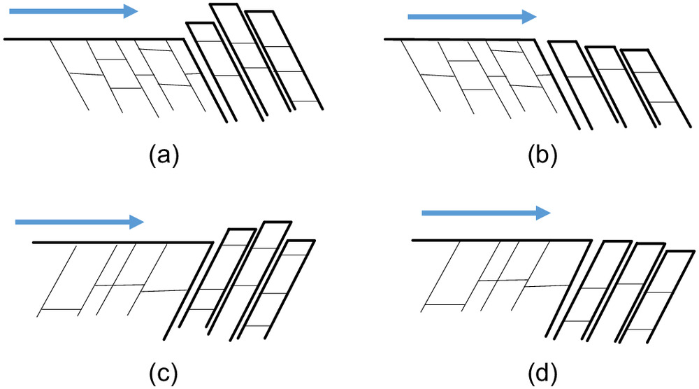
Rock scour prediction methods have long recognized that the orientation of joints relative to flow direction is an important factor in erosion, even if solely due to additional degrees of rock block removal freedom provided by certain orientations. The rock rippability index of Kirsten (1982) and the headcut erodibility index of Annandale (1995) both contain a ground structure number that indicates that the most effective removal of rock occurs when the most closely spaced joint sets in a rock formation dip at about 30°–70° in the flow direction [Figs. 18(a and b)] or direction of ripping (i.e., with joint openings tilted into the flow). In this orientation the flow is effective at entering the joints, which also are oriented to enhance block removal. A second maximum occurs when primary joints dip against the flow or ripping direction by about 30°–60° [Figs. 18(c and d)]; in this orientation, primary joints may be less prone to erosion, but secondary joint sets still can provide freedom of movement that facilitates rock removal, even if pressures within primary joints are reduced by the joint orientation. In addition, the test results for joints tilted away from the flow showed that uplift forces remain relatively high until joints are tilted away from the flow at extreme angles.
Data from separate tests can be viewed as scale models of one another. For example, a ratio of 1.0 can be produced with a 1-mm gap and 1-mm offset, or a 10-mm gap and 10-mm offset, and so forth. Many joints with similar ratios were tested at differing scales. Similarly, tests with fixed joint size and geometry were performed at a wide range of depths, velocities, and discharges. Results from the full velocity and geometric scale range of these tests were represented accurately by the relations presented here, in which uplift pressure is normalized with respect to velocity head of the mean flow and velocity head within the boundary layer. As explained previously, these tests were all conducted in nonaerated flow conditions. Thus, as long as nonaerated flow is maintained, the relations presented here should be applicable to all velocities. Future research to test aerated flow conditions would be valuable, both for spillways that are naturally aerated and for those that are equipped with aerator structures to mitigate against cavitation damage.
For ratios less than about 5, there also should be no limit to the application of these equations to joints of varying scale. For , there is a minor scale effect related to gap size and the nonlinear deterioration of the boundary layer that occurs as the approach flow crosses the open gap upstream from the offset face of the joint. This was discussed in detail by Wahl and Heiner (2024b).
Conclusions
Uplift pressures were measured at a variety of modified joints that may be encountered in spillway chutes, including joints that have chamfered or rounded edges, skewness relative to the flow direction, and tilts into or bevels away from the flow. The latter can be a typical remediation option for spillways with existing offsets into the flow, and this study also considered other geometries for that purpose, such as a novel relief gap that separates the joint opening from the offset itself. The experimental data were used to develop relations for predicting the increase or decrease of uplift pressure associated with modified joints. Testing of cracked concrete specimens showed that uplift pressures can be predicted accurately from the data already collected from normally oriented square-edged joints. Flow rates through most of the modified joints, including the cracked concrete specimens, should be lower than those that would be predicted for normally oriented square-edged joints.
Future spillway construction and repair practices can be informed by the results of this study. In particular, joints skewed 45° from a normal orientation experience less than half of the uplift of typical joints, although this may not be a practical change to incorporate into regular construction. The most effective means for eliminating existing spillway uplift issues is elimination of offsets into the flow. However, traditional beveled grinding of offsets is shown to have limited effectiveness unless bevel angles are extreme, with an 88° bevel needed to achieve 80% reduction of uplift. When the goal is more than 70% uplift reduction, relief slots are more effective than bevels that involve the same volume of material removal.
Notation
The following symbols are used in this paper:
- curve-fitted parameter;
- curve-fitted parameter;
- base of natural logarithms, approximately 2.718;
- Darcy–Weisbach friction factor;
- acceleration due to gravity on Earth, ;
- offset height;
- chamfer height;
- velocity head computed from mean channel velocity, ;
- velocity head of boundary layer flow between chute floor and the tip of offset;
- exponent in velocity profile equation, ;
- discharge per unit width through joint or crack;
- radius of rounded edges;
- relief distance from downstream edge of open joint to face of offset;
- gap width;
- average velocity in spillway chute;
- width of open joint across width of chute, perpendicular to flow direction;
- flow depth;
- energy coefficient relating true velocity head to ;
- energy coefficient relating to ;
- joint gap width to offset height aspect ratio, ;
- uplift pressure head within sealed (nondrained) joint;
- uplift pressure head within simulated joint during joint flow;
- angle of chute slope below horizontal;
- von Kármán ;
- angle of joint rotation from perpendicular to chute surface (tilt); and
- angle of joint rotation from perpendicular to flow direction (skewness).
Supplemental Materials
File (supplemental_materials_jhend8.hyeng-13994_wahl.pdf)
- Download
- 234.60 KB
Data Availability Statement
All data that support the findings of this study are available from the corresponding author upon reasonable request.
Acknowledgments
This work was jointly funded by the Bureau of Reclamation Dam Safety Office (Technology Development Program) and Research Office (Science and Technology Program). Model makers Jimmy Hastings, Jason Black, Jeffrey Falkenstine, and Dane Cheek constructed many of the unique test facility components. Trevor Stockton of the Concrete & Structural Laboratory performed the cracking of the concrete specimen. Joshua Mortensen in the Hydraulics Laboratory provided internal peer review.
References
Annandale, G. W. 1995. “Erodibility.” J. Hydraul. Res. 33 (4): 471–494. https://doi.org/10.1080/00221689509498656.
Bollaert, E. 2010. “The comprehensive scour model: Theory and feedback from practice.” In Proc., 5th Int. Conf. on Scour and Erosion. London: International Society for Soil Mechanics and Geotechnical Engineering.
Bollaert, E. F. R., and A. J. Schleiss. 2005. “Physically based model for evaluation of rock scour due to high-velocity jet impact.” J. Hydraul. Eng. 131 (3): 153–165. https://doi.org/10.1061/(ASCE)0733-9429(2005)131:3(153).
Bureau of Reclamation. 2001. Water measurement manual. 3rd ed. Washington, DC: U.S. Govt. Printing Office.
Chen, C. L. 1991. “Unified theory on power laws for flow resistance.” J. Hydraul. Eng. 117 (3): 371–389. https://doi.org/10.1061/(ASCE)0733-9429(1991)117:3(371).
Frizell, K. W. 2007. Uplift and crack flow resulting from high velocity discharges over open offset joints. Denver: Bureau of Reclamation.
Gardner, M. 2023. “Toward a complete kinematic description of hydraulic plucking of fractured rock.” J. Hydraul. Eng. 149 (7): 04023015. https://doi.org/10.1061/JHEND8.HYENG-13193.
George, M. F. 2015. “3D block erodibility: Dynamics of rock-water interaction in rock scour.” Ph.D. dissertation, Dept. of Civil & Environmental Engineering, Univ. of California.
Ghimire, S. N., and J. W. Schulenberg. 2021. “An automated screening technique to identify at-risk auxiliary spillways: Modified approach in WinDAM.” J. Hydraul. Eng. 147 (8): 06021007. https://doi.org/10.1061/(ASCE)HY.1943-7900.0001889.
Gilbert, D., B. Auld, B. Hall, K. Neff, and A. Rauch. 2023. “Risks for hydraulic jacking in the Chatuge Dam spillway.” In Proc., Annual Conf. Aurora, CO: U.S. Society on Dams.
Hurst, A., M. Foster, and B. Holmes. 2023. “Potential erosion of an unlined rock spillway at New Melones Dam, CA.” In Proc., SEDHYD 2023 Federal Interagency Sedimentation and Hydrologic Modeling Conf. Sandy, UT: SEDHYD.
IFT. 2018. “Independent forensic team report: Oroville dam spillway incident.” Accessed January 9, 2018. https://damsafety.org/sites/default/files/files/Independent%20Forensic%20Team%20Report%20Final%2001-05-18.pdf.
Johnson, P. L. 1976. Research into uplift on steep chute lateral linings. Denver: Bureau of Reclamation.
Kirsten, H. A. D. 1982. “A classification system for excavating in natural materials.” Civ. Eng. Die Siviele Ingenieur in Suid-Afrika 1982 (7): 293–308.
Koulibaly, A. S., A. Saeidi, A. Rouleau, and M. Quirion. 2021. “Identification of hydraulic parameters influencing the hydraulic erodibility of spillway flow channels.” Water 13 (21): 2950. https://doi.org/10.3390/w13212950.
Koulibaly, A. S., A. Saeidi, A. Rouleau, and M. Quirion. 2023. “A reduced-scale physical model of a spillway to evaluate the hydraulic erodibility of a fractured rock mass.” Rock Mech. Rock Eng. 56 (2): 933–951. https://doi.org/10.1007/s00603-022-03101-5.
Nunner, W. 1956. Wärmeübergang und druckabfall in rauhen rohren (Heat transfer and pressure drop in rough pipes). Berlin: Association of German Engineers.
Pells, S. 2016. “Erosion of rock in spillways.” Ph.D. dissertation, School of Civil and Environmental Engineering, Univ. of New South Wales.
Sánchez, P. P. 2022. “Understanding flows over a channel floor with cross-sectional joints.” M.Sc. thesis, Dept. of Building Engineering, Energy Systems and Sustainability Science, Univ. of Gävle.
Smith, P. R., B. Hall, B. Auld, and D. A. Gilbert. 2023. “Practical guidance and experience for interim chute spillway joint repairs.” In Proc., Annual Conf. Aurora, CO: U.S. Society on Dams.
Wahl, T. L., and B. J. Heiner. 2024a. “Discharge through open offset joints and cracks in spillway chutes.” J. Hydraul. Eng. https://doi.org/10.1061/JHEND8.HYENG-13898
Wahl, T. L., and B. J. Heiner. 2024b. “Laboratory measurements of hydraulic jacking uplift pressure at offset joints and cracks.” J. Hydraul. Eng. 150 (4): 04024016. https://doi.org/10.1061/JHEND8.HYENG-13871.
Information & Authors
Information
Published In

Journal of Hydraulic Engineering
Volume 150 • Issue 5 • September 2024
Copyright
This work is made available under the terms of the Creative Commons Attribution 4.0 International license, https://creativecommons.org/licenses/by/4.0/.
History
Received: Nov 12, 2023
Accepted: Mar 25, 2024
Published online: Jul 2, 2024
Published in print: Sep 1, 2024
Discussion open until: Dec 2, 2024
ASCE Technical Topics:
- Bodies of water (by type)
- Channels (waterway)
- Coasts, oceans, ports, and waterways engineering
- Construction engineering
- Construction methods
- Continuum mechanics
- Cracking
- Dynamics (solid mechanics)
- Engineering fundamentals
- Engineering mechanics
- Fracture mechanics
- Geomechanics
- Geotechnical engineering
- Hydraulic engineering
- Hydraulic structures
- Hydraulics
- Jacking
- Mathematics
- River engineering
- Skewness
- Soil dynamics
- Soil mechanics
- Solid mechanics
- Spillways
- Statistics
- Stream channels
- Structural dynamics
- Structural engineering
- Structures (by type)
- Uplifting behavior
- Water and water resources
- Water management
- Waterways
Authors
Metrics & Citations
Metrics
Citations
Download citation
If you have the appropriate software installed, you can download article citation data to the citation manager of your choice. Simply select your manager software from the list below and click Download.